ForewordBridging
rivers , gorges, narrows, straits, and valleys always has played an
important role in the history of human settlement.
Since ancient times , bridges have been the most
visible testimony of the
noble craft of engineers. A
bridge can be defined in many
ways , but Andrea
Palladio , the great
16th century Italian architect and
engineer , hit
on the
essence of bridge
building when he said "...bridges
should befit the
spirit of the community by exhibiting
commodiousness, firmness, and
delight ." In more
practical terms ,
he
went on to explain that the way to
avoid having the bridge carried
away by the
violence of water was to make the bridge
without fixing
any posts in the water. Since the
beginning of time, the
goal of
bridge builders has been to create as
wide a
span as possible which
is commodious,
firm , and
occasionally delightful. Spanning greater
distances is a
distinct measure of
engineering prowess.
In
terms of engineering, bridges are discussed by
design
or type
(
beam ,
arch , truss, cantilever,
suspension , or moveable);
length
(
usually expressed in terms of
clear or
overall span); and
materials
(
stone ,
wood ,
cast and wrought
iron , and what we use
today - concrete
and
steel ). The
purpose of this contextual essay is to
provide parameters of
value and significance so that we can
focus our
attention on those bridges - globally - that
best illustrate the
history of bridge building, and to
encourage their preservation.
What
is a World
Heritage bridge? The World Heritage
Committee states that
to be of World Heritage status a
monument or site must be of
outstanding universal value.
It must illustrate or interpret the heritage of the world in terms of
engineering,
technology , transportation,
communication , industry,
history, or culture. World Heritage
industrial sites and monuments
must meet one or more of the
following criteria and
pass the test of
authenticity:
Represent a
masterpiece of human
creative genius ;
Have
exerted great
influence , over a span of time or
within a cultural
area of the world, on developments in engineering theory, technology,
construction , transportation, and communication;
Be
an outstanding example of a type which illustrates a significant
stage in bridge engineering or
technological developments.
A
World Heritage bridge, like
other properties, must meet the test of
authenticity in design, materials, workmanship, or
setting (the
Committee has stressed that
reconstruction is only acceptable if
carried out on the
basis of complete and detailed documentation of
the
original artefact and to no extent on conjecture). The criteria
of authenticity may
apply to Japanese bridges like the Kintaikyo
spanning the Nishiki
River in Iwakuni or Palladio's bridge over the
River Brenta at Bassano a
Grappa near Venice (
Italy ). In the
same context, some bridges have been moved when unable to
function at
their original
location . It is not
unusual in the USA, for example,
to relocate a
metal truss bridge to a less travelled
road when it can
no longer handle the
traffic ; the same probably holds true for other
countries. This is within the
functional tradition of some bridge
types and should not be viewed as a negative
factor in determining
the
integrity of a relocated structure.
The
definition of authenticity is in the
process of being
expanded to
include intangible
values such as a bridge that embodies the spirit
or character of a people or
place , as New
York City is embodied in
the
Brooklyn Bridge, San
Francisco in the
Golden Gate, London in
Tower Bridge,
Sydney (
Australia ) in the Harbour Bridge, or
Bosnia -Herzegovina in the recently destroyed
Stari Most in Mostar.
Bridges
nominated for World Heritage listing also must have
legal protection and
management mechanisms to ensure their
conservation . The existence
of protective
legislation at the national, provincial, or municipal
level is
therefore essential and must be
clearly stated in the
nomination. Guidelines for nominations state that each property
should be compared with properties of the same type dating from the
same
period ,
both within and
outside the nominating State
Party 's
borders.
For
the purpose of this contextual essay, bridge design and construction
is dealt with chronologically by
material and by type. In
addition to
the obvious evaluation factors as age, rarity, integrity, and the
fame of the
builder , consideration also is given to the substructure
(piers, abutments, foundation), the superstructure (beam, arch,
truss, suspension, and combinations thereof), the materials of
construction (their
strength and properties), the
evolution of
construction techniques, and whether the bridge advanced structural
theory or methods of evaluating material behaviour.
Bridges
discussed in this essay illustrate important types or technological
turning points and are listed at the end. Some, like the
Pont du Gard
(
France ) and the Iron Bridge (UK), are
already inscribed on the World
Heritage List.
Others may be candidates for listing given adequate
study ,
comparison , and evaluation. Not every potential World Heritage
bridge candidate is cited. It is the job of TICCIH and its
member countries to identify and make a case for outstanding bridges so they
can be appreciated and
protected like the great architectural and
natural monuments already designated.
Introduction The
first bridges were natural, such as the huge rock arch that spans the
Ardèche in France, or Natural Bridge in
Virginia (USA). The first
man-made bridges were tree trunks laid
across streams in girder
fashion,
flat stones , such as the clapper bridges of Dartmoor in
Devon (UK), or festoons of vegetation, twisted or braided and hung in
suspension.
These three types - beam, arch, and suspension - have
been
known and
built since ancient times and are the origins from
which engineers and builders derived various combinations such as the
truss, cantilever,
cable -stayed, tied-arch, and moveable spans.
The
essential difference
among types is the way they bear their own
weight - the "dead
load " and the "
live load" - a
person , the railway
train , wind, or snow that is applied to the
bridge. The weight of beam, truss, and girder bridges bears directly
downwards from their ends on the
ground , piers, or abutments. Arch
bridges thrust outwards as well as downwards, acting in compression.
The cables of suspension bridges act in tension, pulling inwards
against their anchorages.
If
two or more beam or girder spans are joined together over piers, they
become
continuous , a form favoured by European engineers, who had the
mathematical
knowledge to
analyse the indeterminate stresses
introduced by such systems. A case in point is the Town lattice truss
invented by Ithiel Town, an American, in 1820, which is a
rare instance of reverse
techno - logical
transfer . The form originated in
the USA, but was widely adopted in
Europe , especially in iron railway
bridges. The lattice fell into disfavour in the USA, where a
preference existed for statically determinate bridges of
heavy timber ,
whose forces were
easier to calculate.
A
more complex form of the beam is the truss, a
rigid self- supporting
system of triangles transferring both dead and live loads to the
abutments or piers. A more complex form of the girder is the
cantilever, where trussed and anchored ends of the girder
support a
central span. They were favoured for
deep gorges or wide
fast -
flowing streams where false
work , a temporary structure, usually of timber,
erected to
assist in the construc- tion of the
permanent bridge, is
impossible to
build . The three principal types - beam, arch, and
suspension - often were combined in a variety of ways to form
composite structures , the type selected depending on the
nature of
the
crossing , the span
required , the materials at
hand , and the type
of load anticipated - pedestrian, vehicular, railroad, or a
channel of water as in aqueducts.
Primitive
bridgesOther
than the clapper bridges of
England and
similar spans surviving in
other countries, bridges dating from prehistoric periods are rare.
Bridges of twisted vines and creepers
found in India,
Africa , and
South America, the ancient cantilevers of
China , Kashmir, and
Japan ,
if any
survive , or the
wooden arches of Japan may be candidates for
World Heritage listing because they perpetuate primitive ingenuity
and craft technology that is important to recognize. Since some of
their materials cannot be original, these structures will have to
pass the test of authenticity.
In
51 BC,
during the Gallic War,
Caesar attested to the construction of
narrow wooden bridges by Gallic builders over wide rivers as the
Loire ,
Seine , and Allier of 600ft (
200m ) span, used by pedestrians
and
domestic animals . The stone vault probably first sprang
forth in
Anatolia and the Aegean region of
Asia Minor (central and
western Turkey ) in the 2nd
millennium BC for short spans in civic
construction. The Mesopotamian civilizations introduced the first
major development of
brick vaulting in the
royal palaces, and also
probably the first important arch bridges in the 6th century BC.
Roman bridges Figure 1 Ponte Saint-Martin (c 25 BC) near
Torino (Italy).
Shunsuke Baba , photographer The
greatest bridge builders of antiquity were the
Romans . They applied a
civil engineering repertoire on an unprecedented
grand scale and
achieved impressive
results . Roman engineering introduced
four significant developments to the art of bridge building that
never had
been
prominent before : the
discovery and extensive use of natural
cement , development of the coffer dam, perfection and widespread
application of the semi-circular masonry arch, and the
concept of
public
works (Figure 1).
In
these important respects, the Roman engineer vastly
improved upon the
efforts of his predecessors. Public water supply was the most
significant aspect of Roman civil engineering:
nothing like it had
been achieved before nor was it to be emulated
until the
19th century. Structural evolution achieved by Roman engineers is manifest
in aqueducts, dam construction, and highway bridges that relied on
the development of concrete, and a
growing awareness of its strength.
The
Romans mixed a cement,
pozzolana,
found
near the Italian town of Pozzuoli (ancient Puteoli), with
lime , sand,
and water to form a
mortar that did not disintegrate when exposed to
water. It was used as a binder in piers and arch spandrels, and
mass-
formed in foundations. Coffer
dams (temporary enclosures built
in river beds to
keep the water out
while the foundations were
established ) were made by
driving timber piles into the river bed,
removing water from the area enclosed, and then excavating the
soft ground inside. Despite the use of coffer dams, Roman bridge
foundations
typically were not deep enough to provide sufficient
protection against scour. Most of the Roman bridges that survive are
those built on
solid rock such as the Pont du Gard aqueduct (
c
AD 14) near Nîmes (France), the
Alcantara Bridge (AD 98) on the
Spanish -Portuguese border, and the aqueduct at Segovia (AD 98), which
are three of the most
famous surviving Roman bridges and aqueducts.
Scholars have researched Roman bridges and aqueducts for many
years ,
so it should be possible to
arrive at a well reasoned
selection of
Roman-built bridges for World Heritage listing.
Bridges
of AsiaFigure 2 Phra Phutthos (12th century), Kompong Kdei vicinity (Cambodia), was constructed at the end of the 12th century during the
reign of Jayavarman VII. With more than
twenty narrow arches spanning 246ft (75m), this is the
longest corbeled stone-arch bridge in the world.
Institute of Asian Culture, Sophia University , Tokyo , JapanBridge
building in Asia extends
back earlier in time than in Europe. Because
structural concepts of suspension, cantilever, and arch were first
developed there with great sophistication, every effort should be
made to identify surviving
examples (Figure 2). China was the
origin of many bridge
forms :
Marco Polo
told of 12,000 bridges built of
wood, stone, and iron near the ancient city of Kin-sai. The first
chain -
link suspension bridge, the Panhogiao or Panho Bridge (
c
206 BC), was built by General Panceng during the Han Dynasty. In
1665, a missionary
named Kircher
described another chain-link
suspension bridge of 200ft (61m) made up of twenty iron links, a
common bridge type built during the
Ming Dynasty that was not adapted
until the 19th century in America and Europe. China's oldest
surviving bridge, and the world's oldest
open -spandrel segmental
arch, is the Zhaozhou Bridge (
c
AD 605), attributed to Li Chun and built south-
west of Beijing in
Hebei Province during the
Song Dynasty. Its
thin , curved stone slabs
were joined with iron dovetails so that the arch
could yield without
collapsing. This technique
allowed the bridge to adjust to the
rise and
fall of abutments bearing on spongy,
plastic soils and the live
loads of traffic.
Following
the decline of the Roman Empire with its many engineer- ing
achievements, beam, arch, suspension, and cantilever bridge building
flourished in China while languishing in Europe for
nearly eight
centuries .
Chinese bridge builders experimented with forms and
materials, perfecting their techniques. Selected examples, found in
the
countryside and
parks , may be candidates for World Heritage
listing.
Other
fine bridges survive in
Iran , such as the Bridge of Khaju at Isfahan
(1667), with eighteen pointed arches, carrying an 85ft (26m) wide
roadway with walled, shaded passageways, flanked by pavilions and
watch
towers . This magnificent bridge, combining
architecture and
engineering in splendid functional
harmony , also served as a dam, and
included a hostelry where travellers found cool
rooms for
rest and
refreshment after hot
desert crossings (Figure 3).
Picturesque
bridges, such as the Kintaikyo at Iwakuni (
1673 ), with its
five wooden arches intricately wedged, slotted, and dovetailed together,
are found in Japan. The superstructure of this bridge has been
rebuilt for centuries (the central three arches every 18- 22 years,
and the side spans every 36 years), maintaining the fine craft
tradition of the bridge keepers for centuries (Figure 4). Shogun's
Bridge (
1638 ), crossing the Daiya-gawa River in the
sacred City of
Nikko , is the oldest known cantilever. The bridge was badly damaged
in the typhoon of
1902 , rebuilt, and exists today bearing
foot traffic. It
consists of hewn stone piers pierced with rectangular
holes that
permit the insertion of tightly
fitting cut-stone struts,
two
anchor spans, timber beams jutting out in cantilever form, and a
suspended span.
Figure 3 Bridge of Khaju (1667), Isfahan (Iran), combining architecture and engineering in splendid harmony, functioned as a bridge, dam, and a
resort for thirsty travellers
coming off the desert.
Shunsuke Baba, photographerFigure 4 Kintaiko (1673), Iwakuni (Japan), with its five wooden arches intricately wedged, slotted, and dovetailed, has been faithfully rebuilt for centuries. Each generation of craftsmen has carefully replicated the joinery techniques and materials of their predecessors.
Shunsuke Baba, photographer Medieval bridgesThe
revival of bridge building in Europe following the fall of the Roman
Empire was marked by the
spread of the pointed arch westward from its
origins in the
Middle East . The pointed arch typically was a
Gothic architectural form important structurally in the development of
palaces,
castles , and especially the cathedrals of western Europe,
but not very important for bridges. Medieval bridges continued such
multi -functional traditions as the Isfahan Bridge in Iran. Chapels,
shops, tollhouses, and towers adorned fortified bridges such the 1355
Pont Valentré at Cahors (France) or the Monnow Bridge (1272, 1296)
at Monmouth,
Wales (UK), which were built with defensive ramparts,
firing slits, and drawspans.
Christian
religious orders formed after the fall of the Roman Empire
greatly assisted travellers by building bridges. In western and central
Europe, religious groups
managed popular financial institutions, with
Papal sanction, both for bridge construction and for hospitals. The
influence of these groups lasted from the end of the 12th to the
early 14th century, and their perseverance ensured the construction
of major bridges over wide rivers as the Rhône and the
Danube .
The
bridge over the Rhône at
Avignon (1187), for example, a wooden
deck on stone piers, was built by such an
order under the inspired
vision of a young shepherd,
later canonized as St Bénézet for his
accomplishment. The four surviving arches, dating from the bridge's
rebuilding
around 1350,
rank as one of the most remarkable monuments
of medieval times in view of the 101-110ft (31-34m) elliptical arches
with radii varying at the
crown and haunches.
As
the Middle
Ages drew to a
close , stone arches of remarkable spans
were built in
mountain valleys where rock abutments
provided solid
foundations for spans in excess of 150ft (50m), such as the
Vieille-Brioude and the
Grand Pont du Doux in France.
Renaissance and Neo- Classical bridgesThe
great era of medieval bridge building was followed by the
Quattrocento ,
the transition period from the medieval period to the Italian
Renaissance, when the
confidence and unbounded enterprise of
engineers was manifested in bridges like the 1345 Ponte Vecchio, an
early Florentine bridge in Italy,
designed by Taddeo Gaddi, that
carries a
street of goldsmiths' shops on three segmental arches. This
was followed by the technical efficiency and
artistic advancement of
Renaissance ideals of civic order during the Neo-Classical period of
the
17th and
18th centuries, represented by long span and multiple
stone arches: eg
Santa Trinità (1569) in
Florence , the Rialto (1591)
in Venice, and the Pont Neuf (1607) in
Paris . These bridges, which
are among the most famous bridges in the world today, are all on the
World Heritage List,
although only as components of
historic town
centre inscriptions. Renaissance engineers had learned much about
foundations since Roman times, though they rarely were able to
excavate deeply enough to
reach hard strata. They had,
however ,
perfected techniques of spread footings - wide timber grillages
resting on piles driven into the river bed upon which stone piers
were laid. In the foundation of the Rialto Bridge, designer Antonio
da Ponte drove six
thousand timber piles, capped by three stepped
grillages so that the
abutment stones could be laid perpendicular to
the thrust lines of the arch. Though built on soft alluvial soils,
the bridge continues to support a street of jewellery shops enjoyed
by tourists four centuries later.
The
end of the Italian Renaissance witnessed a new vision of bridge
construction. More than merely utilitarian, bridges were designed as
elegant, grand
passage -ways that were
part of the
visual perspective
of the idealized cityscape - major accents to the totally redesigned
merchant and capital cities. No
country attempted to advance this
concept more than France at the end of the 16th century, where a
national transportation
department of
architects and engineers was
set up,
responsible for designing bridges and roads (
Ponts et Chaussées).
This
corps of specialists
gave the Neo-Classical period a range of
monumental and elegant bridges on rivers as the Loire (Blois,
Orléans, Saumur) and the Seine in Paris. This model spread all over
Europe, producing large monumental urban bridges in capitals such as
London, Saint Petersburg, and
Prague .
In
Italy,
Bartolomeo Ammannati evolved a new form for the Santa Trinità
Bridge - a peculiar
double -curved arch whose departure from an
ellipse was deliberately concealed by a decorative escutcheon at the
crown. Its 1:7 rise-to-span
ratio resulted in an elegantly shallow,
long-arch span widely adapted in other bridges of the Renaissance.
The bridge was reconstructed using original stones recovered from the
river following demolition during World War II.
By
the mid-18th century, masonry bridge building had reached its apogee.
French engineer Jean-Rodolphe Perronet designed and built the Pont de
Neuilly (
1774 ), the Pont de Saint-Maxence (1785), and the Pont de la
Concorde (1791), the
latter completed when Perronet was eighty-three.
Perronet's design
goals were to
slim down the piers and to stretch
arches to the
maximum . The Pont de la Concorde
still represents the
perfection of masonry arch construction,
even though sceptical
officials forced Perronet to shorten the unprecedented centre span of
the bridge to 92ft (28m). Long, elegant, elliptical arches, piers
half their
former widths, special machinery for construction, and the
introduction of an architectural motif used until the
1930s , the open
parapet with turned balusters, completed this outstanding bridge.
Widened in the 1950s, its original appearance was carefully
maintained. Another masterpiece of the French Classical style is the
Pont de Bordeaux of nineteen arches, more than 1640ft (500m),
completed in 1822.
Figure 5 Pontypridd Bridge (1756) over the Taff in South Wales (UK), had to be rebuilt
several times until its builder, William Edwards, got the
correct rise-to-span ratio to ensure that the 140ft (43m) arch would not collapse after removal of the falsework.
Shunsuke Baba, photographerIn the
United Kingdom, a young
Swiss engineer, Charles Labelye, was building
the
English equivalent of Perronet's bridges. On his first bridge,
Westminster (1750) over the
Thames , he developed the caisson, which
made it possible for
pier foundations to be built in deep,
fast-flowing
waters . To solve a problem that had
confounded bridge
builders since Roman times, Labelye used huge timber boxes
constructed on
shore , floated into
position , and slowly sunk to the
bottom of the river by the weight of the masonry piers being laid
above . Fifteen semicircular arches, incrementally diminishing in
length from the centre and rising in a graceful camber, set a high
engineering and architectural standard that stood for over a
hundred years.
England's
other great bridge designer during this period, John
Rennie , built
the first Waterloo Bridge in 1811. Its level road and arches lasted
until 1938. Rennie's next great bridge was
Southwark Bridge (1819),
also over the Thames in London, which was built not in stone but in
the new
miracle material of the 19th century - cast iron. It had
three arches whose central span of 240ft (73m) dramatically
demonstrated the potential of the new material.
Wooden
bridgesWooden
bridges are some of the most ancient. The first Roman bridge, the
Pons Sublicius (
c
621 BC), was a wood-
pile structure over the
Tiber in Rome, extending
pedestrian
access to the Aventine Hill. The earliest detailed
description of a wooden bridge, a timber-pile structure over the
Rhine constructed in 55 BC, was written by Julius Caesar in his
De Bello Gallico.
The best extant model of this type survives today over the Brenta at
Bassano a Grappa, near Venice. It was built by Palladio in 1561,
destroyed in 1945, and reconstructed identical to the original in
1948.
By
the mid-18th century, carpenters
working in the forested regions of
the world
further developed the timber truss bridge. The most famous
were two Swiss
brothers , Johannes and
Ulrich Grubenmann, who built
bridges at Schaffhausen, Reichenau, and Wettingen that combined
diagonal struts and trusses to produce remarkably long spans for
their time. The Schaffhausen Bridge (1757), over the Rhine in
northern Switzerland, had two spans, 171ft and 193ft (52m and 59m)
respectively, which rested lightly on an
intermediate pier when
loaded. It was burned by the French in 1799 during the Napoleonic
Wars. One of the few Grubenmann bridges to survive is Rumlangbrücke
(
1766 ), with a span of 89ft (27m).
Figure 6 Bridgeport Bridge (
1862 ), clear-spanning 208ft (63m) over the South Fork of the
Yuba River near Grass
Valley ,
California (USA), has two
parallel trusses
based on the Howe patent of timber and iron rods, flanked by solid wooden arches cut to the curves and
reflected in the exterior siding. It is the second longest covered wooden bridge span in the USA, after the Blenheim Bridge (1855) in New York State, which is 210ft (64m).
Jet Lowe , HAER Collection European
engineers visiting the New World during the 19th century marvelled at
the spans achieved by American timber bridges. Especially noteworthy
was Louis Wernwag's 340ft (104m) arch truss of
1812 , the "
Colossus ,"
over the Schuylkill in Philadelphia, the longest spanning bridge in
the world at the time. Covered bridges, sheathed in wood to keep the
structural timbers from deteriorating, are an
icon of the American
landscape . Outstanding spans that survive today include the
Cornish-Windsor Bridge (1866) over the Connecticut River and the
Bridgeport Bridge (1862), whose clear span of 208ft (63m)
makes this
gateway to the California goldfields the second longest
single span.
According to the National Society for the Preservation of Covered
Bridges Inc, some 800 wooden covered bridges survive in the USA, more
than in any other country (Figure 6).
Regardless
of the capability of advanced societies like the Romans to build
bridges in stone, the material for the ages, its
cost always remained
a problem. Wooden bridges were an economic
alternative important to
every civilization during all historic periods from prehistoric times
to the first American settlement, from classical Rome to the European
Enlightenment,
including China, Japan, and south-east Asia. Wooden
bridges have played a major role in the history of human development.
The architectural varieties and structural types - girder, arch,
suspension, truss, pontoon, and covered - were numerous. By virtue of
the nature of their material, extant examples are scarce, as is the
historic
record . Nature, acts of God, war, and
arson have decimated
wooden bridges
throughout time. A special
global effort should be
initiated to identify, access, and
protect wooden structures of all
kinds. A group of experts should be convened in the USA and in other
parts of the world where timber bridges survive to recommend a
selection for nomination to the World Heritage List.
Theoretical
advances during the Renaissance and Neo-Classical periodThanks to Galileo, Renaissance mathematicians and scientists understood beam
action and the theory of framed structures. The truss, used by the
Romans as stiffening on the Rhine bridge (55 BC) and in
roof structures, was refined by the Italian architect- engineer Andrea
Palladio. His
classic treatise on
Greek and Roman architecture,
I Quattro Libri dell 'Architettura,
was published in
1570 , and was widely distributed after translation
into English by
Isaac Ware in
1755 . It contained the first drawings
of a truss, the simplest and most easily visualized form for
transferring both dead and live loads to piers and abutments,
accomplished by a rigid self-supporting system of triangles. Palladio
built several truss bridges, the most important being the Bassano
Bridge (1561) over the River Brenta in the
Veneto region in northern
Italy. Destroyed several times, it has been carefully rebuilt
faithfully following the original layout and exists today as the only
example of one of Palladio's bridges.
The
truss form, derived from the Romans, represents one of the
Renaissance's most significant contributions to bridge building.
Renaissance engineers also devised daring innovation in arch forms -
the segmental, elliptical, and multi-centred.
The
Hungarian , Janos Veranscics, reviewed these and other achievements in
the structural arts at the end of the Renaissance in
Machinae
Novae,
published in 1617. Several concepts that later
became standard bridge
practice first were illustrated in this volume: the tied arch, the
Pauli or lenticular truss (in wood), the all-metal truss (in cast
brass), a
portable , metal chain-link suspension bridge, the use of
metal in reinforcing wooden bridges, and the eye-bar tension member
(
again in brass).
In
1716, Henri Gautier published
Traité
des Ponts,
the first treatise devoted entirely to bridge building, during the
Age of
Reason when empirical bridge design gave way to rationalism
and
scientific analysis . The book became a standard work of
reference throughout the 18th century. It covered both timber and masonry
bridges, their foundations, piers, and centring.
A
far-sighted policy that led to the first national department of
transportation in France was
started by Henri IV and Sully at the end
of the 16th century. During the second half of the 17th century, it
was reorganized by Colbert as the Corps des Ingénieurs des Ponts et
Chaussées, a group of state architects and engineers, during the
reign of Louis XIV. In 1747, the École des Ponts et Chaussées, the
oldest academic institution in the world for civil engineering
education in the design of roads and bridges, was started, with
Perronet as its first director. The first theoretical
studies concerning the stability of arches, transmission of forces, and the
multi-radius form were conducted at the school by La Hire, Gautier,
Bélidor,
Coulomb , and Méry.
Iron
bridgesThough
extremely
versatile , wood has one obvious disadvantage - it
burns .
Wernwag's Colossus, destroyed by
fire in 1838, is but one example of
many outstanding wooden bridges
lost in this manner throughout
history. There was another material, however, whose use at the end of
the 18th century offered bridge engineers an alternative to the
traditional materials of timber, stone, and brick. Although it had
first been used in antiquity, iron was the miracle material of the
Industrial Revolution. The Greeks and Romans had used it to reinforce
stone pediments and columns in their
temples and iron links had been
forged by the Chinese and used in suspension bridges.
The
successful smelting of iron with coke,
rather than
charcoal , by
English ironmaster
Abraham Darby in 1709 freed iron
production from
fuel shortage restrictions, made large castings possible, and
facilitated
creation of the arch ribs for the world's first iron
bridge, built seventy years later. In
1754 ,
Henry Cort of Southampton
(England) built the first rolling mill,
making possible the efficient
shaping of bar iron; in 1784 he patented a puddling furnace by means
of which the
carbon content in cast iron could be reduced to produce
malleable iron. These two milestones of metallurgy realized the
potential of iron as a major building material. Bridges were one of
the first structural uses of iron, preceded only by columns (not yet
beams) to support the
floors of textile
mills .
Figure 7 Dunlaps Creek Bridge (1839), Brownsville, Pennsylvania (USA), spans 80ft (24m) on five elliptical ribs of cast iron made of
nine 14ft (4m) segments flanged at the ends and bolted. The triangular bracing in the spandrels is reminiscent of Telford's iron bridges in Shropshire (UK), and the tubes resemble the eliptical arches of the Pont du Carrousel, built over the Seine in Paris in 1834.
Library of Congress The first
successful all-iron bridge in the world was designed by
Thomas Farnolls Pritchard, an architect who suggested using the material as
early as 1773. Built by two ironmasters, Abraham Darby and John
Wilkinson, to demonstrate the versatility of cast iron, the bridge
spans 100ft (30m) over the River Severn at Coalbrookdale (UK), on
five semi-circular ribs of cast iron. The Iron Bridge was followed by
a succession of cast-iron arches built throughout Europe. Few
cast-iron arch bridges were built in the USA as the iron truss,
derived from wooden forms, was
preferred . One iron arch, however,
merits
mention , as it is the oldest iron bridge in America. Dunlaps
Creek Bridge (1839), designed by Captain
Richard Delafield of the
Army Corps of Engineers for the National Road in Brownsville,
Pennsylvania, survives to this day, still carrying traffic (Figure
7). Because the material could be moulded into elaborate shapes,
extravagantly decorative iron arches were used for pedestrian bridges
on the
grounds of estates and
imperial palaces, such as Catherine the
Great's Tsarskoye
Selo in St Petersburg (
Russia ), or urban
pleasure grounds, such as Central Park in New York City (USA). Both places
have remarkable collections of cast-iron arch bridges.
Figure 8 Royal
Albert Bridge, Saltash, Cornwall (UK), was the last great enterprise of Isambard Kingdom Brunel, England's foremost Victorian engineer. This
photograph served as the frontispiece to William Humber's
A Complete Treatise on Cast and Wrought Iron Bridge Construction, published in 1864, and
shows one of the great lenticular spans being jacked into place. It was 445ft (135m) long, consisting of a single wrought-iron elliptical
tube upper chord and a curved bottom chord of linked eyebar chains connected by open truss bracing. The trusses were fabricated on shore, then floated into position and jacked into position over the
Tamar .
Institution of Civil Engineers, LondonEngineers
in the 19th century improved the technology of sinking foundations to
bedrock. Up until that time, coffer dams and
crude caissons were the
only means by which foundations could be constructed in water. Their
use was limited by the length of wooden piles and by soils that were
unsuitable for pile driving because they were either too soft or too
hard. Credit for
developing the first pneumatic caisson belongs to
William Cubitt and John Wright, who used the technique on the bridge
(1851) over the River Medway at
Rochester (UK). It was similar to the
caisson developed by Labelye, but differed in that the
chamber resting on the river's bottom was airtight and required workmen to
enter by means of airlocks after the water had been driven out by
pneumatic
pressure . Working in this environment, men suffered from
the
little understood "caissons disease," now better known
as "the bends." The eventual diagnosis of this condition
permitted the construction of bridges of unprecedented scale,
overcoming the impediment of deep,
broad rivers. Isambard Kingdom
Brunel used the technique for sinking the piers of his bridge at
Chepstow, Wales (UK) and, on a much grander scale, on the Royal
Albert Bridge (
1859 ) over the Tamar at Saltash in Cornwall (Figure
8).
Here , the central pier was built on a wrought-iron caisson 37ft
(11m) in
diameter , sunk to bedrock in 70ft (21m) of water and 16ft
(5m) of mud.
Another
improvement in foundations in the early 19th century involved
hydraulic cement. A better scientific
understanding of the material
by the Frenchman Vicat and the Englishman Aspdin and discovery of the
material in a natural state in 1796 on the
Isle of Sheppey in the
Thames estuary, by Lafarge at Le Teil (France), and by Canvass White
on the Erie
Canal in New York in 1818, led to its use in sinking
foundations by the new
method of direct flow into coffer dams
underwater, as at the suspension bridge at Tournon (France) in 1824.
Hydraulic cement had the
amazing ability to set under water, and was
consequently used in aqueducts, piers and abutments, culverts, and
locks.
Following
the construction of the Iron Bridge at Coalbrookdale, Thomas Telford,
a gifted, self-educated
Scottish engineer, built a number of
cast-iron arches throughout the
British Isles. These included canal
aqueducts, which were extraordinarily innovative
arrangements in
which the cast iron had
real structural value. On both the
Longdon-on-Tern (1796) and the Pontcysyllte (1805) aqueducts, the
cast-iron sections that formed the side walls of the trunk were
wedge-shaped, behaving like the voussoirs of a stone-arch bridge and
bolted
through flanges. Telford's most ambitious
notion , however, was
his
proposal of 1800 for a single cast-iron arch of 600ft (183m) span
over the Thames to replace Old London Bridge. An earlier proposal was
unveiled in France by Montpetit in 1779 for a bridge of 400ft (122m)
over the Seine,
thought to have been the inspiration for Telford's
idea . Even the young United States got into the act when Thomas
Paine , the
political philosopher, proposed an iron arch of 400ft span
over the Schuylkill in Philadelphia. But the next most outstanding
achievement after Coalbrookdale was the cast-iron arch over the River
Wear at Sunderland (UK), because it actually was built. Completed in
1796 by Thomas
Wilson , the bridge had an unprecedented span of 236ft
(75m).
Figure 9 Rio Cobre Bridge (1800), Spanish Town, Jamaica, the oldest iron bridge in the western hemisphere, was designed by Thomas Wilson and employs the same iron voussoir, incremental circular spandrel bracing, and cast-iron plate deck as the earlier Wearmouth Bridge. Essentially a "kit bridge," the system of small castings
held together by wrought-iron ties, tubes, and bolts lent itself to export. Many bridges of this type were shipped to distant
colonies of the British Empire
Eric DeLony, photographerToday,
several collections of cast-iron arches survive in
different countries, the largest being in the United Kingdom, six in the USA, a
few in France and
Spain , and a remarkable selection surviving in
Russia, dating back to the reign of Catherine the Great. These need
to be studied and a selection made for nomination.
By
1800, most European engineers were open to using cast iron.
Architects, however, preferred traditional materials such as
granite and marble for the visible parts of buildings and wood for
hidden structural parts like roof trusses, and did not
accept cast iron as
having aesthetic merit or structural value. In the USA, still blessed
with abundant
virgin forests, the early 19th century was the era of
"
carpenter engineers." Men like Timothy
Palmer , Lewis
Wernwag, Theodore
Burr , and Ithiel Town followed British
custom by
conceiving and building truss forms predicated on intuition and
pragmatic rules of thumb. Their craft tradition of knowledge,
passed down from master to apprentice, contrasted with the scientific
analysis and mathematical formulas practised by French
government engineers. Models were built and loaded to
failure and
broken members replaced with stronger
ones until the model supported loadings
equivalent to a real live load plus a
safety factor.
Patents
were
granted in the USA for composite wood and iron bridges,
transitional structures that capitalized on the availability of cheap
timber. When the American iron industry caught up with Europe's by
the mid-19th century, bridge building
took the direction of composite
pin-connected trusses, with sophisticated castings for
joint blocks
and compression members, and forged eyebars and wrought-iron rods for
tension members, all fabricated to high tolerances. This allowed
them to be
assembled easily and inexpensively in the
field by unskilled
labour using
simple tools and erection techniques. The system
prevailed in the USA because that country lacked a skilled labour
force , and the remoteness of many bridge sites hampered the use of
sophisticated machinery or the shipping of large bridge parts over
long distances. A spirited debate ensued
between England and the
former colony during the last quarter of the 19th century over which
system was best: easily erected pin-connected trusses on the
"American plan," or European-style riveted trusses. Even
though the rigid riveted truss was of
superior design, American
bridges remained competitive in world bridge
markets until the early
20th century because they were
cheaper and swiftly erected.
Figure 10 Gauntless Viaduct (1825) is the only fragment of the original Stockton & Darlington Railway. Fortunately, the ironwork was preserved and featured during the centenary
celebration of the world's first railway in 1825. It was later displayed at the former
rail museum at York, as shown in this photograph. In 1975, when the museum became the new National Railway Museum, it was moved and erected at its original site in West Auckland (UK).
Robert Vogel, Smithsonian Institution, photographerFor years,
the distinction of being the world's oldest surviving iron railway
bridge has been accorded by scholars to the Gaunless Viaduct (1825),
on display at the National Railway Museum, York (UK) (Figure 10).
Designed by George
Stephenson for the first railway, the 37
miles (23km) between Stockton and Darlington in
north -east England, it
consists of four 12.5ft (4m) lenticular truss spans with curved top
and bottom chord members of 2.5in (6cm) diameter wrought-iron rods
and five
vertical iron posts cast integrally with the wrought-iron
chord members. In the last 20 years an older bridge has been
discovered in South Wales (UK) at Merthyr Tydfil, a major early 19th
century iron-producing centre. Pont-y-Cafnau (Bridge of Troughs) is a
unique cast-iron combined aqueduct tramroad bridge
below the
confluence of the Taff and Taff Fechan, built in January-
June 1793 by
Watkin George,
Chief Engineer of the Cyfarthfa Ironworks, to
carry an
edge railway and water channel. An iron trough-like girder is carried
in an A-frame truss of cast iron spanning 47ft (14.2m), held together
by mortise-and-tenon and dovetail joints. The next extant iron
railway bridge
seems to be another recently discovered at Aberdare
(1811), followed by Gaunless. The oldest still in
service is Hall's
Station Bridge, a Howe truss designed in 1846 by Richard Osborne, a
London-born Irishman who worked as engineer for the Philadelphia &
Reading Railroad, although its
current use is vehicular and not rail.
The first major iron truss with pin connections was built in the USA
in 1859, and the earliest iron cantilever in
Germany in 1867, over
the Main at Hassfurt.
Figure 11 Bollman Bridge (
c 1869),
Savage , Maryland (USA). This pre-restoration photograph shows the
paired stanchions
located at mid-span that support the anchorage block where the radiating suspension stays all meet in pinned
connection . The octagonal
profile of the vertical and horizontal compression members was a design motif of Wendel Bollman, the bridge's designer. He,
along with Albert
Fink , who designed a similar type of structure known as the Fink truss,
motivated the chief engineer of the
Baltimore &
Ohio Railroad, Benjamin Henry Latrobe III, to use iron bridges
exclusively for the system's major spans.
William Barrett, HAER CollectionAnother
important composite iron truss surviving from the early period of
iron bridge construction is the Bollman bridge (
c
1869) at Savage, Maryland (USA) (Figure 11).
Britannia
Bridge (1850) across the Menai Straits, Wales (UK), designed by
Robert Stephenson and William Fairbairn, was the prototype of the
plate-girder bridge, eventually used throughout the world. Originally
intended to be a stiffened suspension bridge of four spans, each span
(459ft (140m) over the channel; 230ft (70m)
land spans) consisted of
paired rectangular wrought- iron tubes through which the
trains passed. Although
Navier published his theory of elasticity in
1826 ,
so little was known of structural theory that Stephenson relied
primarily on empirical methods of
testing , modifying, and retesting a
series of models to design the tubes. They were fabricated on site,
floated into position, and raised into place by hydraulic jacks.
Riveting was
done both by hand and using pneumatic riveting
machines invented by Fairbairn. So
strong were the tubes that the suspension
chains were abandoned. The bridge continued in service until
irreparably damaged by fire in May 1970, when the world lost one of
its most remarkable 19th century engineering monuments was lost, but
the near-contemporary Conway Castle Bridge (1848) survives.
Although
the 19th century was marked by significant technological progress,
such breathtaking achievement had its
price . Three- quarters of the
way through the century, two
events , one on either side of the
Atlantic , sobered the engineering profession. These took the form of
accidents: the Ashtabula, Ohio, bridge
disaster of 1876 in the USA,
and the Tay Bridge disaster in
Scotland (UK) in 1879. Forewarnings
had occurred in Europe as early as 1847, when one of Robert
Stephenson's composite cast and wrought-iron girder bridges over the
River Dee on the Chester & Holyhead Railway collapsed. Three
years later, 478 French soldiers were pitched into the Maine at
Angers when one of the anchoring cables of a suspension bridge
embedded in concrete tore loose during a storm, mainly owing to
resonance oscillation and by the oxidation of the iron
wires . The Dee
Bridge disaster spurred the development of malleable wrought-iron
girders, thought to be of safer construction. Collapse of the
Basse-Chaine Bridge resulted in a twenty-
year moratorium on
cable-suspension bridge construction in continental Europe.
Scientific
analysis of bridge design during the 19th centuryIt
took the worst bridge disasters of the century in the USA, Great
Britain , and France to usher in the development of standards,
specifications, and enough regulation to protect the
travelling public. The loss of 83 lives caused by the collapse of a cast- and
wrought-iron truss in Ashtabula prompted an investigation by the
American Society of Civil Engineers. The loss of 80 lives by failure
of a section of the two-mile-long Tay Bridge resulted in similar
inquiries in Britain.
The
reasons for these major failures were similar: ignorance of
metallurgy resulted in uneven
manufacturing methods and defective
castings, and inadequate inspection and
maintenance were
inherent at
both bridges. For the Tay Bridge, exceptionally strong vibrations due
to
dynamic wind stresses under a
moving load created a lack of
aerostatic stability and eventual failure. It took engineers another
quarter-century to perfect bridge design according to advanced
theories of stress analysis, understanding of material properties,
and renewed respect for the forces of nature. A definitive
understanding of the
physical oscillations and vibrations of
structures did not
occur until the middle of the 20th century after
the Tacoma Bridge collapse in the USA in1940.
Advances
in design theory,
graphic statics, and a knowledge of the strength of
materials by engineers such as Karl Culmann and Squire Whipple were
achieved in the second half of the 19th century, but the factor that
most influenced the scientific design of bridges was the railroads.
Engineers had to
know the precise amount of stresses in bridge
members to accommodate the thundering impact of locomotives. Founded
on the pioneering work of the American Squire Whipple and other
European engineers as Collignon, the last quarter of the 19th century
witnessed broad application of both analytical and graphical
analysis, testing of
full -
size members, comprehensive stress tables,
standardized structural sections, metallurgical analysis,
precision manufacturing and fabrication in bridge shops, publication of
industry-wide standards, plans, and specifications, inspections, and
systematic cooperation between engineers, contractors, manufacturers,
and
workers . The combined experience of the railroads, bridge
manufacturing companies, and the engineering communities enabled the
railroads successfully to tackle long-span iron and steel bridges and
long-span trussed-roof train sheds, two engineering icons of the 19th
century.
Figure 12 Whipple Truss Bridge (1867), Normanskill
Farm , Albany, New York (USA), remains in service to this day, restricting only
buses and trucks, thus testifying to the efficacy of Whipple's design. All members are original, their sizes
determined by the forces they carried, deduced from scientific analysis.
Smithsonian InstitutionThe first
practical design
solution was obtained independently in the USA by
Squire Whipple in 1847, and in Russia by D I Jourawski in 1850.
Whipple had been working on the problem since before
1841 , when he
patented and built his all-iron bowstring truss bridge, which proved
exceptionally suitable for short highway and canal spans. His book on
stress analysis,
A
Work on Bridge Building, is
recognized as the USA's
contribution to structural mechanics for the
period. His major breakthrough was the realization that truss members
could be analysed as a system of forces in equilibrium, assuming that
a joint is a frictionless pin. Forces are broken down into horizontal
and vertical components whose sums are in equilibrium. Known as the
"method of joints," it permits the determination of
stresses in all members of a truss if two forces are known. Whipple
clearly outlined methods, both analytical and graphical, for solving
determinate trusses considering uniformly distributed dead loads and
moving live loads. Over a dozen of Whipple's bowstring trusses
survive as elegant illustrations of his breakthrough conclusions
(Figure 12).
The
next advance was the "method of sections" published in 1862
by A
Ritter , a German engineer. Ritter simplified the calculations of
forces by developing very simple formulae for determining the forces
in the members intersected by a
cross -section. The third advance was
a better method of graphical analysis, developed independently by
James Clerk Maxwell,
Professor of Natural Philosophy at
King 's
College,
Cambridge (UK), published in 1864, and Karl Culmann,
Professor at the newly established Federal Institute of Technology
(Eidgenossische Technische Hochschule) in Zürich (Switzerland), who
published his methods in 1866. The solution of bending in a
cantilever was developed over a long period of time, starting with
Galileo's famous illustration of the wooden beam, anchored in the
ruinous masonry
wall , holding a stone weight at its end. Although it
was not entirely accurate, subsequent solutions were discussed in
terms of Galileo's cantilever. C A Coulomb in France hypothesized in
1776 that the flexural stress in a cantilevered beam had a maximum
value in compression on the bottom edge and a maximum value in
tension on the top with a neutral
axis somewhere between the two
surfaces. The problem of understanding bending
moments in
mechanical terms was described by Louis Marie Henri Navier in his
Résumé
de leçons données à l'École des Ponts et Chaussées in
1826. The Swiss mathematician
Leonard Euler provided the solution to
the elastic buckling of columns as early as 1759.
Railroad
viaducts and trestlesRailroads,
the transportation mode that revolutionized the 19th century,
generated a bridge type that merits special attention. The limited
traction of locomotives forced the railroad engineer to design the
line with
easy gradients. Viaducts and trestles were the engineering
solution for maintaining a nearly
straight and horizontal line where
the depth and
width of the valley or
gorge rendered embankments
impracticable. These
massive , elevated structures were first built in
Roman style of multiple-stone arches and piers. Later, when wrought
iron and steel became
available , engineers built viaducts and
trestles of great length and
height on a series of truss spans or
girders borne by
individual framed towers composed of two or more
bents braced together.
Figure 13 Thomas Viaduct (1835),
Relay , Maryland (USA). This illustration from
The United States Illustrated, published in the 1850s, shows the heroic proportions of this massive stone structure, constructed while the Baltimore & Ohio Railroad was still influenced by the British precedent of strong, durableconstruction.
Smithsonian InstitutionThe Thomas
Viaduct on the Baltimore & Ohio Railroad (1835) (Figure 13), the
Canton on the
Boston & Providence Railroad (1835), and the
Starrucca on the New York & Erie Railroad (1848) are the oldest
stone viaducts and three of the great monumental structures of the
USA's early railways. Examples in Europe include the Viaduc de
Barentine (1846), constructed by British navvies under the direction
of MacKenzie and Thomas Brassey in brick rather than stone, and the
Viaduc de Saint-Chamas (1847), both in France. In the United Kingdom,
notable viaducts include the 181ft (55m) Ballochmyle Viaduct (1848),
designed by John
Miller for the
Glasgow & South Western Railway,
the largest masonry-arch span in the country; the Harrington Viaduct
(1876), the longest at 3500ft (1067m), carried on 82 brick arches;
the Meldon Viaduct (
1874 ), the best surviving iron viaduct in Devon;
and, in concrete, the Glenfinnian Viaduct (
1898 ), which has 21 arches
of mass-poured concrete.
Most
notable of the early trestles was the Portage Viaduct in the USA
(
1852 ), a remarkable timber structure designed by Silas
Seymour ,
carrying the Erie Railroad over the Genessee River, 234ft (71m) above
the water and 876ft (276m) long (Figure 14). It was destroyed by fire
in 1875, to be replaced in iron, and later in steel. One of the first
iron viaducts was the 1673ft (510m) long Crumlin Viaduct (1857),
constructed by Thomas W Kennard and designed by Charles Liddell for
the Newport-Hereford line, 217ft (66m) above the
Ebbw Vale in Wales
(UK). It served as the prototype for later ones, such as the Viaduc
de la Bouble (1871), a series of lattice girders on cast-iron towers
flared at the bottom, built under the direction of Wilhelm Nordling.
It was 1296ft (395m) long by 216ft (66m) high on the
Commentry-Gannett line in France.
Figure 14 Portage Viaduct (1852) (USA), photographed shortly after it was completed for this stereoscopic view, was the wonder of visiting engineers, who used it frequently as an example of American timber bridge construction technology in European texts
Eric DeLony, photographerFigure 15 Kinzua Viaduct (1900), located on the
Bradford Branch in a remote region near the town of Kushequa in north-west Pennsylvania (USA), was originally constriucted in 1882 by the New York & Erie Railroad to service
lumber mills in this lush, forested
corner of Pennsylvania. The
present structure, 302ft (92m) high and 2052ft (625m) long, replaced the original when Erie officials decided that the bridge could no longer support their heavier trains. Today the viaduct forms the main attraction of a state park.
Jack Boucher , HAER CollectionThe
first viaduct of iron in the USA was designed by Albert Fink for the
Baltimore & Ohio Railroad over Tray Run in the
Cheat River valley
in (West) Virginia, a remote,
wild , yet picturesque site in the
wilderness. Dating from 1853, it was a series of inclined cast-iron
columns resting on stone pedestals connected at the top by cast-iron
arches, the
whole system braced by wrought-iron ties. Examples
surviving today in North America include the Kinzua Viaduct (1900) on
the former Erie Railroad in Pennsylvania (Figure 15), and the
Lethbridge Viaduct (1909) on the
Canadian Pacific in
Alberta ,
composed of alternating 67ft (20m) trestles and 100ft (30m) girders,
at 5327ft (1624m) long the longest and heaviest in the world. The
Tunkhannock Viaduct (1915), 240ft high (73m) by 2375ft long (724m),
is the largest
reinforced concrete-arch bridge in the world.
Suspension
bridgesAlthough
suspension bridges had been known in China as early as 206 BC, the
first chain suspension bridge did not appear in Europe until 1741,
when the 70ft (21m) span Winch Bridge was constructed over a
chasm of
the River Tees (UK), with the flooring laid directly on two chains.
It was an American, James Finley, however, who built the first
practical suspension bridge in 1796 in the USA. This was a bridge
over
Jacobs Creek near Uniontown, Pennsylvania, which Finley
described as a "stiffened" bridge in an article he
published in
Portfolio
in 1810. The span displayed all the essential
elements of the modern
suspension bridge: a level deck hung from a catenary system suspended
over towers and anchored in the ground, and a truss-stiffened deck,
resulting in a rigid bridge capable of supporting relatively heavy
loads.
The
world's first
wire -cable suspension bridge was a 408ft (124m)
temporary footbridge built in 1816 for the workers of wire
manufacturers Josiah White and Erskine
Hazard over the Schuylkill in
Philadelphia. The USA contributed little more until the middle of the
century, but these inventions were immediately followed up in Europe.
The French and Swiss continued to use wire cables, developing methods
of fabricating the cables
in
situ.
In 1822, Marc Séguin proposed a suspension cable made up of one
hundred thin iron wires, erected his first suspension bridge
(actually a catwalk like the White and Hazard bridge) over the Cance
at Annonay, and proposed a major structure over the Rhône at
Tournon. By scientific testing, he proved the strength of the wire
cable - twice that of the English iron eyebar chain - and described
all in
Des
ponts en fil de fer, published
in 1824. The world's first permanent wire-cable suspension bridge,
designed by Séguin and
Guillaume -Henri Dufour, was opened to the
public in Geneva in 1823, followed by Séguin's Tain-Tournon Bridge,
a double suspension span over the Rhône, completed in 1825. Its 1847
replacement still stands, probably the oldest wire-cable suspension
bridge in the world, with its carefully replicated wooden stiffening
truss and deck. Several of Séguin's first-generation wire-cable
suspension bridges, dating from the 1830s, remain over the Rhône at
Andance and Fourques, but the decks have been replaced with steel.
Wire cable attained its place as the system
par
excellence
for long-span bridges in 1834, with the 870ft (265m) Fribourg Bridge,
designed by Joseph Chaley over the Sarine in Switzerland. From this
developed the
typical European standard - cables of parallel, thin
wires,
light decks stiffened by wooden trusses, piers and abutments
sunk - using hydraulic cement - of which hundreds were built.
Figure 16 Menai Suspension Bridge (1826)(UK) sat on massive stone piers and viaduct approaches to
gain the 50ft (15m) clearance required by the British Admiralty for the passage of ships.
Shunsuke Baba, photographerThe
British preferred to use chains of linked eyebars, and achieved spans
of lightness and
grace , all the more effective in
contrast with the
colossal masonry suspension towers. The United Kingdom's first
large-scale suspension bridge was the Menai Bridge on the London to
Holyhead road over the straits of the same name in North Wales
(Figure 16). Travellers would
board a
ship at Holyhead for the
final leg of the trip to Ireland. It was designed by Thomas Telford and
completed in 1826, with an unprecedented span of 580ft (177m) using
wrought-iron eyebars, each bar being carefully tested before being
pinned together and lifted into place. The roadway was only 24ft (7m)
wide and, without stiffening trusses, soon proved
highly unstable in
the wind. The Menai bridge was twice rebuilt before the
entire suspension system was replicated in steel in 1940 and the arched
openings in the towers were widened. The oldest suspension bridge
extant today is the Union Bridge over the River Tweed at Berwick
(UK), a chain-link bridge designed and erected by Captain
Samuel Brown in 1820, with a span of 449ft (137m).
With
the French declaring a moratorium on suspension-bridge construction
following the collapse of the Basse-Chaine Bridge in 1850, the
creative edge passed back across the Atlantic, to be picked up by
Charles Ellet and John Augustus Roebling in the USA. After studying
suspension bridges in France, Ellet returned with the technology and
built a 1010ft (308m) bridge over the Ohio River at Wheeling, (West)
Virginia, in 1849, which was the longest in the world.
Thanks to
techniques developed by the Roeblings and used in the structure's
rebuilding, following a storm that ripped the cables off their
saddles, the bridge remains in service today.
Figure 17 Niagara Bridge (USA), whose completion in 1855 vindicated John Roebling's conviction that the suspension bridge would work for railroads, lasted nearly half-a-century before it had to be replaced in 1896. At mid-century, it was the only form capable of uniting the 821ft (
250m ) gorge in a single span. This half-stereoscopic viewshows the massive stiffening trusses and the wire-cable stays that tied the deck superstructure to the walls of the gorge.
Eric DeLony CollectionRoebling
had
arrived in the USA ten years earlier and established a wire-
rope factory in Saxonburg, Pennsylvania, which he later moved to Trenton,
New
Jersey . Educated in Europe, he would have been exposed to the
concepts of wire-cable suspension bridge engineering of the French
and Swiss. He and Ellet competed for
primacy in suspension bridge
design. Roebling won out when he took over design of the Niagara
Suspension Bridge from Ellet, successfully completing it in 1855
(Figure 17).
The
inherent tendency of suspension bridges to
sway and undulate in
wavelike motions under repeated rhythmic loads such as marching
soldiers or the wind was not
completely understood by engineers until
the 1940s, following the collapse of the Tacoma Narrows Bridge
("Galloping Gertie"). Credit for designing the first
suspension bridge rigid enough to withstand wind loads and the highly
concentrated loadings of locomotives belongs to John Roebling. His
first masterpiece was the Niagara Suspension Bridge, with a span of
821ft (250m) on the Grand Trunk Railway below Niagara
Falls . The two
decks, the upper for the railway and the
lower for common road
service, were separated by an 18ft (6m) stiffening truss. In
addition, the truss was braced with radiating cable stays inclined
from the
tops of the suspension towers and anchoring cables tying the
deck to the
sides of the gorge, arresting any tendency to
lift under
gusts of wind. For the four main cables, Roebling used parallel wires
laid up in place but, instead of individual strands like the
"
garland " system preferred by the French, he bunched the
strands together in a single large cable and
wrapped them with wire,
a technique he patented in 1841 but one that Vicat had illustrated in
1831 in his
Rapport
sur les ponts en fil de fer sur le Rhône.
Few
bridges in the world built since the Brooklyn Bridge in New York
(USA) can
stand entirely clear of its
shadow . Completed in 1883, the
plan involved two distinctive stone towers, four main cables,
anchorages, diagonal
stay cables, and four stiffening trusses
separating the common roadway and
trolley line from a pedestrian
promenade. With a record-breaking span of 1595ft (486m), the Brooklyn
Bridge was designed by John Roebling, but it was built by his son and
daughter -in-law after he died of
blood poisoning following an
accident while surveying the location of the Manhattan tower in which
his foot was crushed. Massive Egyptian towers, pierced by pointed
Gothic arches, stand 276.5ft (84m) above mean high water and 78.5ft
(24m) below on the Manhattan side, 44.5ft (14m) on the Brooklyn.
Diagonal stay cables give the bridge its distinctive appearance, but
function to stiffen the deck. It took two years to lay up each of the
four 15.75in (
40cm ) diameter main cables with 5434 wires, the
pioneer use of steel wire (Figure 18).
Figure 18 Brooklyn Bridge (1883) still serves as a majestic
portal to Manhattan (USA) for travelers coming from Brooklyn and for ships as they
approach from the harbour. The bridge is indelibly linked with New York and, along with San Francisco's Golden Gate, symbolically represents these two famous American cities.
Jack Boucher, HAER CollectionFigure 19 Delaware Aqueduct (1849) was being used as a
toll bridge in 1969 when it was recorded by the Historic American Engineering Record (HAER), the USA's
official engineering heritage
program . The towpath of the wooden canal trunk would have been level with the upper most set-back of the masonry piers.
David Plowden, HAER CollectionTwo
other Roebling suspension bridges survive, both recently
rehabilitated. One spanning the Ohio River at Cincinnati was
completed in 1867. The 1849 Delaware Aqueduct was designed to carry a
wooden trunk of water on the Delaware &
Hudson Canal. The latter
was carefully rehabilitated by the US National Park Service and is
the oldest surviving suspension bridge in the USA (Figure 19).
Steel
bridgesStructural
steel is stronger and more supple than cast or wrought iron, and
allowed greater design flexibility. The last thirty years of the 19th
century witnessed the phasing in of steel
plates and rolled shapes,
leading to the enormous production of steel trusses and plate-girder
spans of ever-increasing lengths throughout the world. Steel arches
and cantilevers were favoured for long spans because they better
withstood the impact, vibration, and concentrated loads of heavy rail
traffic.
The
earliest known use of steel in bridge construction was the 334ft
(102m) suspension span across the Danube Canal (1828) near
Vienna (Austria), designed by Ignaz von Mitis. The steel eye-bar chains were
forged from decarburized iron from Styria. Steel halved the weight of
wrought iron, but remained prohibitively
expensive for another forty
years before steelmaking processes such as the
Bessemer and the
open-hearth were perfected (it is uncertain whether the Styrian
ironmasters created real steel or whether the decarburization was a
mechanical process resulting in a surface-hardened steel, a kind of
wrought iron rather than the mass steel that results from the
Bessemer process). The first major bridge utilizing true steel was
the Eads Bridge (1874), the most graceful of the
Mississippi River
crossings in the USA, built by the Keystone Bridge Company, which
subcontracted fabrication of the steel parts to the Butcher Steel
Works and the iron parts to
Carnegie -Kloman, both of Pittsburgh. Its
ribbed, tubular steel arch spans of 502ft, 520ft, and 502 ft (153m,
159m, and 153m) and double-decked design shattered all engineering
precedents for the time: the centre span was by far the longest arch.
Mathematical formulae for the design were developed by Charles
Pfeiffer. The cantilever method of erection, devised by
Colonel Henry
Flad and used for the first time in the USA, eliminated the centring
that would have been impossible in the wide, deep, and fast-flowing
Mississippi. While recovering from
illness in France, the designer
James Buchanan Eads found the solution to sinking piers in deep
water. He investigated a bridge under construction over the Allier at
Vichy that used Cubitt and Wright's pneumatic caissons - floorless
chambers filled with compressed air.
The
first major bridge of steel in France was the Viaur Viaduct (1902), a
three-
hinged steel arch of 721ft (
220m ) flanked by 311ft (95m)
cantilevers. The crowning achievement of the material during the 19th
century, however, was the mighty Forth Railway Bridge in Scotland
(1890). Its design was motivated by the Tay Bridge disaster. About
54,000 tons of Siemens-Martin open-hearth steel were required for the
1710ft (521m) cantilever spans whose main compression struts of
rolled steel plate were riveted into 12ft (4m) diameter tubes.
Another
authority on the
effects of wind on structures was Gustav
Eiffel, who conducted similar experiments in France
prior to
designing another of the world's great arch bridges, the 541ft (165m)
Garabit Viaduct (1885) in the windy valleys of the
Massif Central,
though he held to wrought iron, not being convinced of the efficacy
of the new material.
Steel
arches of enormous span were built during the first few decades of
the 20th century. One of the greatest is the
Hell Gate Bridge in the
USA (1917), a two-hinged trussed arch, the top chord of which serves
as part of a stiffening truss. Designed by Gustav Lindenthal to span
the Hell Gate at the northern tip of Manhattan
Island for the New
England Connecting Railroad, it is framed between two massive stone
towers. The 978ft (298m) arch, weighing 80,000 tons (81,280 tonnes),
was the longest and heaviest steel arch in the world. The next was
Bayonne Bridge (
1931 ), which remains one of the longest steel arches
in the world today. It was built during the
Depression by a team
assembled under the direction of Swiss-born and educated engineer,
Othmar Ammann, chief engineer of the Port Authority of New York, one
of the remarkable public works organizations of the USA, if not the
world. Opening three weeks after the George Washington Bridge, then
the longest suspension bridge in the world, this second
record-breaking span was
financed and built by the Port Authority
simultaneously, the two
projects forming one of the greatest public
work endeavours since Roman times. The Bayonne Bridge connects
Bayonne (New Jersey) and Staten Island (New York) with a
manganese -steel
parabolic two-hinged arch of 1675ft (511m) span and
266ft (81m) rise, the deck clearing high water by 150ft (46m). As in
the Hell Gate, the arch's top chord acts as a stiffener, the bottom
chord carrying the load. The Bayonne Bridge was designed to be 25ft
(8m) longer than the nearly identical Sydney Harbour Bridge in
Australia, started five years earlier.
Bridges
in areas other than Europe and the USA should be investigated, as the
colonial empires of several nations were at their
peak during the
autumn years of the 19th century. In India, for example, the British
built several long-span railway bridges, such as the Hooghly and the
Sukkur bridges which exceeded 1000ft (300m) in span and are
interesting because they were constructed using the simplest
equipment and armies of unskilled labour.
Cantilever
bridgesThis
structural form was mentioned in the
previous section on steel
bridges in the discussion of the Eads Bridge, where the erection of
the arches employed principles of the cantilever, and the Forth
Railway Bridge,
perhaps the world's greatest cantilever. A discussion
of this type of bridge is warranted because of its engineering
interest and because the form illustrates the outstanding application
of iron and steel to bridge construction.
Cantilevers
were one of the first bridge types, many being built by the ancient
cultures of China and India. The first modern cantilever was Heinrich
Gerber 's Hassfurt Bridge over the Main in Germany (1867), with a
central span of 124ft (38m). It was a continuous girder hinged at the
points of equal
resistance where the moments of the
uniform load were
zero. According to W Westhofen, who wrote the classic account of the
Forth Bridge, the idea first was suggested by John Fowler,
co-designer of the Forth Bridge, around 1846-50. In Britain and the
USA the form was known as cantilevers, in France as
portes-à- faux ,
and in Germany as the Gerber Bridge, named after the builder. By
inserting
hinges , the continuous girder can be made statically
determinant . This was their first
attribute , but later as the
possibility of erection without scaffolding was recognized - the
ability of the arms of the bridge to be built out from the piers,
balancing each other without the need for falsework. This became the
great advantage. The principle also is
applicable to other bridge
types such as arches, an example being the Eads Bridge, where the
width, depth, and current of the mighty Mississippi prevented the
erection of falsework.
In
1877 , C Shaler Smith provided the first practical test of the
principle when he built what then was the world's longest cantilever
over a 1200ft (366m) wide and 275ft (84m) deep gorge of the
Kentucky River near Dixville, Kentucky (USA). The cantilever resolved the
difficulty of erecting falsework in a deep wide gorge. The anchor
arms were 37.5ft (11m) deep Whipple trusses that
extended 75ft (23m)
beyond the piers. From these were hung 300ft (91m) semi-floating
trusses
fixed at the abutments and hinged to the cantilever, making
the overall span from pier to abutment 375ft (114m). The bridge was
rebuilt in 1911 by Gustav Lindenthal using the identical span
lengths, but with trusses twice as deep.
The
next important cantilever was a counterbalanced span designed by C C
Schneider for the Michigan Central Railroad over the Niagara Gorge in
1883. With arms supporting a simple suspended truss, this 495ft
(151m) span and the nearly identical Fraser River span in British
Columbia (
Canada ) directed the attention of the engineering world to
this new type of bridge. These two were the prototypes for subsequent
cantilevers at Poughkeepsie, New York, the Firth of Forth Bridge in
Scotland, and the Québec Bridge in Canada.
The
Poughkeepsie Cantilever (
1886 ) was the first rail crossing of the
Hudson River below Albany, 55 miles (89km) north of New York City.
Built by the Union Bridge Company of New York to designs by company
engineers Francis O'Rourke and Pomeroy P Dickinson, the overall
length is 6768ft (2063m), including two cantilevers of 548ft (167m)
each. Strengthened in 1906 by
adding a third line of trusses down the
middle designed by
Ralph Modjeski, citizens on both sides of the
river are working to have this magnificent, but now abandoned, bridge
incorporated as part of the Hudson Greenway
trail system.
Figure 20 Forth Bridge (1890): an historic photograph showing the FifeTower at North Queensferry, Scotland (UK), nearing completion. The illustration is from Wilhelm Wethofen's article published in
Engineering Magazine, 28
February 1890.
The
world's most famous cantilever also is one of the world's first and
largest steel bridges and held the record for longest cantilever for
27 years. Pontists are familiar with the
brilliant demonstration used
by Sir Benjamin Baker to illustrate the structural principles of the
Firth of Forth Bridge: two men sitting on chairs with outstretched
arms and sticks supporting Kaichi Watanabe, a visiting engineering
student from Japan, sitting on a board, representing the fixed piers,
cantilevers, and suspended span. To ensure that there was no
repeat of the Tay disaster, Baker conducted a series of
tests , gauging wind
at several sites in the area over a two-year period, arriving at a
design pressure of 56lb/ft2 (274kg/m2), which was considerably in
excess of any load the bridge would ever sustain. Each of the two
main spans of the bridge consists of two 680ft (207m) cantilevers
with a 350ft (107m) suspended span for a
total length of 1,710ft
(521m). John Fowler and Benjamin Baker designed the Forth Bridge
(1890) to resist wind loads 5.5 times those that toppled the Tay
Bridge (Figure 20).
The
Forth Bridge's record was broken in 1917 when the Québec Bridge was
finally completed, spanning the St
Lawrence River near Québec
(Canada) with an 1800ft (549m) cantilever span. Its
predecessor failed in 1907 while under construction,
killing 82 workmen and
ending the
career of one of America's most prominent engineers.
Theodore
Cooper had taken the commission reluctantly with a fee
insufficient to hire assistants, to allow for written specifications,
or to provide for on-site inspections. The design was not
recalculated when Cooper, intent on exceeding the span of the
record-holding Forth Bridge, increased it from 1600ft to 1800ft,
which was ultimately to
result in the failure of one of the main
compression members of the lower chord in the south anchor. The
second bridge also had its problems as well when one of the jacks
failed while lifting the 5000 ton centre suspended span, dropping it
into the river. A duplicate truss was successfully lifted into place
within two weeks and the bridge was finally opened. This bridge,
designed by E H Duggan and
Phelps Johnson with Ralph Modjeski as
consultant, was criticized by many engineers as being the ugliest,
while the cantilever was generally regarded as a type, especially
those of American origin, whose profile was unsightly despite their
record lengths.
The
largest cantilever in Europe was Saligney's Danube Bridge near
Czernavoda (Romania), with a span of 623ft (190m). Another great
cantilever is the Howrah Bridge over the Hooghly River at Calcutta
(India), with a span of 1500ft (457m).
Reintroduction
of masonry and concreteConcrete
is an ancient material. It was first discovered and used by the
Romans in their aqueducts and temples, to be sporadically
rediscovered throughout time by engineers who used it in its mass-
poured form. The discovery of natural cement in 1796, on the Isle of
Sheppey in the Thames Estuary (UK), renewed interest in the material,
but the age of concrete began its most vigorous development with
Joseph Aspdin's
invention in 1824 of
artificial Portland cement. This
mixture of clay and
limestone , calcined and ground, resulted in a
material having broad application for buildings and bridges. The
scientific studies of Vicat on natural and artificial cements
initiated in 1816 at the Pont de Souillac (France) revealed the first
understanding of the chemical properties of hydraulic cement. Canvass
White, an engineer on the Erie Canal (USA), discovered natural cement
in 1818 and established a mill to
manufacture the substance at
Chittenango, New York. The
primary benefit of the material was its
ability to set under water. Naming it hydraulic cement, he patented
the process in 1819 and used it for aqueducts, abutments, culverts,
and lock walls.
In
1831, Lebrun, a French engineer, designed the first concrete bridge
to span the River Agout, although it never was built. A significant
early structural use of concrete in the USA was in 1848 for the
foundations and deck of the Starrucca Viaduct on the New York &
Erie Railroad, a mighty stone-arched bridge with an overall length of
1040ft (317m), designed by Julius
Walker Adams and built by James
Pugh Kirkwood.
Later,
the use of artificial cement combined with more sophisticated
understanding of the mathematical principles of arch theory resulted
in renewed interest in stone and masonry arch bridges in Europe.
Beginning in the mid-19th century, masonry railroad viaducts were an
important civil engineering technology for continental Europe. The
most impressive were the 1969ft (600m) long Chaumont Viaduct (1857)
and the 240ft (73m) high Sainte-Brieuc (Barentin) Viaduct (1860),
both in France, and the Goltzschtal Viaduct in Germany, which used 26
million
units of brick.
The
French engineer, Paul Séjourne, expressed the most elegant modern
restatement of the principles of this most ancient material in his
masterpiece bridges of stone, the 279ft (85m) span Pont Adolphe in
Luxembourg (1903) and the bridge at Plauen, Germany (1905), which was
the longest ever achieved in stone masonry, with a span of 295ft
(90m).
The
beginning of concrete as a major material of bridge construction
dates from 1865, when it was used in its mass, unreinforced form for
a multiple-arch structure on the Grand Maître Aqueduct conveying
water from the River Vanne 94 miles (151km) to Paris. Engineers in
the
late 19th century demonstrated the possibilities of
reinforced
concrete as
a structural material. With concrete resisting compressive forces and
wrought iron and steel bars carrying tension, bridges of dramatic
sweeping curves evolved. Today's long-span reinforced- concrete
bridges are descended from French gardener Joseph Monier's
flower pots and his numerous bridge patents granted between 1868 and 1878.
He is credited with being the first to understand the principles of
reinforced concrete when in 1867 he patented
plant tubs of cement
mortar strengthened with iron-wire mesh embedded in the concrete and
moulded into curvilinear forms. Not being an engineer, he was not
permitted to build bridges in France and so he
sold his patents to
German and Austrian contractors Wayss, Freitag and Schuster, who
built the first generation of reinforced concrete bridges in Europe:
the Monierbrau 131ft (40m) footbridge in Bremen (Germany) and the
Wildegg Bridge, with a span of 121ft (37m), in Switzerland.
Additional patents were granted in Belgium, France and Italy,
especially to the Frenchman François Hennebique, who established the
first international firm to market his bridges before World War I.
His first masterpiece was built at Millesimo (Italy) in 1898, and
that at Châtellérault in France (1900) remains as one of the first
notable reinforced concrete arch bridges in the world, with a central
span of 172ft (52m) and two
lateral arches of 131ft (40m). In 1912,
Hennebique set a new world record with a bridge over the Tiber in
Rome (Italy) with a span of 328ft (
100m ). Other important three-span
bridges with impressive central spans were built in France by Eugène
Freyssinet, such as the bridges at Veurdre (
1910 ) and Boutiron
(1912).
In
France, where much of the original thinking on reinforced concrete
occurred, the record span was the Saint-Pierre du Vauvray Bridge
(1922) by Freyssinet. He perfected the technique of prestressing
concrete by inserting hydraulic rams in a gap
left at the crown of
arches, then activating the rams to lift the arches off the falsework
and
filling the gap with concrete, leaving only permanent compressive
stresses in the arches. The Vauvray Bridge over the Seine was the
record span at 430ft (131m), the deck being hung from
hollow cellular
arch ribs on wire hangers, coated with cement mortar, and supporting
the road on light concrete deck trusses. The Vauvray Bridge was
destroyed in World War II, leaving the Plougastel Bridge (1930) over
the River Elon at
Brest , with three spans of 567ft (173m), as the
longest reinforced concrete arch span until 1942.
Swiss
engineer Robert Maillart designed three-hinged arches in which the
deck and the arch ribs were combined to produce closely
integrated structures that evolved into stiffened arches of very thin reinforced
concrete and concrete slabs, as at the Schwandbach Bridge (1933),
near Schwarzenbach (Switzerland). Maillart's early apprenticeship
with Hennebique sharpened his awareness of the plastic character of
the material. His
profound understanding of reinforced concrete
allowed him to
develop new, light, and magnificently sculptural
forms. Maillart's bridges are of two distinct types: stiffened-
slab arches and three-hinged arches with an integrated road slab. The
295ft (90m) Salginatobel Bridge (1930) near Schiers (Switzerland) is
the most spectacular and classic example of this type in the world.
The
world's longest concrete and masonry arch bridge is the Rockville
Bridge (1902), which carries four tracks of the former Pennsylvania
Railroad over the Susquehanna River (USA) on 48 arches, 70ft (21m)
each, for a total length of 3820ft (1164m). It was part of a massive
twenty-year improvement programme under the direction of William H
Brown, chief engineer. The largest all- reinforced concrete bridge,
however, is the Tunkhannock Viaduct (1915) built by the Delaware,
Lackawanna & Western Railroad in north-
eastern Pennsylvania
(USA), composed of ten semi-circular double-arch spans of 180ft (55m)
with the spandrels filled with eleven smaller arches. Like Rockville,
it was a major
component in another early 20th century US railroad
improvement
project , this time a massive realignment. Abraham
Burton Cohen was the rail line's designer of the reinforced-concrete
bridges.
The
first major reinforced-concrete bridge in the United Kingdom was the
Royal Tweed Bridge (1928), made up of four rhythmic open- spandrel
arches filled with vertical posts increasing in span from 167ft (51m)
to 361ft (110m) as the roadway climbs from low to high embankments on
each side of the river.
Sweden is another country that excelled in building elegant and innovative
reinforced-concrete arch bridges of extremely long span. The first
was the Traneberg Bridge (1934) in Stockholm, designed by Harbour
Board engineers Ernst Nilsson and S Kasarnowsky with Eugène
Freyssinet consulting. Its 593ft (181m) span was surpassed briefly in
1942 by the Esla Bridge in Spain with a span of 631ft (192m), but
within the same year the title for the longest arch was regained for
Sweden by S Haggböm with the Sando Bridge, the longest reinforced-
concrete arch in the world at 866ft (264m).
Moveable
and transporter bridgesThis
essay ends with two of the oldest types of bridges known to
humankind. The bascule or
draw span was developed by Europeans during
the Middle Ages. There was a resurgence of moveable bridges during
the late 19th century. Reliable
electric motors and techniques for
counterbalancing the massive weights of the bascule, lift, or
swing spans marked the beginning of modern moveable-bridge construction.
They are usually found in flat terrain, where the cost of approaches
to gain high-level crossings is prohibitive, and their
characteristics include rapidity of
operation , the ability to
vary the openings depending on the size of vessels, and the facility to
build in congested areas adjacent to other bridges.
Completion
of Tower Bridge over the Thames in London (1894), a 260ft (79m)
roller -bearing trunnion bascule and the best known bascule bridge in
the world, and Van Buren Street Bridge in Chicago, the first rolling
lift bridge in the USA (patented by William Scherzer),
marks the
efficient solution to problems of lifting and
locking mechanisms. In
1914, the Canadian Pacific Railroad completed the world's largest
double-
leaf bascule, spanning 336ft (102m) over the ship canal at
Sault-Sainte-Marie, Michigan, rebuilt with identical spans in 1941.
The Saint Charles
Airline Railway Bridge (1919) spanning 16th Street
in Chicago was at 260ft (79m) the longest single-leaf bascule when it
was completed. In 1927, the Atchison, Topeka & Santa Fe Railroad
built the world's longest single-span swing bridge, 525ft (160m),
over the Mississippi at
Fort Madison , Iowa. One of the most
interesting and unusual moveable bridges is the
Lacey V Murrow Bridge
(1940), whose design reached back to the pontoons built by Roman
legions. The depth and breadth of the lake precluded the construction
of conventional piers on pilings, cantilever, or suspension spans,
and so Washington State bridge engineers designed a floating bridge
supported by hollow concrete pontoons to connect
Seattle and Mercer
Island. Equally unique was the retractable floating draw span for
ocean -going ships in the lake. Three other bridges of this type were
completed over the Hood Canal (1961) and at Evergreen Point (1963). A
span parallel to the Murrow Bridge now carries the increased traffic
of Interstate Highway 90.
A
comparable example of an unusual type of moveable bridge in Europe is
the transporter bridge, where a platform suspended by cables from
tall towers and superstructure is carried on an overhead framework.
This type of bridge also reaches back into history, integrating
ancient technology such as the rope ferry with new structural forms
and materials such as the iron beam and the strongest steel cables.
The transporter bridge was the original solution to spanning the
mouth of a river or entrance to a harbour and also served as a
monumental gateway. Although it was patented in the UK and the USA in
the mid 19th century, the first significant example was built by
French engineer Ferdinand Arnodin, at Portugalete (1893) in Spain.
Arnodin also invented the twisted steel cable, an important
innovation for this type of bridge. The only other survivors are
located in the United Kingdom at Middlesbrough and Newport (Wales)
and at Martrou (France).


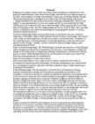
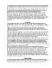
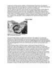
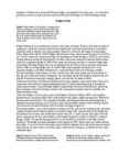
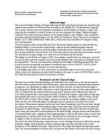
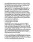
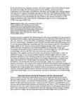
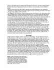
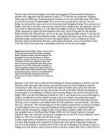
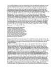
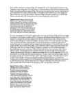
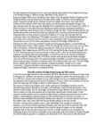
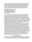
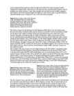
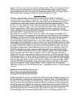
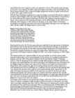
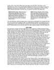
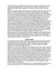
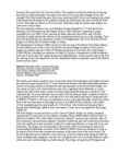
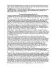
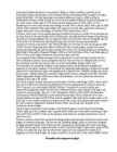
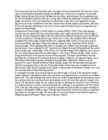


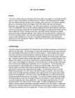
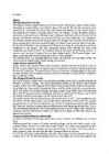


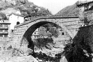


Kõik kommentaarid