EHITUSTEADUSKOND
Ehitustootluse instituut
KUIDAS MUUDAB MUDELPROJEKTEERIMINE
TERASKONSTRUKTSIOONIDE PROJEKTEERIMIST,
VALMISTAMIST JA EHITAMIST?
HOW ARE 3D AND BIM
CHANGING THE DESIGN, FABRICATION AND
CONSTRUCTION OF
COMPLEX STEEL STRUCTURES ?
EPJ 60 LT Üliõpilane:
Tanel Friedenthal Juhendaja :
Prof . Roode Liias Kaasjuhendaja:
Prof. Carrie S. Dossick Tallinn, 2010.a.
Olen koostanud lõputöö iseseisvalt. Kõik töö koostamisel kasutatud teiste autorite tööd, olulised seisukohad, kirjandusallikatest ja mujalt pärinevad andmed on viidatud . ……………………………………………..
(töö autori allkiri ja kuupäev)
Üliõpilase kood:
041399
Töö vastab magistritööle esitatud nõuetele
………………………………………………
(juhendaja allkiri ja kuupäev) Kaitsmisele lubatud
……………………
(kuupäev) Kaitsmiskomisjoni esimees ……………………………..
(allkiri) 1
EHITUSTEADUSKOND
Ehitustootluse instituut
LÕPUTÖÖ ÜLESANNE Üliõpilase kood
041399 Ehitusmajanduse ja - juhtimise
õppesuuna üliõpilasele
TANEL FRIEDENTHAL Lõputöö kood:
EPJ 60 LT Lõputöö juhendaja:
ROODE LIIAS Lõputöö teema:
KUIDAS MUUDAB MUDELPROJEKTEERIMINE TERASKONSTRUKTSIOONIDE PROJEKTEERIMIST, VALMISTAMIST JA EHITAMIST? How are 3D and BIM Changing the Design, Fabrication and Construction of Complex Steel Structures? Lõputöö teema kehtivusaeg:
31.12.2010 Lähteandmed:
Teadusartiklid ja varasem uurimustöö
2
Lõputöö sisu: Seletuskiri: 1. Sissejuhatus
2. Kirjanduse ülevaade
3. BIM Eestis
4. Metodoloogia
5. Analüüs
5.1
Seattle Keskraamatukogu 5.2 Denveri
Kunstimuuseum 6. Järeldused
6.1 Muudatused ehituskorralduses
6.1 Ehitusala õigusdokumendid
6.2 Tuleviku trendid
7. Kokkuvõte inglise keeles
8. Resümee eesti keeles
Graafiline materjal: PowerPoint
Lõputöö konsultandid: Töö osa nimetus
Konsultandi nimi
Konsultandi allkiri
Kuupäev
BIM Eestis ja naaberriikides Priit Luhakooder
22.11.2010
Hoonete kirjeldus
Ivar Talvik
22.11.2010
Lõputöö väljaandmise kuupäev:
01.01.2010 Juhendaja:
Roode Liias ………………………..
Ülesande vastu
võtnud :
Tanel Friedenthal ……………………….
Abstract How are 3D and BIM Changing the Design, Fabrication and Construction of
Complex Steel Structures?
The adoption of three-dimensional (3D) design and construction
tools have created a
remarkable shift in the
building industry. Intelligent 3D
technology in the form of
Building Information
Modeling (BIM) not only promises to
improve the notoriously
inefficient construction
process , but also opens the door for designing new geometric
shapes, which
until recently have been
considered unbuildable. Steel has been extensively
used to
build some of the most challenging architectural icons of the 21st century, due to
its low
weight and high strength in
both compression and tension.
Therefore , the steel
design and construction industry has been on the forefront of technical innovation.
The
purpose of this
study is to determine how 3D and BIM are changing the design,
fabrication and construction of complex steel structures. The thesis is
qualitative in
nature, in that it tries to determine the
effects of
virtual design and construction
based on
in-depth
analysis of two
case studies . Data were collected
during 5 interviews with people
who were intimately involved in the
projects . Background information was obtained from
professional journals,
engineering articles and conference papers. During analysis, the
data were compared to
propositions that emerged from the
literature review to determine
whether a
clear pattern was
present . A
comparison table was created to
compare the
effects of virtual design and construction of the two projects. Additionally, a
schedule is
presented to
explain the
deadline slippage on one of the case studies. The schedule is
accompanied with a data
exchange diagram to illustrate how collaboration can
affect the
project deadline.
From this analysis, it was
discovered that one of the
reasons why
there has been an
increase in the design and construction of buildings with
highly complicated
geometry is
the advent of 3D and BIM tools. The main
themes that emerged were:
• 3D and BIM increase collaboration
between different project participants;
• A
reduction in construction time is evident only when the building models are
openly shared;
• Intelligent models help to
find clashes and
reduce re-
work ;
• Models increase
accuracy during fabrication and construction;
•
Shop -
drawing review is sped up;
• Steel design
takes place in a more concurrent
fashion ;
• 3D illustrations help to explain erection sequencing;
• Building models
provide rigging information for erection crews.
The
results of this thesis illustrate the
benefit that 3D and BIM
offer for complex steel
construction projects and demonstrate an
overall trend in the construction industry. The
primary purpose of 3D and BIM is to be
able to build the structure in virtual
space before actual construction starts, so that the
majority of the potential challenges can be
successfully identified and addressed during the preconstruction phase.
Resümee Käesoleva
magistritöö põhiosa on kirjutatud Ameerika Ühendriikides Washingtoni
Ülikoolis ajavahemikus september 2009 – september 2010.
Ameerikas alustati mudelprojekteerimise
(Building Information Modelling – BIM) laialdasema kasutuselevõtuga juba ligikaudu 10 aastat tagasi ja seetõttu on sealne
keskkond ideaalne uurimaks BIM’i mõju projekteerimis- ja ehitussektoris. Antud
uurimustöö annab ülevaate mudelprojekteerimise kasutamisest kahe ülikeeruka hoone
valmimisel,
tuues ilmekalt välja selle
tehnoloogia eelised ning valupunktid. Teatud
mööndustega on ka Eesti ettevõtetel võimalik selle uurimustöö tulemusi rakendada oma
praeguste ning tulevaste ehitusprojektide elluviimisel.
Selle magistritöö ülesehitus on kooskõlas Washingtoni Ülikooli lõputööde juhendiga.
Sissejuhatusele järgneb kirjanduse ülevaade, mis käsitleb antud valdkonnas varem tehtud
uurimustöid ning avab lugeja jaoks lõputöö teema olemuse. Kirjanduse ülevaatele järgneb
metodoloogia peatükk, mis kirjeldab andmete kogumisel ning analüüsil kasutatud
metoodikat. Lõputöö põhiosa on esitatud analüüsi peatükis. Põhiosale järgneb kokkuvõte.
Kokkuvõttele on lisatud kolm peatükki, mis käsitlevad BIM’i kasutamist Eestis.
Nimetatud peatükkides näidatakse ära võimalus Ameerikas õpitut kodumaal rakendada.
Magistritöö lõpeb kasutatud kirjanduse loeteluga ja lisadega.
Esimene versioon
AutoCAD ’ist valmis 1982. aastal. Arvutustehnika kiire areng viis
projekteerimistööde puhul paberi ja pliiatsi asendumisele klaviatuuri ja hiirega.
Käesoleval hetkel kasutatakse enamikes insenerbüroodes joonestamiseks arvutit ning
pliiatsitega tehakse vaid esmaseid eskiise ning visandeid. Kuigi AutoCAD oluliselt
kiirendas joonestamist ja tõstis kasutusmugavust, tekkis 1990’ndate alguses mitmetel
arhitektuuribüroodel USA’s raskusi oma keerukate ja julgete vormide teisendamisel
kahemõõtmelisteks joonisteks. Üks esimesi rajatisi, mille puhul USA
arhitekt projekteerimisel rakendas kolmemõõtmelist
tarkvara , oli kalakujuline
skulptuur Barcelona Olümpiakülas (1989-1992). Kuna selleks hetkeks ei olnud ehitiste jaoks ühtegi
modelleerimise programmi välja töötatud, ostis arhitekt Frank
Gehry meeskond
lennukitööstuses kasutusel oleva 3D modelleerimistarkvara CATIA. Sellest hetkest alates
on mudelprojekteerimise tarkvara jõudsalt edasi arenenud ja 2000. aasta alguses ilmusid
esimesed parameetrilised 3D programmid spetsiaalselt ehitussektori jaoks.
Tuntumad hooned, mille puhul on rakendatud mudelprojekteerimist on: Guggenheim
Bilbao
Muuseum Hispaanias (1997),
Experience Music Project Seattle’s (2000),
Walt Disney Kontserdimaja Los Angelesis (2003), Seattle Keskraamatukogu (2004), Denveri
Kunstimuuseum (2006), Pekingi Olümpiastaadion (2008) jpt. Kõikide nende hoonete
puhul on maapealse kandekonstruktsioonina kasutatud terast. Teras on betooniga
võrreldes oluliselt kergem ning omab märkimisväärset tugevust nii survel, paindel kui ka
tõmbel. Terase sagedase kasutuse tõttu keerukate ehitiste kandekonstruktsioonides võtsid
just teraskonstruktsioonide projekteerijad ja ehitajad esimestena kasutusele
mudelprojekteerimise.
Selle magistritöö eesmärgiks oli kahe juhtumiuuringu põhjal selgitada, kuidas 3D ja
BIM’i kasutamine on mõjutanud teraskonstruktsioonide projekteerimist, valmistamist ja
ehitamist. Tegu on kvalitatiivse uurimustööga, käsitledes detailselt Seattle
Keskraamatukogu Seattle’s, Washingtoni osariigis ning Devneri Kunstimuuseumit
Denveris, Colorado osariigis. Koostöös Washingtoni ülikooli juhendajaga, prof. Carrie S.
Dossick, moodustati 15. punktist koosnev küsimustik, leidmaks vastus käesoleva
magistritöö lähteülesandele. Andmete kogumise käigus tuli autoril otsida inimesed kes
olid seotud nende projektidega ning viia küsimustiku põhjal läbi intervjuud. Lähteandmed
põhinevad erinevatel teadusarktiklitel, raamatutel ning teraskonstruktsioone ja
mudelprojekteerimist käsitleval kirjandusel. Kirjanduse ülevaate põhjal moodustus viis
hüpoteesi, mida kontrolliti analüüsi faasis intervjuude ja varasemate juhtumiuuringute
abiga. Uurimustulemuste kokkuvõte on esitatud tabeli kujul, milles võrreldakse omavahel
mudelprojekteerimise ulatust Seattle Keskraamatukogu ja Denveri Kunstimuuseumi
erinevatel arendusetappidel.
Kogutud andmete analüüsil selgus, et intelligentse mudelipõhise modelleerimistarkvara
kasutuselevõtt on üks eeldustest ülikeeruka geomeetriaga ehitusprojektide elluviimisel.
Uurimustöö käigus ilmnesid järgmised BIM’i eelised võrreldes tavapärase
teraskonstruktsioonide projekteerimise, valmistamise ja ehitamise praktikaga:
• Suureneb koostöö erinevate projeki osapoolte vahel;
• Intelligentsed mudelid võimaldavad leida konflikte kavandatava ehitise erinevate
osade vahel, vähendades seega ümberehitamise vajadust platsil;
• Suureneb monteeritavate detailide täpsus ja hulk;
• Väheneb jooniste kontrollimiseks kuluv aeg;
• Kiireneb liidete projekteerimine tänu andmebaasis olevatele standard liidetele;
• CNC pinkide juhised teisendatakse otse mudelist;
• Lineaarne projekteerimisprotsess asendub meeskonnapõhise tööjaotusega, kus
erinevaid hoone osasid projekteeritakse üheaegselt;
• 3D joonised aitavad selgitada montaaži järjekorda;
• Keerulistel tõstetel lihtsustub troppide asukoha määramine.
Mudelipõhine lähenemine võimaldab ehitada hoone esmalt virtuaalses ruumis,
kõrvaldades konfliktid erinevate ehitise osade vahel ning optimeerides ehitusprotsessi.
Samas oli selgelt näha, et BIM’i tõeline potentsiaal avaldub alles siis, kui arhitektid ja
projekteerijad on nõus oma mudeleid teiste ehituse osapooltega jagama. BIM ei ole
pelgalt järjekordne tarkvaralahendus vaid protsess, mis võimaldab optimeerida erinevaid
ehitusetappe.
Lähteülesandes püstitatud probleemistik on leidnud põhjalikku kajastust ning uurimustöö
põhiküsimus on vastatud. See magistritöö võimaldab Seattle Keskraamatukogu ja
Denveri Kunstimuuseumi projekteerimisel ja ehitamisel osalenud ettevõtetel saada
ülevaade mudelprojekteerimise rakendamisel tehtud vigadest ning olulistest
õppetundidest. Eesti ettevõtted võivad selles magistritöös kajastuvat informatsiooni
kasutada tulevaste koostööprotsesside kujundamisel ja tarkvaraplatformide valikul.
Õigusloomega tegelevatel institutsioonidel on praktilist kasu kindasti käesolevas töös
viidatud AIA ja AGC ehituslepingute üldtingimustest.
Autori jaoks seisneb selle töö põhiväärtus ennekõike just osapooltevahelise koostöö
olulikkuse väljaselgitamises mudelprojekteerimise edukaks elluviimiseks.
TABLE OF CONTENTS LIST OF FIGURES ............................................................................................................ 2
LIST OF TABLES .............................................................................................................. 3
LIST OF ABBREVIATIONS ............................................................................................. 4
Introduction ......................................................................................................................... 5
Chapter 1:
Literature Review ........................................................................................ 7
1.1. Last Decade in Steel Construction ............................................................................ 8
1.2. Problems With the
Traditional Practice .................................................................... 8
1.3. Building Information Modeling ................................................................................ 9
1.4. Building Information Modeling in The United States ............................................ 10
1.5. Complex Steel Structures ........................................................................................ 11
1.6. Design ..................................................................................................................... 13
1.7. Fabrication .............................................................................................................. 14
1.8. Shop Drawing Review ............................................................................................ 16
1.9. Construction ............................................................................................................ 17
1.10. Industry Response ................................................................................................... 17
1.11. Summary ................................................................................................................. 19
Chapter 2:
Methodology ............................................................................................. 22
2.1. Research Methodology ........................................................................................... 22
2.2. Sample
Selection ..................................................................................................... 23
2.3. Case Study 1 – Seattle Central Library ................................................................... 24
2.4. Case Study 2 – Denver Art
Museum ...................................................................... 26
2.5. Research Design and Data
Collection ..................................................................... 29
2.6.
Method of Analysis ................................................................................................. 30
2.7. Results and
Interpretation ....................................................................................... 31
Chapter 3:
Data Analysis ............................................................................................ 32
3.1. Project Descriptions ................................................................................................ 32
3.1.1. Seattle Central Library ................................................................................. 32
3.1.2. Denver Art Museum ..................................................................................... 41
3.2. Propositions ............................................................................................................ 52
Chapter 4:
Conclusion ................................................................................................ 66
4.1. Future
Trends .......................................................................................................... 71
4.2. BIM in Estonia and Neighboring Countries ........................................................... 73
4.2.1. BIM in
Finland ............................................................................................. 75
4.2.2. BIM in
Norway ............................................................................................. 76
4.2.3. BIM in
Denmark ........................................................................................... 76
4.3. Addressing
Legal and Contractual
Issues ............................................................... 77
4.4. BIM on the Job Site ................................................................................................ 81
4.5. Suggestions for
Further Research ........................................................................... 83
Reference List ................................................................................................................... 85
Appendix A: BDS
Interview ............................................................................................. 89
Appendix B:
Hoffman Interview ...................................................................................... 93
Appendix C: MKA Interview ........................................................................................... 97
Appendix D: Dowco Interview ......................................................................................... 99
Appendix E: LPR Interview ............................................................................................ 103
1
LIST OF FIGURES Figure No.
Page
1
Walt Disney
Concert Hall ................................................................. 12
2
Olympic Stadium in Beijing ............................................................. 12
3
Seattle Central Library ...................................................................... 25
4
The Library’s Structural System ....................................................... 25
5
Denver Art Museum ......................................................................... 27
6
Complex Steel
Skeleton .................................................................... 28
7
Structural Steel Wireframe Model .................................................... 32
8
Curtain Wall Intersection
Details ..................................................... 34
9
Detailing
Tekla Model ...................................................................... 35
10
Seele’s CNC
Manufacturing Equipment .......................................... 37
11
Point Cloud From the
Laser Scanner ................................................ 38
12
Scanned Diagonal Steel .................................................................... 38
13
Curtain Wall Mullion Installation ..................................................... 39
14
Wireframe Design Model ................................................................. 42
15
Developed Design Model ................................................................. 42
16
Complex
Connection in 2D .............................................................. 43
17
Complex Connection
Modeled in Tekla ........................................... 43
18
LPR’s 3D CAD
Shore -to-Structure
Interface ................................... 44
19
Total Station Surveying
Target in the
Field ..................................... 45
20
Modeled Targets on a
Wide Flange
Column .................................... 45
21
Duct Clashing With a
Beam ............................................................. 46
22
Upper Level Shores .......................................................................... 48
23
Rigging for a Complex
Lift Modeled in 3D ..................................... 49
24
Working Session in the Field Office ................................................ 50
25
Seattle Central Library Comparison Schedule ................................. 57
26
Denver Art Museum Data Exchange Diagram ................................. 60
27
4D Model of the Denver Art Museum .............................................. 61
28
Seattle Central Library Data Exchange Diagram ............................. 63
2
LIST OF TABLES Table No.
Page
1
Comparison of The
Cases ................................................................. 24
2
Impacts of BIM and 3D .................................................................... 68
3
LIST OF ABBREVIATIONS AEC –
Architecture , engineering and construction
BIM – Building Information Modeling
CAD – Computer-
aided design
CAM – Computer-aided manufacturing
CATIA – Computer Aided Three-dimensional Interactive
Application CFD – Computational fluid dynamics
CNC – Computer numeric
control DAM – Denver Art Museum
FTP – File
transfer protocol
GC – General contractor
HVAC – Heating, ventilating, and air conditioning
IT – Information technology
IFC – Industry Foundation Classes
MEP –
Mechanical ,
electrical and plumbing
RFI – Request for information
R&D – Research and
development SCL – Seattle Central Library
SEI – Structural Engineering Institute
VD – Virtual design
VDC – Virtual design and construction
4
Introduction With the
turn of the millennium, a revolution began in architecture, engineering and the
construction industry, aimed at implementing the latest three-dimensional computer aided
tools to improve efficiency.
Throughout history, some of the most famous
architects –
Michelangelo , Leonardo, Calatrava, Gehry, Kahn, etc. – have
built mock-ups of their
projects before beginning construction in
order to
resolve unforeseen design issues and
check for constructability. During the last decade, this model-building has moved into the
virtual world in the form of Building Information Modeling (BIM). The
idea of an
intelligent information
rich building model is not new. The identity of BIM dates
back nearly 30
years ,
while the terminology of the “Building Information Model” has been in
circulation for at
least 15 years.
Mass
production and standardization that dominated the 20th century steel industry, is
now, as a
result of the proliferation of 3D computer aided design and manufacturing
tools, turning into mass customization. The
first notable steel structure to utilize 3D
modeling was a copper-clad fish sculpture
designed by Frank Gehry for Barcelona’s 1992
Olympic village. A key
reason for Gehry’s adaptation of
digital tools was the increasingly
difficult
task of describing the innovative new designs to the contractor. His complex
three-dimensional
forms , when represented in traditional two-dimensional
plans , 2D
sections, and 2D elevations appear to be
even more complex (Lindsey, 2001).
Architects and engineers have embraced steel as their
material of choice for building
complex structures like the Guggenheim Museum, Walt Disney Concert Hall, Experience
Music Project, Seattle Central Library, Denver Art Museum, Royal Ontario Museum, etc.
The unconventional geometric forms of
these buildings, coupled with stringent
earthquake regulations meant that a fundamentally different
approach was needed to
mitigate risks, improve coordination, meet the project deadline and stay
within the
budget .
This thesis attempts to study the effects that three-dimensional software tools and
Building Information Modeling (BIM) are
having on the design, fabrication and
construction of complex steel structures. The research is based on qualitative case study
methodology, focusing on the Seattle Central Library and the Denver Art Museum. In
support of the main research question, the
following sub
questions were investigated:
5
• How are 3D and BIM affecting the structural design process?
• How are clashes detected?
• How is the steel fabrication and submittal process changing?
• How is this technology affecting steel erection?
• What tools are being used to collaborate between various project participants from
different countries?
Chapter 1 contains a review of the
relevant literature that was
found during the data
collection process. Chapter 2 discusses research methodology and explains the sample
selection and data analysis criteria. Chapter 3 contains data analysis, and is followed by
Chapter 4, which presents a comparison between the two buildings and a conclusion of
the findings. The thesis concludes with a discussion about future trends in the steel
construction industry and suggestions for further research.
6
Chapter 1: Literature Review The construction industry is complex and
dynamic and has
several constraints that
distinguish it from
other industrial sectors. Dimitri
Mitchell outlined in a September 2009
article in
Civil Engineering entitled “The Promise of Virtual Design”,
four characteristics
that illustrate the construction industry. First, there is a high degree of
complexity resulting from different
companies collaborating on a
single project. These diverse and
dispersed companies are
required to exchange
critical information during the design and
construction phases. Second, owners and other non engineering stakeholders interpret 2D
drawings differently and often have an incomplete
understanding of the planned
construction. Third, there is a high degree of uncertainty and risk caused by site
conditions .
Finally , one of the biggest issues facing the construction industry, is the
inability to discern constructability problems during the preconstruction phase of a project
(Mitchell, 2009).
To
understand the effects that three-dimensional building information models are having
on the design, fabrication and construction of steel structures, it is
important to
understand how the structural steel
components that make up a building’s
frame are
created. A
paper by Autodesk on “BIM and Digital Fabrication” describes the steel
fabrication process:
First a steel mill uses a hot-rolling manufacturing process to create stock structural steel
members . This stock material is purchased by steel fabricators who cut and prepare the
stock structural beams and columns for building construction based on shop drawings –
instructions that
describe exactly how to fabricate each
individual piece of a structure.
Once they are fabricated, the steel members are shipped to the building site and put in
place by steel erectors. The
role of the structural
engineer is to design, analyze and certify
a building’s structural frame and then create construction drawings that
document the
structural design. The structural drawings
contain only general
requirements for steel
fabrication – instructions for
typical steel connections. A steel detailer then takes those
construction drawings and applies those general connection instructions to the
specific structural components and the specific geometry of the building as represented in the
construction drawings – creating shop drawings that instruct the steel fabricator exactly
7
how to fabricate each piece of steel in the building. Shop drawings
include detailed
information pertaining to material specifications, sizes, dimensions,
welding , bolting,
surface preparation, painting requirements, etc. (BIM and Digital Fabrication, 2008).
1.1. Last Decade in Steel Construction According to Reifschneider and Santamont, less
than 10 years ago, most engineering
firms were using a structural steel design process in which the results of engineering
analysis and design were presented in a set of structural framing drawings. Generally,
these two-dimensional (2D) drawings were extracted from an engineering three-
dimensional (3D) modeling
tool ; otherwise, they were manually drawn. Subsequently,
these engineering drawings served as the contract
documents with the structural steel
fabricator, describing the detailed configuration of the structure (Reifschneider &
Santamont, 2009).
The fabricator’s
scope typically included tracking and identifying raw materials supplied
from the steel mill, arranging for the preparation of connection design calculations,
creating a detailing model used to extract shop fabrication drawings, creating computer
numerical control (CNC) data used to control the fabrication process, and fabricating and
delivering the
final assemblies to the project site.
1.2. Problems With the Traditional Practice Until recently the dominant software used by architects and engineers in the development
of project documents was AutoCAD.
Although AutoCAD has a variety of three-
dimensional drawing tools, it has been primarily used as a 2D drawing device. AutoCAD
documents have their limitations, primarily in that they lack “intelligent” properties. For
example, a beam drawn on a 2D AutoCAD document would be symbolized by a single
line. The beam
size information would be shown in text adjacent to the drawn line.
Internally, within the computer memory, no information about the beam is
known or
compiled.
8
In typical projects, the general contractor takes responsibility for procuring the steel,
arranging for fabrication, and ultimately building the structure. The contractor first selects
the shop drawing detailer and the steel fabricator. The detailer develops preliminary shop
drawings, used for ordering steel from the mill for delivery to the fabricator. Thus the
prime contractor assumes the risk for availability and delivery of steel to meet the
contract schedule. This highly linear process can add six to
eight weeks to the project
schedule for a complex structure (Whited & Gatti, 2007).
During construction, problems
tend to amplify when the wrong steel arrives at the wrong
time on the jobsite due to poor tracking by the fabricator.
Moreover , it can be very
difficult to explain complex erection schedules to the steel crew based on 2D drawings.
Additionally, explaining field discrepancies to the project managers and detailers can be
frustrating when the project only uses paper-based documents.
Shop-drawing review and submittals can take weeks and even then there might be several
issues that have not been discovered. Two dimensional drawings
allow for a very limited
clash detection process, which is based on the engineer manually comparing hundreds of
drawings and trying to visualize which
elements might
come into contact.
It is becoming increasingly common for clients to demand compressed schedules and
tighter budgets for their projects. Many engineering and construction firms are motivated
to consider concurrent design and construction
processes , otherwise known as design-
build. The integration of design and construction is a complex task that many firms are
discovering is vastly aided by the use of virtual design (VD). VD utilizes innovative tools
to create 3D parametric models of components from all design disciplines and then
assembles all of these components in a virtual space, just as they would be physically
constructed (Mitchell, 2009).
1.3. Building Information Modeling Building Information Modeling (BIM) describes the technology and process for capturing
digital information about a building throughout design, construction, and
operation . BIM
information typically contains 3D models of
real world structures with attribution that
9
allows identification, interaction, and calculation using the data and attributes associated
with the model elements (Andrews, 2009).
M.A. Mortenson Company defines BIM as an intelligent simulation of architecture,
which enables to achieve
integrated delivery. This simulation must exhibit six
characteristics - it must be (
Eastman , Teicholz, Sacks, & Liston, 2008):
•
Digital;
•
Spatial - 3D;
•
Measurable - quantifiable, dimension-able and query-able;
•
Comprehensive - encapsulating and communicating design intent, building
performance, constructability, and include sequential and financial aspects of
means and methods;
•
Accessible - to the
entire AEC/
owner team through an interoperable and intuitive
interface;
•
Durable - usable through all phases of a facility’s life.
According to Stuart Bull, a senior 3D modeling technician with
Arup Australia, “3D
modeling serves often as an interface for the data stored in a Building Information Model,
but BIM itself is
something beyond the simple geometric representation of building
spatial properties.” (Kostura, 2009).
BIM software saves the structural information associated with the drawn beam – the
beam size, length, weight, and other relevant information
including the 3D properties. In
addition ,
since the actual properties are
available ,
areas where building components clash
can be picked up by the software. Intelligent documents have the
ability to provide
material quantity data for the project (Smilow, 2007). Although the Building Information
Model is mostly conveyed in the form of a 3D visualization, it is merely a mechanism for
communicating the stored information in a concise and attractive
format (Kostura, 2009).
1.4. Building Information Modeling in The United States Although BIM has been on the
market for a number of years, it has not been adopted
industry-wide to its
full capacity. As of 2009,
approximately half of industry
10
representatives were not using any BIM software on projects in the U.S (McGraw Hill
2009).
A
survey conducted in 2008 by the Structural Engineering Institute’s (SEI) BIM
committee, revealed that out of 15,000 SEI members surveyed, approximately 65% said
that they will have to use BIM to meet clients’
needs within the next two years;
almost 80% said within the next
five years.
A survey of architects conducted from Dec. 3, 2005, to Jan. 6, 2006 by the American
Institute of Architects showed that 74% of the respondents use some level of 3D digital
modeling. Of the 74% using 3D/BIM, 98% use it for
basic visualizations and design, 34%
use it for conflict identification and 12% use it for post-occupancy facility
management (Post, 2006a).
A survey by Björk, B.C. in 2010 revealed that architecture firms are using BIM for
design-
related functions
such as building design, visualization, and programming/massing
studies. Contractors’ top three BIM use areas were clash detection, visualization, and
creation of as-built models. Use of BIM in
direct fabrication, where BIM replaces
traditional shop drawings and drives fabrication equipment, is
still limited;
however ,
almost one-fourth of the respondents utilized BIM for direct fabrication.
Geoff Weisenberger reported in a
January 2009 article in
Modern Steel Construction entitled “BIM in The Real World”, that Autodesk’s
Revit Structure, Bentley Structural
and Tekla Structures were three of the top programs; 60%, 13.5% and 9%, respectively,
of firms that said own BIM software have these programs.
1.5. Complex Steel Structures The first notable BIM projects involved such high-profile, complex structures as Los
Angeles ’s Walt Disney Concert Hall, Chicago’s Soldier Field, and Beijing’s National
Swimming
Center . The $175-million Walt Disney Concert Hall opened in 2003, but the
design work began in the
late 1980s. The complex geometric
shape of the Frank O. Gehry
& Associates design required an innovative approach. Using a software package
originally developed for the aerospace industry (CATIA, produced by the French
11
company Dassault Systems), the designers created different computer models, for use in
analysis and construction scheduling (Powell, 2008).
In non-standard projects, especially in projects incorporating compound surface
geometries, the detailed surface characteristics of the building envelope
require substantial design development of technical details to
translate the conceptual shapes into
actual building components (Leicht & Messner, 2008). Steel is often used to support
complex geometries, as it can be bent and curved into the required forms. Additionally,
the
speed of erection
cannot be matched by any other construction material.
There is no exact definition to what is a complex structure, however there are certain
characteristics, that make the design, fabrication and construction processes of a building
more difficult. For the Walt Disney Concert Hall (Figure 1) it was the undulating form
that made this project extremely complex, for the UPS Worldport in Louisville, Kentucky
it was the combination of heavy point loads in a highly seismic region and a building
design that did not allow any
lateral bracing.
Unique structures, such as stadiums and
industrial facilities require often steel in excess of 10,000 tons, exerting a tremendous
workload on structural engineers and detailers. For example the Olympic stadium in
Beijing (Figure 2), resembling a birds
nest , used 40,000 tons of steel and required 20,000
drawings to detail the twisting and turning
frames (Tuchman &
Ding -Kemp, 2006).
Figure 1. Walt Disney Concert Hall in Los Angeles (
left ) (Morrison, 2010).
Figure 2. Olympic Stadium in Beijing (Chino, 2008).
There may be
little if any time savings using 3D modeling on smaller projects, although
there may be fewer errors. However, the larger the job, the bigger the savings and the
sooner we will see a
return on investment. According to David Nelms, a detailer and
12
CAD
manager with NC Structural Detailers, “There will always be detailing
jobs where
2D technology is appropriate. And in some cases, it’s still faster than 3D.”
(Weisenberger, 2007).
1.6. Design In traditional architectural practice, contract documents, including technical plans and
specifications capture the intent of the building to be constructed. These documents are
handed over to the
builder who is
responsible for the execution of ‘means and methods’
complying with the design intent (
Allen , Becerik, Pollalis, & Schwegler, 2005). Thus,
practice conventions require
communication via working drawings that are being
translated by contractors, manufacturers, subcontractors, and consultants, for
constructability review and shop drawing development (Pietroforte, 1995).
The use of complex surfaces creates ambiguities when the designer attempts to transcribe
the model into paper format. On complex-shaped buildings, architects are representing
the global geometries of external surfaces in 3D – including roofs, cladding, glazing
systems, etc. – while
component details are supplemented with conventional 2D
drawings. What used to be a tedious computational method working with 2D segments of
a building is becoming a
visual process working with pictorial representations of the
structure, building systems, and architecture (Smilow, 2007).
The study by Ku, Pollalis, and Fischer (2007) is noteworthy in that it highlights two main
practices that architects
follow when designing complex structures in 3D. When using
‘master model technology’ the architect retains control and assumes responsibility of the
original 3D model and shares it with downstream participants, who
import the model to
develop their own work. The model is considered the primary documentation
governing the design geometry while drawings on paper are
referred to for construction detailing.
The ‘reference model approach’ coincides with the traditional distribution of design
responsibilities between the designer and recipient, where the recipients are both
responsible for the design information they create and control of their component
geometries independent of the designer’s model. With the latter approach the 3D model is
considered supplementary documentation.
13
When the architectural design has evolved to a certain point, the engineers will start
developing the structural design and performing analysis. Schinler and Nelson (2008)
argue that BIM has blurred the lines between the traditional engineer/drafter dichotomy,
with engineers picking up more coordination work using the BIM model. At the
same time, Bernstein (2009),
vice president of the Building
Solutions Division of Autodesk,
points out that BIM will not
change the use of carefully constructed analytical models
engineers have built over the years. Nor will it replace proven analysis applications like
Robobat, CSC or Sofistik.
The increasing importance of mathematics is generating a new, almost surgical precision
in building design and construction. The
tolerance for conventional structural steel for
low-
rise construction, for example, has been in the range of +/- 5 – 10mm, a standard
previously regarded as precise
among building materials. But the inability of the
computer to
accept approximations now means that metals, with their inherent precision,
can be fabricated and erected to much tolerances. This increased accuracy is accompanied
by
changes in measuring methods, both on the shop
floor and on site (LeCuyer, 2003).
The integration of CAD-CAM processes is changing the
relationship between designers,
fabricators and contractors. Formerly distanced by legal and contractual protocols, they
are now collaborating more closely, with architects either supplying the geometric
rulebook to consultants and contractors who then build their own three-dimensional
models or, alternatively, architects
providing the model and database directly to the team,
hence assuming more control and risk for what happens from that point on.
1.7. Fabrication With complex buildings, the speed of 3D modeling becomes a
major asset. According to
Rob Schoen, director of operations for
Action Steel Detailing, Inc., the increase in design-
build projects, especially those involving more than 10,000 tons of steel, is creating
“insane” detailing schedules – a situation where 3D is the only logical
answer (Weisenberger, 2007).
Difficult operations like complex end cuts of tubular steel sections – executed so
laboriously 15 years ago by spline curves set out on cardboard templates that were
14
wrapped
around each tube, which was marked and then manually cut – can now be
executed
without human intervention on the shop floor. Software performing the task of
descriptive geometry translates three-dimensional numerically-defined models into two-
dimensional fabrication data that accurately cuts components, pre-drills
holes for fixings
and
service penetrations. While producing more sophisticated steelwork, the skilled
labor content is being reduced overall and focused increasingly upon the final
assembly of
CNC milled components (LeCuyer, 2003).
The 3D steel detailing model is becoming a
deliverable to fabricators and erectors. Not
only is it easier for the detailer to visualize the complex geometry and connections of
today ’s projects via a 3D model, it is also beneficial for shop production, project
managers, and field superintendents. With BIM, 2D drawings are just one portion of the
deliverable. CNC-driven machinery is becoming more powerful and affordable, and
feeding these machines with accurate fabrication information as
early as possible in the
design process is vital to shop production. More and more detailers are being instructed
by fabricators to provide CNC files as well as an electronic bill of materials for shop
equipment and material management systems. What may have taken two weeks with shop
personnel manually entering data is now being
done in a day or two with information
being directly downloaded to the CNC machinery from the 3D detailing model
(Weisenberger, 2008).
Once the steel details are
complete , the fabrication model can be used by the design team
or the contractor for the purpose of 4D modeling as well as clash detection with other
building disciplines (
BIM and Digital Fabrication, 2008).
Early Steel Detailing is a process, where the development of structural steel shop
drawings takes place concurrently with the development of the construction documents
(Trammell, 2009). In such an approach the steel detailer
works directly with the design
team in an effort to produce the first sequence of shop drawings simultaneously with or
immediately after production of contract documents for the project. These drawings can
be used to obtain a more exact quote from a steel fabricator and then
begin the process of
fabricating steel for the job immediately without waiting for shop drawings to be
developed by the fabricator or detailer (Farrow, 2007). By
sharing the structural
engineering model with the detailer, a lot of time and
money can be saved by not having
to recreate a detailing model from 2D drawings.
15
1.8. Shop Drawing Review Adopting the BIM approach entails a migration from paper to electronic data exchange.
There is a growing
interest in the design and construction industry to reduce the
amount of paper used to review structural steel shop drawings, and multiple owner and contractor
organizations are encouraging digital
approval processes instead of paper (Weisenberger,
2007).
Many steel detailers create 3D models of steel structures, which are then used to produce
shop drawings and eventually to fabricate the steel. These same 3D models can also be
used during the review process to various extents, depending on the method that works
best for the design team. Michael Gustafson, the engineering product manager for North
America at Tekla Inc., has outlined the following three workflows (Quinn & Willard,
2010):
1.
2D (traditional method) – The 2D workflow is the traditional method by which
most shop drawings are reviewed. Typically, 2D structural steel shop drawings are
mailed to the engineer of
record , who reviews
them in conjunction with their 2D
construction drawings and then returns them to the fabricator via mail.
2.
2D-3D (combination of traditional method and new technology). In the 2D-3D
workflow, a 3D model is used as an aid to the review process, but 2D shop
drawings are still the method used to convey approvals and comments.
3.
3D (full model review using new technology). In the 3D workflow, the actual
model from the fabricator/detailer is used by the engineer to provide approvals
and comments back to the fabricator/detailer.
For example, Rutherford and Chekene, a California based engineering
firm , working on
the Sutter General Hospital in Sacramento, an 11-story building utilizing more than 5,000
tons of steel was able to
avoid printing approximately 30,000 sheets of drawings
thanks to
3D shop drawing review. With the shop drawings done sooner, the mill order can be
submitted sooner, the fabrication can start sooner and the steel can be erected sooner
(
BIM and Digital Fabrication, 2008).
16
1.9. Construction The steel erector and the general contractor can use 3D models to plan construction,
verify field layout and illustrate construction schedules. A Stanford
University study by
M. Fischer and J. Kunz (2004) titled “The Scope and Role of Information Technology in
Construction” provides an example how three-dimensional building information models
were used during the construction of the Walt Disney Concert Hall. During the
construction phase, the general contractor, M.A. Mortenson, used 4D models to
coordinate the workflow of their subcontractors and site logistics, and to validate early on
that their thinking of the project’s overall sequencing was
correct . The project’s general
superintendent , Greg Knutson,
estimated that for every hour spent working on the
schedule, about six hours were needed to communicate the results. 4D models
allowed to
reduce that time while increasing the amount of subcontractor feedback and buy-in.
Once a
month in a subcontractor coordination
meeting , the 4D models were used to
preview the scope of work for the upcoming 90
days . During those meetings, Mortenson
and the subcontractors studied the placement of the cranes to minimize crane movements
and to ensure that the cranes
could reach all areas of work as required by the schedule.
Because of the complexity of the project, 4D models proved very helpful in convincing
various authorities that the general contractor had an accurate schedule. Since the
County owned the parking garage on which the concert hall was constructed, the County needed
to approve the steel erection plan. Although Mortenson had generated a detailed plan, the
County was not clear on the phasing of the cranes. After several weeks of meetings with
the County that did not yield the desired approval of the erection plan, Mortenson showed
the 4D model of the erection sequence to the County officials. In 15 minutes the officials
were able to understand more about the erection plan than they had been able to grasp in
many afternoons of working through the binders (Fischer & Kunz, 2004).
1.10. Industry Response Industry publications including case studies,
magazine articles, reports and webinars have
illustrated the change, which three dimensional building information models have
brought about. Several themes on BIM and the effects this technology is having on the design,
17
fabrication and construction of complex steel structures have emerged from a review of
these industry publications. The following excerpts illustrate these themes:
•
Time – WSP Cantor Seinuk, an internationally recognized structural engineering
firm based in New York, has been using BIM models as a
basis for their bidding
documents. When all steel bidders are
given a 3D model of the structure, they
automatically have an accurate tonnage and piece count. Moreover, at the time of
the contract
award , a fully developed model is
already available and time is not
wasted on creating a model based on 2D plans. The positive feedback from bidders
has confirmed that this process expedites bidding and the creation of shop drawings.
With a highly complex structure, such as the Mets Stadium in Queens, New York,
WSP reduced the shop drawing process by approximately one month (Smilow,
2007). Additionally, projects with extremely compressed schedules are seeing
considerable time savings by using Early Steel Detailing. With this method, steel
erection can begin immediately following the
release of construction documents.
Matt Trammell, the structural engineering manager at TRC Worldwide Engineering
Inc., based in Brentwood, Tennessee, has estimated that at least two months of
construction time was eliminated in a
recent hospital project due to the
implementation of Early Steel Detailing (Trammell, 2009).
•
Cost – An article by C.J. Carter and T.J. Schlafly titled “$ave More Money” (2008)
lists three items that make up a cost estimate of a steel structure:
o Material
costs 25%
o Fabrication and erection labor costs 60%
o Other costs 15%
Therefore, in today’s market, labor in the form of fabrication and erection
operations typically accounts for approximately 60% of the total constructed cost. In
contrast, material costs only
account for approximately one quarter of the total
constructed cost. The greatest cost savings are achieved when the design is
configured to simplify the labor associated with fabrication and erection (Carter &
Schlafly, 2008). This is facilitated by 3D constructability analysis and 4D
construction
planning and erection sequencing.
18
•
Request for information (RFI) – On large projects with complex geometries,
hundreds, if not thousands requests for information are required. However, using
BIM effectively can dramatically improve the ability to
share data, which results in
a significant reduction in RFIs.
•
Rework – When the building is first designed in a virtual environment, the detailer
is able to verify that various elements converging on one point fit together properly.
The A-3 rocket test
stand at Stennis Space Center in Mississippi, has up to 16
different structural members connecting at one point, requiring a very slim margin
of
error . However, thanks to 3D modeling, less than 1% rework of all connections
had to be performed in the field (Weisenberger, 2009).
•
Collaboration - Under a traditional design-bid-build contract, designs are moved
sequentially from architect to engineer to fabricator, with little interaction until the
project breaks
ground and problems start to rise (Powell, 2008). The geometric
logics of fabrication and construction may introduce uncoordinated changes to the
design intent of a 3D model created by the architect if not facilitated by an
appropriate communication
platform and protocol (Leicht & Messner, 2008).
Virtual design essentially closes the gap between design and construction and
significantly facilitates collaboration among design and construction
teams (Mitchell, 2009).
1.11. Summary The main theme that emerged from the literature review of academic and industry
publications is the importance of collaboration that is needed to facilitate the design and
construction of a complex structure. Adopting BIM necessitates a closer form of
collaboration (Eastman et al., 2008). The architectural firm has a two-way
link in the
collaboration. On the one side are the design consultants - structural, mechanical, etc. On
the other side are the general contractor and many types of subcontractors and fabricators
providing early input of constructability, so that there is a smooth transition from design
intent into realization. Using the building model to facilitate this integrated team will
allow earlier and more concurrent use of their knowledge in less linear and more
19
concurrent settings, thus addressing multiple factors beyond those of constructability. A
key aspect for collaboration in early stages is to produce appropriate level of details to
allow accurate planning by the subcontractors while maintaining flexibility in the design
details (Elvin, 2007).
The subcontractors who
manage the production process are the
ultimate consumers who
should receive information from the designer. Thus, designers need to
agree with the
contractors who will use the design model in their production processes, on the level of
detail in the model, the data format, and the data compatibility between the CAD/CAM
platforms. Sophisticated subcontractors have adopted 3D technologies to improve their
fabrication procedures, and are in a well-equipped
position to collaborate via model-
based environments. (Ku, M., Pollalis, & Fischer, 2008).
However, there are currently several impediments, that
limit the use of building
information models to their full extent. In many cases, paper based documents are still
seen as the primary means of communication.
Functional differences and capabilities of CAD programs impact the communication
strategies of complex-shaped architecture. When the architect’s files and the fabricators’
files are not directly compatible, it becomes
necessary to translate between the architect’s
model and the recipients’ platforms. Typically, interchangeable file formats are supported
by commercial software, yet the conversion is not flawless and often
requires additional
processing (Ku, M., Pollalis, & Fischer, 2008).
The interoperability issues of the design/construct community are mirrored in the
structural engineering profession. There are dozens of analysis and design (A&D)
programs available for modeling various aspects of a structure. However, the graphical
representations of the engineer’s designs traditionally have been rendered in a CAD-
based set of design drawings. There is little, if any, data embedded in an AutoCAD file
that can be used by clients or other members of the design or construction teams. A
significant process improvement can be achieved by integrating the models created for
analyzing and designing a project with a Building Information Model (Burt, 2009).
As discussed
above , BIM and 3D modeling are dramatically changing the way we build
our infrastructure. Although, the technology that supports virtual design and construction
has been on the market for at least a decade, it has been used sparsely on traditional
20
projects. To get a better understanding of the full capabilities of BIM, we need to
look at
highly complex structures, that could not have been built utilizing only conventional
building methods and processes. However, there has been little research that focuses on
the use of building information modeling during the design and construction of complex
steel structures. Therefore, this research is meant to provide an analysis of the emerging
tools and methods used during the construction of two very challenging architectural
icons in the United States.
21
Chapter 2: Methodology The purpose of this thesis is to identify the effects that 3D modeling and BIM are having
on the design, fabrication and construction of complex steel structures. The purpose of
this chapter is to (1) describe the research methodology, (2) explain the sample selection,
(3) describe the procedure used in designing the tool and collecting the data, and (4)
provide an explanation of the procedures used to analyze the data.
2.1. Research Methodology No documented process or quantitative data of the impacts that BIM and 3D modeling are
having on complex steel structures was found in a review of the literature. As a result, a
qualitative approach was used. Qualitative data provides in-depth knowledge in the form
of words
rather than numbers. This thesis is qualitative in that it tries to determine the
effects of 3D and BIM on the traditional construction practices through the experiences
and stories of the participants.
Qualitative methods allow for the researchers to bring their personal-self into the research
along with their researcher-self. Biases, values, and interests are acknowledged and
included in the reporting. Qualitative research
looks at the research setting from the
viewpoint of
deep understanding rather than micro-analysis of limited variables. Instead
of trying to
prove or disprove a hypothesis, qualitative research looks for themes,
theories, and general patterns that emerge from the data. Qualitative research is
“hypothesis-generating” rather than serving to test a hypothesis (Merriam, 1988).
There are a variety of terms used to describe qualitative research methods such as
ethnography, field methods, qualitative inquiry,
participant observation, case study,
naturalistic methods, and responsive evaluation. The case study research method was
chosen as the most appropriate way to answer the following research questions:
1. How are 3D and BIM affecting the structural design practices?
2. How are clashes detected?
3. How is the traditional steel fabrication process changing?
22
4. How are the detailers using the new tools?
5. How are 3D models changing the submittal process?
6. What is changing during steel erection?
7. What tools are being used to collaborate complex designs between various project
participants from different companies?
The case study method and design is well-suited to this thesis because of its ability to
answer the research questions appropriately. “The case study is preferred in examining
contemporary events but when the relevant behaviors cannot be manipulated” (Yin,
2009).
Yin’s (2009) definition of a case study is:
“...an empirical inquiry that investigates a contemporary phenomenon within its real-life
context , especially when the boundaries between phenomenon and context are not
clearly evident...[It also] copes with the technically distinctive situation in which there will be
many more variables of interest than data points, and as one result relies on multiple
courses of evidence, with data needing to converge in a triangulating fashion, and as
another result benefits from the
prior development of theoretical proposition to
guide data
collection and analysis.”
2.2. Sample Selection The two cases are considered relevant and appropriate because they both
represent highly
complex steel structures, which could not have been built within a reasonable timeframe
and on budget without the extensive use of the latest model based software available at
the time. The complex geometrical form of the Seattle Central Library and the Denver Art
Museum created unique challenges for everyone involved in the projects. Hoffman
Construction, the general contractor on the SCL, and Mortenson Construction, the GC on
the DAM are both considered pioneers in the use of virtual design and construction
techniques in the United States. The
fact that the steel detailer, erector and the structural
engineering firms were out of state and that the architects were from
Europe , created the
23
need for virtual collaboration. The buildings were completed two years apart, which is
sufficient to illustrate the advances in technology and the adoption
rate of BIM tools.
Table No. 1. Comparison of The Cases.
The Seattle Central Library The Denver Art Museum Location 800 Pike Street
100 W 14th Ave
Seattle, Washington, USA
Denver, Colorado, USA
Construction period
Fall 2001 – May 2004
July 2003 – October 2006
Total project cost
$165.9 million (includes $10
$110 million (Hamilton
million for the temporary
Wing $75 million, added
Central Library, construction
scope $35 million,
$112 million)
including parking structure)
Steel tonnage
4,644t
2,740t
General Contractor
Hoffman Construction
M.A. Mortenson Company
Company
Architect
Rem Koolhaas (Office for
Studio
Daniel Libeskind
Metropolitan Architecture)
and Davis Partnership
and Joshua Ramus (LMN
Architects - A
Joint Venture
Architects) – A Joint Venture
Structural Engineer
Magnusson Klemencic
Arup
Associates
Steel Detailer
BDS Steel Detailers
Dowco Consultants
Steel Erector
The Erection Company
LPR Construction Company
Building size
412,000
square feet (38,300
146,000 square feet (13,564
m²)
m²)
2.3. Case Study 1 – Seattle Central Library Designed by Rem Koolhaas and Joshua Prince-Ramus of OMA/LMN, this building was
awarded a Platinum Award in 2005 for innovation and engineering in its "structural
solutions" by the American Council of Engineering Companies of Washington. While
most traditional towers employ a proportioned column
grid , the Central Library’s
structure uses asymmetrical placement of perimeter and
interior trusses, in
places cantilevering out to bear on opposing sloped steel box columns. The concrete
core and the
concrete foundation walls on three sides act to tame the twist that the off-set platforms
naturally impose, while the exterior steel diamond grid system
behind the
glass "net"
serves as the building's seismic support system (Figure 3).
24
Figure 3. Seattle Central Library (Martínez, 2010).
Figure 4. The Library’s Structural System (Post, 2003).
25
The architects’ designs called for
minimal number of
vertical columns, no columns in the
corners, and as few columns as possible. The project’s
success depended on
making a 12-
story, all-glass building appear to “float” without support. As Seattle is
located in Seismic
Zone 3, codes require the structure to accommodate significant lateral as well as gravity
loads. MKA (working with Arup) proposed two separate, layered structural systems
(Figure 4). The first system,
multi -story-deep perimeter platform trusses supported by
carefully positioned
sloping columns that maximize counterbalancing opportunities carry
the building's gravity loads. The second system, a unique diamond-shaped steel grid,
serves quadruple duty: it resists wind and earthquake loads, interconnects the platform
trusses, serves as the interior architectural finish and supports the glass curtain wall
(Taylor and Stenning, 2005). Specially designed
slip connections laterally
join the steel
grid to the platform trusses. The connections merge the two structural systems, while
preventing the transfer of gravity loads into the grid (Seattle Central Library, 2005).
The building is framed in concrete from the spread footing foundations, 10 ft (3 m) below
the west
grade , to level three, which is at grade on the
east . Above level 3 the structure is
all steel. A mat foundation supports the 213-ft-
tall (65 m) concrete core, in the southwest
quadrant of the footprint. Every platform column around the perimeter is raked and
architecturally expressed. Each offset platform has a perimeter steel truss on either two or
four sides, matching its story
height . The three-story belt truss for the books platform is
the hardest working. The grid knits the platforms together, preventing them from tipping
over. Made from 12-in.-deep (305 mm) wide-flange members, the grid works like a giant
braced frame, collecting seismic forces from each platform, carrying them across the grid
to the next platform and ultimately to the concrete base. The building is designed for site-
specific ground motions based on an earthquake with a 500-
year return period (Post,
2003).
2.4. Case Study 2 – Denver Art Museum Designed by Daniel Libeskind in a joint venture with Denver-based Davis Partnership
Architects, the angular structure incorporates no true vertical surfaces. Without the
support of vertical walls or columns – or even a flat
roof – to work with, the structural
26
engineers, from the Los Angeles office of Arup, were challenged to design a support
system that would
hold together the outward-leaning walls and fashion the inherently
unstable forms into a stable structure (Figure 5).
Figure 5. Denver Art Museum (McClellan, 2008).
A tightly controlled environmental system to protect the works of art was required, and
that system would have
special ductwork for various zones that would run from
centralized mechanical rooms to the galleries. Like the structural system, the ductwork
could not follow typical vertical and horizontal paths. All lateral loads are resisted by
latticelike steel bracing on the exterior walls; some additional bracing runs through the
interior. To avoid the angled walls from deflecting during the construction they had to be
shored. The
challenge was to determine which geometry to use so that when the gravity
loads were imposed on the structure it would deflect to the desired architectural geometry
(CE 06, Dec).
Due to the severely inclined walls and large cantilevers, it was decided early on that the
dead weight of the building would need to be minimized, thus making structural steel the
material of choice. The walls of the building generally
lean outwards, so to some extent,
the lateral loads balance each other. Thus the floors act as tension ties for the inclined
walls, with the steel beams helping with tension and compression. However, where these
forces are not balanced they must be taken to ground through the building’s lateral
27
stability system. This requirement, together with the architect’s desire for column-free
spaces inside the building,
lead to the
decision to place as much of the structure as
possible within the inclined walls. As a result, lateral loads are imposed on the structure
that would exceed those potentially seen in regions that experience high levels of seismic
activity, even though Denver is not located in a zone of high seismic activity.
Figure 6. Complex Steel Skeleton (Eastman, n.d.).
The floor system consists of steel with a composite floor
deck . The design of the floor
system was complicated by the forces of the inclined structural walls, which create very
significant in-plane forces under dead
load . To deal with these forces, additional
reinforcement was required within the concrete floor slabs. In areas of particularly high
stress , the
metal deck was replaced with a ½ in. (12.7 mm) steel plate welded directly to
the beams. Similarly, a substantial amount of steel diagonal bracing in the roof plane was
required to supplement the roof framing in areas where concrete diaphragms were not an
option (Figure 6).
28
2.5. Research Design and Data Collection Available literature on the two projects and interviews were used as primary sources of
information. A research tool was developed based on the findings from the literature
review and earlier research. At the heart of a good case study are a series of propositions
– a statement directing attention to something that should be examined within the scope
of the study.
The propositions for this thesis are:
• Intelligent computer aided design and construction tools help to achieve the tight
tolerances required to design and build a complex steel structure;
• Building Information Modeling helps to reduce RFIs;
• 3D and BIM produce cost-savings and reduce project duration;
• Intelligent virtual models reduce clashes and provide constructability input;
• Working with BIM models
increases collaboration between different project
participants.
To test these propositions, interviews were conducted with industry professionals who
were intimately involved in the two cases. The type, amount, and configuration of
interview questions were refined in a series of iterations between March 1 and April 15,
2010.
The interviews, which
took place in April and May 2010, were designed to create a
conversation about the respondents’ experience with Building Information Modeling on
highly complex steel projects. An interview setting was chosen to elicit an atmosphere in
which the respondents could
feel safe to speak freely.
There were three types of interviews: (1) one
face -to-face interview, which was tape-
recorded; (2) three telephone interviews during which the researcher took notes; and (3)
one interview response using electronic mail. Each interview consisted of 15 major
questions, see Appendix A-E, plus a few additional questions where clarification was
needed. Each respondent was assured of confidentiality.
The interviews were broken down into five sections. The first section focused on general
information related to the role of the company, and the role of the
person being
interviewed. The second section included six design related questions focusing on the
29
model creation and sharing workflow with other trades. The third section consisted of
three questions related to steel fabrication, helping to determine how 3D and BIM were
used during the shop drawing review process. The fourth section included five questions
about the implementation of 3D and BIM during the construction phase. The interview
concluded with 5 wrap-up questions about the general trends in the industry, giving the
interviewee an opportunity to share his or her thoughts, which were not covered by the
previous questions.
In addition to the interview data, some respondents
provided previously unpublished
papers and articles that were not discovered during the literature review. This additional
material proved to be invaluable by offering detailed information about the use of 3D and
BIM on these two projects.
2.6. Method of Analysis Data analysis involves organizing what you have seen, heard, and read so that you can
make sense of what you have learned. Working with data, you describe, create
explanations, pose hypotheses, develop theories, and link your story to other stories
(Glesne, 1999). Data collected from the interviews, and examination of industry
publications were organized under categories based on the emergent themes. Since
qualitative data analysis does not provide any fixed formulas or cookbook recipes to the
researcher, much depends on the investigator’s way of thinking about the data, along with
consideration of alternative interpretations and presentation of evidence (Yin, 2009).
Yin (2009) regards the primary modes of data analysis in a case study as:
• Pattern matching - the search for patterns by comparing results predicted from
theory or the literature;
• Explanation building - in which the researcher looks for casual links and/or explores
plausible or rival explanations and attempts to build an explanation about the case;
• Time-series analysis - in which the researcher traces changes in a pattern over time;
•
Logic models - in which the key ingredient is the existence of repeated
cause and
effect sequences, all linked together.
30
Collected data were linked to the propositions through analysis. For case studies, one of
the most desirable techniques to connect data to propositions is by using a pattern-
matching logic. Pattern matching requires using past experience, logic, or theory before
the data collection begins to specify what we expect to find. The analysis then compares
actual findings to expectations. When the findings fit, the pattern is confirmed. When the
findings do not fit, the researcher adjusts the expectations or elaborates them, building a
subroutine that can explain the unexpected findings.
2.7. Results and Interpretation The following chapter is about data analysis. It is divided into two parts:
Part I – Project
description, and Part II – Connecting data to propositions. The first part will illustrate the
use of 3D and BIM during the design, fabrication and construction phases of the Seattle
Central Library and the Denver Art Museum. The second part of the analysis will look at
the five propositions and determine whether they can be confirmed or rejected. When a
clear pattern is not present, an explanation will be provided to clarify the findings. The
last chapter of this thesis – conclusion – includes a comparison between the two cases and
an overview of the latest trends regarding 3D & BIM in the steel construction industry.
The conclusion includes three subchapters written after the
author returned to Europe to
illustrate how BIM is affecting the AEC industry in Estonia and neighboring counties.
Also included is an overview of how construction contracts both in Estonia and the U.S.
are being updated to address the specific issues regarding building models. The last
chapter concludes with suggestions regarding further research.
31
Chapter 3: Data Analysis 3.1. Project Descriptions 3.1.1. Seattle Central Library Design The architects did not share their 3D models with the general contractor (Hoffman) and
therefore all the subsequent models had to be created based on 2D AutoCAD files.
Nevertheless, the structural engineer (MKA), the curtain wall design/builder (Seele), the
general contractor, the steel detailer (BDS) and the mechanical subcontractor (McKinstry)
all utilized 3D modeling on this project (Figure 7).
Figure 7. Structural Steel Wireframe Model (Dale Stenning, personal communication,
May 10, 2010).
32
Hoffman decided to have the curtain wall subcontractor design the aluminum mullion
system first and then align the diagonal steel behind it. The original plan was to use
Seele’s 3D wireframe model as a basis for creating the Tekla model used for detailing and
fabricating the structural steel. For a typical building, the curtain wall and structural steel
are detailed in parallel. However, the Library’s unique geometry and small tolerances
prohibited this approach. A cumulative tolerance of ½
inch (12.7 mm) was set for the
façade system. Seele’s model needed to be extremely accurate, because the structural
steel would be offset from the face-of-glass. This meant that the steel detailer had
minimal
room for error. The goal was to save the bulk of the tolerance for fabrication and
erection.
The next priority was to establish a common frame of reference, so that all involved
parties were dimensioning to the same points. Since the diamonds were a standard size,
the architects (OMA/LMN) developed a “key diamond” approach, with the grid layout
referenced from a single diamond on each face. Hoffman and Seele did modeling to array
the grid geometry up each building face and across the folds, so the architects could
select the optimal diamond grid relationships at the corners. The key diamond was set at a
correlating location, with the grid lines and finish floor elevations providing x,y,z
coordinates (Stenning & Taylor, 2005).
Based on the key diamond, Hoffman created a uniform coordinate systems for
transferring and sharing files. From this, Seele built a preliminary wireframe model
which, after auditing and acceptance by the design team, was
later developed into an
intelligent 3D
object model containing all the curtain wall components. The model
included production information for the computer numerically controlled fabrication
equipment.
33
Designing the
fold transitions proved to be
most challenging for Seele. At some folds, the
architects wanted a gutter; in other places a
point fold was desired. No two folds were
alike, due to the building’s geometry and
asymmetry, every time a fold line was shifted,
it changed the geometry of the entire building
face. Each fold decision impacted the
Figure 8. Seele’s Computer Rendering of
detailing, design and construction of the Curtain Wall Intersection Details (Stenning
various joins, including steel connections. & Taylor, 2005).
Seele developed details for every single
condition of steel converging at the corners for
review by OMA/LMN and MKA (Figure 8). Ultimately, mockups were built of two of
the most complex building corners, as well as many of the fold line conditions, for final
architectural approval (Stenning & Taylor, 2005).
Contractually the curtain wall designer Seele, was obligated to
hand over their object
model to the steel detailer, BDS, but that
never happened (Appendix A). Seele ultimately
gave their wireframe model to Hoffman, with a
liability waver. Therefore the steel
detailer
ended up creating their own 3D model, which
became the main model on this
project (Figure 9). BDS used Tekla Structures (formerly known was Xsteel) to model the
complex structural elements converging at different angles. Since the glazing would be
applied directly to the diagonal steel, it was mandatory to have all the geometry in 3D.
Instead of receiving a model from the curtain wall designer, as was originally anticipated,
the steel detailer ended up sending their model to Seele so they could verify that the
geometry of the diagonal steel and the curtain wall mullions lined up perfectly.
34
Figure 9. Detailing Tekla Model Showing the Diagonal Steel Connection to the Book’s
Platform Truss (Dale Stenning, personal communication, May 10, 2010).
Once the entire building was modeled in Tekla, MKA and Hoffman assessed
constructability for all
corner conditions. Instead of detailing every one of the
thousand joints, MKA developed standard parts with individual details applicable to several
conditions. The detailing team was instructed to use Detail 1 if they ran into Condition A,
B or C, detail 2 if Condition D, E or F, etc., thereby covering a wide range of conditions
with a relatively small set of details.
Once the detailing team had a partially developed Tekla model, it was handed off to the
MEP subcontractors. They incorporated the mechanical, electrical and plumbing routing
and penetrations and returned the revised model back to the steel detailers. BDS then
trimmed the details around the MEP penetration points. MKA reviewed the model to
compare actual penetrations with those originally anticipated and to ascertain any
structural impacts. A second kit of parts was developed by MKA for conditions requiring
revision, with the detailing team again selecting and applying the appropriate solutions
(Stenning & Taylor, 2005).
MKA did localized 3D modeling to analyze critical structural conditions, but they did not
develop a BIM model of the entire building. They used Microstation for 2D drafting,
Triforma for 3D modeling and SAP2000 for structural analysis (Appendix C).
35
Fire safety proved to be another design aspect that benefitted from the use of computer
aided tools. The building is fully sprinklered, but smoke control for large
open spaces
proved to be a challenge. The code called for 800,000 cfm (378 m3/s) of exhaust, which
would have been costly, requiring many louvers for makeup air. A computational fluid
dynamics (CFD) model for smoke flow was created by the San
Francisco office of fire
protection engineer Arup Fire. That model was used to convince officials that only
275,000 cfm (130 m3/s) was needed. The CFD
graphic gave the fire department its first
understanding of how the building worked (Post, 2003).
Even though the project did not have an all encompassing BIM model, 3D tools were
used throughout the design phase. MKA created a three-dimensional wireframe model for
structural analysis and Seele used their wireframe model to design the curtain wall.
Seele’s wireframe model, accompanied with a liability waiver, was used as the basis for
creating the intelligent Tekla model, showing all the diagonal steel as well as the complex
connections. Ambiguity in the contract language, as to who was
supposed to share which
models created a certain amount of confusion and delays on this project. Because the
diagonal steel and the curtain wall were being designed in different countries, it was
absolutely vital to have an accurate 3D representation of the entire structure. Achieving a
combined facade tolerance of ½ inch (12.7 mm) using 2D documents would have proven
extremely difficult. Thanks to powerful visualization capabilities of 3D modeling
applications, engineers were able to develop kit details for a multitude of connections
used repetitively throughout the building. Trying to design those connections in 2D would
have had a significant impact on the overall project schedule. In addition to using 3D to
analyze different load combinations, a CFD model provided
valuable information in
determining the amount of air required for the fire safety system.
Fabrication Seele, located in Germany, was responsible for the cladding preconstruction
services , the
production and installation of 128,000 square feet (11,900 m2) of exterior cladding
comprising of more than 6,500 glass panels and 30,000 anodized aluminum profiles. The
building’s faceted
skin geometry required extensive 3D engineering as the facade
surfaces of aluminum extrusions, silicone gaskets, triple-glazing panels, pressure
plates ,
gutters and closing panels join in up to five different angles at particular node points. A
36
comprehensive digital 3D model of the entire facade provided the manufacturing data for
all prefabricated elements as well as the related labeling information, packing lists and
transportation schedules (Menges, 2006).
Figure 10. Seele’s CNC Manufacturing Equipment (Menges, 2006).
The fabrication and construction of building façades made from rigid materials such as
metal and glass require a great range of
forming and fabrication processes. Seele used a
wide range of different CAD/CAM processes. Metal and aluminum profiles were cut by a
numerically controlled saw permitting the rapid production of different length work
pieces (Figure 10). A special CNC drilling and welding unit created holes and fixed stud
poles according to digitally defined distance and angle information. Sheet material was
automatically allocated, prepared, cut and marked by a digitally controlled laser. At
Seele’s
factory in Germany, the cutting laser was combined with a digitally controlled
shelving system that automatically selects, prepares and
positions the material on the laser
bed to increase workflow efficiency. Another
machine facilitated the CNC bending and
folding of sheet metal materials.
Seele’s 3D model of the aluminum mullion system was used to control manufacturing
equipment and even to determine the transportation schedule. Using the design model in
the fabrication process, not only increases accuracy, but it also saves time in not having to
create a separate set of 2D instructions for the CNC machines. The same applied to the
structural steel model – since all the connections for the diagonal steel were fully defined
in Tekla, welders were able to attach all of the gusset plates in the fabrication shop. The
shop drawings were created inside Tekla, thus avoiding the laborious task of manually
creating yet another set of drawings.
37
Construction MKA was
hired by the general contractor, Hoffman Construction, to build a 3D structural
model showing the sequence of steel erection. That model was included in the bid
documents to all the potential steel bidders. It showed approximately 320t of temporary
steel and the correct erection sequence. It was imperative that a certain erection pattern
was followed, otherwise the steel would have corkscrewed down on itself before the
workers had time to fully
weld up all the connections and brace the structure. In addition
to explaining the complex erection sequence, the model proved valuable in obtaining an
accurate up
front price early on in the project (Appendix B).
The steel erector, TEC used two separate models to plan their work: 1) the temporary
steel model from MKA; 2) the Tekla model from BDS. During the construction of the
Seattle Central Library, 4D sequencing was in its infancy, and they did not have a 4D
model that tied the geometry to an electronic schedule. Also the site planning process
followed the traditional 2D
routine – tower crane location and hoisting ranges were
determined in AutoCAD.
Figure 11. Point Cloud From the Laser Scanner (left).
Figure 12. Scanned Diagonal Steel
(Dale Stenning, personal communication, May 10, 2010).
The steel erection process called for ongoing and extremely accurate surveying. This was
the first project, where the general contractor used laser scanning, a cutting
edge technology developed by the U.S. military to link satellites under their
Star Wars
program . After erection, Hoffman scanned every diagonal steel section from at least three
separate points, then examined the graphical reports for areas where the Tekla model and
the erected surface varied by more than ½ inch (12.7 mm) (Figure 11, 12). After quickly
38
pinpointing these locations, Hoffman performed field adjustments by either pushing or
pulling the steel into place. Once the steel was within acceptable tolerances, it was
permanently bolted. Hoffman adopted a routine of hanging steel in the morning, laser
shooting it in the afternoon, analyzing the reports in the evening, then reporting the
results to the ironworkers the next morning. Any panels that had to be adjusted were
rescanned to verify the new location (Stenning & Taylor, 2005). This innovative
approach enabled Hoffman to find out where the catenary was and preinstall shims prior
to assembling the aluminum mullion system that rests on the diagonal steel (Figure 13).
Figure 13. Curtain Wall Mullion Installation (Post, 2003).
This project did not have a single comprehensive model combining geometry from all the
different trades. The architect refused to share their model due to liability reasons and
only provided 2D documents. Without a complete model from the architect, BDS was
tasked to finish the design of many details, resulting in a significant number of RFIs. The
detailing model was constantly
modified based on RFIs to reflect all the design changes.
At the end of the project, the detailers Tekla model became the as-built and was handed
over to the owner. This as-built model will probably prove very valuable in the future for
major maintenance operations and facility management
purposes .
39
Despite an increase in RFIs, 3D models were very valuable in the construction phase,
which compared to the design stage, has traditionally experienced less innovation. On this
project, the unstable nature of the large cantilevered platforms necessitated the creation of
a 3D steel erection animation. In addition to the structural members, the movie clip
showed the sequencing of 320t of temporary steel, which were needed to brace the
structure while it was being permanently bolted in place. Optimal
positioning of the
shores was important to avoid twisting of the structure and minimize congestion on the
construction site. By sharing the steel model with the subcontractors, they were able to
provide an accurate cost estimate avoiding unnecessary contingencies. As was previously
mentioned, the accuracy of steel design and fabrication were greatly improved thanks to
3D models, and the same tight tolerances were carried on to the construction phase.
Traditional, Total Station based surveying methods would have taken too much time,
jeopardizing steel erection which was on the critical path. Hoffman utilized 3D laser
scanning and compared the results with the design model to determine whether
adjustments were needed.
40
3.1.2. Denver Art Museum Design The architect, Daniel Libeskind has speculated that a building as complex as the Denver
Art Museum extension could not have been built on time and on budget using
conventional 2D design and documentation methods. Early on it was decided that all
prime subcontractors (Structure, Mechanical, Electrical, Plumbing, and Fire Protection)
were
going to produce BIM models of their work, which were combined into a single
model by the general contractor (Mortenson). The models became the nucleus of
communication and quickly changed how the project team interacted and collaborated.
The design model, created and manipulated by Studio Daniel Libeskind with a general-
purpose 3D solid and surface modeling software called Form-Z, was used primarily as a
geometry and visualization tool.
For structural design, the centerline planes of each wall were defined by the architect, and
then a 3D wireframe model was developed and exported to structural analysis packages
(Figure 14, 15). The structural engineer (Arup) used SAP2000 for structural analysis and
eventually developed a very detailed model containing every
member in the building,
including floor diaphragms. Several additional models were also required for the complex
stair framing, which winds its way around the atrium space. The composite floor framing
was modeled in RAM Steel, as the primary floor beams also carry significant axial loads
from the inclined walls. The results of the global SAP2000 and RAM Steel analyses were
combined into a spreadsheet to design these members. The interaction of the steel-framed
structure with the concrete floor diaphragms necessitated the inclusion of the effects of
cracking, creep, and shrinkage of the concrete. This was accomplished by
running several
analysis models with a range of concrete stiffnesses and ensuring every member design
was adequate for the forces from each of the models (Jackson, Zekioglu, Shlemon &
Mayes, 2007).
41
Figure 14. Wireframe Design Model (left).
Figure 15. Developed Design Model
(Eastman, 2006).
Once the structural analysis was complete, the wireframe model was handed over to the
steel detailer along with 2D paper based drawings. From these documents, Dowco created
a “hung/rotated” Tekla model, so that the actual member sizes,
alignment , and camber,
together with an allowance for fireproofing, could be coordinated with other disciplines
(Appendix D). The Tekla model became the BIM model on the project – in addition to
geometry, it included real steel information: material grades, bolts, welds, etc. Dowco
shared their intelligent Tekla model with the general contractor, who forwarded it on to
other trades: MEP, cladding, connection designer (SCI), etc. When the design was
nearing completion, Mortenson used Navisworks to run clash detection between all the
different models (heating, ventilation and air conditioning, fire protection, electrical).
The design of the connections presented a particular challenge for SCI, with some
connections requiring the joining of up to 10 structural members in three different planes
(Figure 16). In addition, where the members in the walls also support the floor, they were
generally rotated to be in a web vertical plane for bending efficiency, thus further
complicating the connection design. By using 3D programs, the designers sought to
resolve all of the geometrical problems during the design stage (Figure 17) (Jackson et
al., 2007).
42
Figure 16. Complex Connection in 2D (left).
Figure 17. Complex Connection Modeled in
Tekla (Eastman, n.d.).
The steel erector (LPR) designed over 50 temporary shores required to support the
structure in its various stages of construction. Each shore was unique considering the
geometry and the design load. The Tekla model was used by LPR to develop the
interfaces between the shores and the steel members (Figure 18). Since many of the
shores emerged from inside the building, the exact 3D information was necessary to
avoid clashes between the shores and the surrounding structure. LPR developed CAD
models of the individual shores, which were transmitted electronically back to Dowco for
incorporation into the master Tekla model. Dowco then completed the detailing of the
custom shoring interfaces at each location (Curtis Mayes, personal communication, May
10, 2010).
43
Figure 18. LPR’s 3D CAD Shore-to-Structure Interface (Curtis Mayes, personal
communication, May 10, 2010).
The project’s documentation consisted of 2D drawings together with the 3D model. It
was the first time that 3D construction documents were an explicit contractual
requirement. As the Tekla model was refined by the steel detailer, it eventually replaced
the paper design documents and became the
official structural steel document record.
Early in the design of the Denver Art Museum, it was decided that this project was an
excellent candidate to utilize Building Information Modeling. The architect’s Form-Z
model, the engineer’s SAP2000 wireframe and RAM Steel models were shared with the
general contractor who forwarded them on to the detailer. A Tekla model was used to
position the sloping members and design the connections, run clash detection and
constructability analysis. Even the steel erector’s shoring system was incorporated into
the master Tekla model. BIM not only helped to visualize the complex structure, but also
facilitated the flow of information between different software platforms.
44
Fabrication Given the complex geometry of the structure, one of the keys to the success of the project
was the ability to easily and accurately determine the position and alignment of different
steel members. Conventional alignment techniques were not an option. Prior to bidding
the project, LPR provided a preliminary “Structural Steel Alignment Plan” to the
fabricator, which required incorporation of XYZ survey coordinates into the Tekla model.
All the primary columns (sloping and vertical) were detailed and fabricated with shop
drilled “alignment control holes” designed to hold a surveyors prism at a theoretical point
in space (Figure 19). In addition, a second survey location was fabricated into the
member utilizing a centerpunch mark to
locate and
install a reflective tape target (Figure
20) on the surface of the column. Total Station surveying instruments were programmed
with this information.
Figure 19. Total Station Surveying Target in the Field (left).
Figure 20. Modeled Targets
on a Wide Flange Column (Curtis Mayes, personal communication, May 10, 2010).
The project routinely had very large skewed gusset plates that were shop fitup and shop
welded. Changes to the design were submitted to the fabrication team accompanied by
3D wireframe electronic files that accurately positioned the added or changed members in
3D space.
With the help of 3D visualization tools, Arup was able to coordinate the frame, ductwork
and piping, minimizing coordination-related requests for information. Every beam
penetration was factory-cut and its location known during the design phase (Figure 21).
When a duct intersected a steel member, for example, a penetration was indicated on the
45
shop drawings, which were then used by the fabricator to create the precise cuts required.
This made for easier assembly during construction and little reworking in the field (Post,
2006b).
Figure 21. Duct Clashing With a Beam (left). Beam Penetration Indicated in the 3D
Model (Post, 2006b).
The shop drawing review process – mostly a
function of connection design – was
coordinated between SCI and Dowco electronically by using Tekla. The connections
were verified directly within Tekla during online meetings. However, 2D connection
drawings were still
sent to the general contractor who forwarded them on to the architect.
There were two reasons why paper based shop drawings were used on this project.
Firstly, many CNC machines cannot
perform welding automatically. They can
drill holes,
cut openings and even mark beams where plates should be welded, but people are still
needed to manually perform most of the welds. Secondly, the city authorities of Denver
required a
hard copy with an engineer’s stamp on it. The legal framework at the time was
not able to accommodate 3D as-built models.
Due to the fact that almost every subcontractor had to
submit a 3D model to the general
contractor for review, a comprehensive cash detection was possible. For example, where
the HVAC ductwork clashed with a steel beam, an opening was indicated in the model.
Because all the ventilation ductwork was hidden in the confined space of the sloping
walls, it was important to discover all the clashes during the design phase. This way the
structural engineer had enough time to reanalyze the modified beams and make necessary
adjustments. Additionally, BIM tools allowed to speed up the shop drawing review
process, by viewing the model remotely in Tekla during online meetings. Critical steel
members were modeled with alignment control holes to hold a surveyor’s prism. Their
46
position was indicated in the BIM model in the form of XYZ coordinates, which were
uploaded to the surveying equipment. Accurate prefabrication was the key on the Denver
Art Museum, and this was greatly aided by BIM tools, such as Tekla, Navisworks, RAM
Steel, etc.
Construction Arup handed over their SAP2000 model to LPR’s in-house engineers to be used in the
steel erection process. Initially, a wireframe was extracted from the model and
manipulated in CAD to help develop the overall erection phasing plan. Then it was used
to determine acceptable shoring locations for the project. Sequencing of the structure was
developed and distributed to the steel team to explain the flow of work. LPR created an
18-
step erection plan for the 2,740 tons of steel. The plan, which included shoring,
rigging design and crane reach drawings, was detailed in 3D, including step-by-step
sequencing.
Once the preliminary shoring locations were confirmed and the sequence of erection was
determined, structural load cases were developed (using the shared SAP2000 model) for
multiple phases of construction. Load cases included loads from wet concrete
slab pours,
cured concrete slabs, partially erected portions of the structure as well as various stages of
shore removal based on the erection plan. These structural models ultimately determined
design loads for the shores. The specifications for the project required that the erector
prove the structure was not overstressed during any phase of construction. It became
apparent that positioning of the shores was critical to assure that overstress conditions
would not occur (Figure 22).
47
Figure 22. Upper Level Shores (Curtis Mayes, personal communication, May 10, 2010).
The Tekla model also provided extremely valuable information for the rigging design of
complex and critical lifts. The Tekla viewer had the ability to easily calculate a very
accurate weight and center of gravity of an assembly or multiple assemblies within the
model (Appendix E). This information was used by LPR to design the rigging for the
complex lifts on the project (Figure 23).
48
Figure 23. Rigging for a Complex Lift Modeled in 3D. Lifting the Actual Piece (Curtis
Mayes, personal communication, May 10, 2010).
Mortenson’s 3D digital model, built from design-team models, included steel, concrete,
ductwork, piping, conduit, fire sprinklers, scaffolds, temporary steel, falsework, crane
locations, even rigging frames for steel lifts. It was used during construction for
development and coordination of shop drawings, generated in 2D for field use.
Mortenson’s 4D model, which added the element of time, was used for visualization and
construction sequencing – for virtual prebuilding as a way to educate subcontractors and
anticipate and eliminate field problems (Post, 2006b).
Prior to the start of steel erection, very detailed 3D erection procedures were developed
for each area and provided to the field, resulting in clarity that could not have been
accomplished with 2D illustrations or verbal instructions.
49
Figure 24. Working Session in the Field Office (Eastman, 2006).
LPR’s field office was set up with high speed
internet access , multiple
computers and
software, including AutoCAD, Tekla and DesignCAD for viewing and manipulating most
of the electronic information that was part of the project (Figure 24). 3D CAD models of
the shores, shore interfaces and shoring foundations were transmitted to the field for
clarification and
proper installation. Field Engineers, Project Superintendents and Raising
Gang Foremen routinely referred to the Tekla, DesignCAD and AutoCAD models for
visualization purposes. Preliminary erection plans were reviewed in the field and then
final erection plans were developed considering field conditions, shipping conditions,
fabrication schedules and erection stresses. After the structure was complete, the Tekla
model was used to illustrate as-built position and alignment drawings that could be easily
interpreted by all concerned parties.
The steel erector, LPR, used 3D tools extensively on this project. 3D illustrations were
beneficial when explaining the complex erection sequence to the ironworkers and also to
determine the best rigging
solution . The time needed to manually calculate the center of
gravity of a complex preassembled steel piece would have been substantial. 3D modeling
enabled LPR to verify the clearance of the shores, which were in certain places erected
from the inside of the structure. On this project, the structure would deform after the
shores were removed, and this had to be taken into account during construction.
50
According to the people who worked on the Denver Art Museum, it would have been a
nightmare to try to build it using 2D tools.
The second part of the Analysis chapter looks at the five propositions to determine
whether the collected data confirms the expectations. Based on the literature review, the
following propositions were developed:
• Intelligent computer aided design and construction tools help achieve the tight
tolerances required to design and build a complex steel structure;
• Building Information Modeling helps to reduce RFIs;
• 3D and BIM produce cost-savings and reduce project duration;
• Intelligent virtual models reduce clashes and provide constructability input;
• Working with BIM models increases collaboration between different project
participants.
These propositions are aimed at answering the research question: how are 3D and BIM
changing the design, fabrication and construction of complex steel structures?
51
3.2. Propositions Intelligent computer aided design and construction tools improve accuracy and help to achieve the tolerances required to design and build a complex steel structure. One reason that the Denver Art Museum and the Seattle Central Library are considered
complex is their unusual form, which creates heightened requirements for accuracy.
Unlike the Walt Disney Concert hall built by Mortenson and the Experience Music
Project built by Hoffman, which are
quite forgiving due to their swooping forms, SCL
and DAM have angular planar faces that have to come together just right for everything
to work.
The combined tolerance for the Library’s façade system was ½ inch, which meant that the
design, fabrication and construction had to be extremely accurate. The main reason for
this is the diamond shaped curtain wall that had to line up perfectly with the structural
steel. During the design phase, 3D models were used to determine the deflection of the
inclined building faces. Based on that information, the reading room steel grid was
reinforced by a series of raking columns and doubled up diagonal members called
“amoebas.” The “amoebas” allowed the structural shell to achieve an optimal thickness,
while stiffening the membrane and preventing it from crumpling. Structural steel sections
were designed to limit their depth, minimize the number of connections, and unitized to
fit on a truck bed.
During fabrication, there was no need to create shop drawings from scratch, and risk
overlooking something or accidentally entering the wrong dimensions. All the required
information concerning member sizes, camber, bolt holes, etc., was already available in
the 3D model.
The library was very demanding from a construction perspective, due to numerous lines
that had to
remain perfectly straight. Not only was there minimal room for adjustments,
but also the steel grid being part of the interior finish would reveal every single alignment
flaw. Verifying the location of the diagonal steel by using traditional surveying
equipment would have seriously delayed steel erection. By using laser scanning and
comparing the results to the Tekla model Hoffman was able to quickly determine the
required adjustments and convey that info to the field crews (Interview, 04/23/2010).
52
For the Denver Art Museum, the shoring towers needed to be very accurately designed
because in many places they had to fit inside the structure. Precise positioning of the
shores was critical to assure that overstress conditions would not occur in the building
throughout the multiple stages of construction. The steel erector, LPR, developed 3D
models of all the shores and they were integrated with the main Tekla model.
The ductwork for the Museum had to fit inside the leaning walls and therefore it was
mandatory to
know its exact size and position before the installation. The MEP model
was used to indicate the location of penetrations so all the holes could be factory cut.
The Museum utilized a different alignment technique than the Library. LPR developed a
method of transferring the XYZ coordinates for the Total Station targets of the surveying
system from the virtual model to the steel columns. During erection the surveyor
compared the actual location of the beam to the theoretical XYZ position in the model
and determined the necessary adjustments. Up to 26 surveyor’s prisms were used on the
project at one time as well as a majority of the reflective tape targets (Interview,
05/12/2010).
Over the last decade, steel fabricators have moved from AutoCAD and Microstation to
3D fabrication applications by Tekla, Design Data and AceCAD. Today, majority of steel
fabrication shops in the U.S. are 3D-based, using one of the three packages. 3D models
are used to produce bill of materials for estimating, CNC instructions for cutting and
drilling equipment, and assembly drawings for erection (Eastman, 2004).
For both projects the required tolerances were met and the deflections fell within an
allowable range. After the Library’s temporary steel was removed and the building had
settled, a final survey revealed that the structure had rotated just 7/8 in. (22 mm) and
settled 5/8 in. (16 mm). Surveys conducted after the completion of the Denver Art
Museum revealed that the structure had moved into its anticipated position with
permanent deflections of no more than ¼ in. (6 mm).
Building Information Modeling helps to reduce RFIs. If every set of Construction Documents were clear, unambiguous, and complete,
interpretation would be unnecessary, as the intent and understanding of the parties would
53
be self-evident. Unfortunately, this is not
usually the case. The RFI procedure is used to
fill gaps, resolve conflicts, or clarify certain ambiguities. It is often necessary to confirm
the interpretation of a detail, specification or a note on the construction drawings or to
secure a documented directive or clarification from the architect or
client that is needed to
continue work.
One promise of BIM is to significantly reduce the number of RFIs, because there is more
information in a 3D model than in traditional 2D documents. This in turn results in less
paperwork and communication time thus speeding up the construction process. This was
the case with the Denver Art Museum, which had only 1,300 Requests For Information
compared to the 10,000 RFIs Mortenson had when building the Walt Disney Concert
Hall, finished in 2003. Although the Concert Hall was twice as big as the DAM and in a
highly seismic zone, a nearly tenfold reduction in RFIs illustrates the effectiveness of
BIM. However, an opposite phenomenon was observed on the Library. According to
different participants, there were considerably more RFIs than originally anticipated.
Even though both projects utilized a multitude of 3D models, the results were totally
different.
There seems to be a direct correlation between the number of RFIs and the following
three factors: 1) complexity of the structure, 2) completeness of construction documents,
and 3) extent of collaboration between project participants. Both the SCL and the DAM
had a highly complex structure and incomplete drawings – detailing of the steel
connections was left to the detailer. The biggest
difference was how the construction
documents were shared. For the Seattle Central Library, the architect refused to share its
3D model and only provided 2D documents. The same happened with the curtain wall
design builder Seele, who eventually sent their wireframe model to Hoffman. Without an
accurate design model, every question was confirmed in an RFI. At the start of the
Denver Art Museum project, it was decided that the architect would share their model
with everyone and submitted both 2D drawings and a 3D model as part of the
construction documents. Mortenson acted as a gateway, collecting all the different
subcontractor models and combining them into one master model.
BIM helps to reduce RFIs only if the project has a highly collaborative environment and
the architect produces a design model showing all the elements and intersection points.
An incomplete design of a complex structure conveyed through 2D documents will
54
results in a many RFIs because all the other project members will have to use that
information as a staring point for their work.
3D and BIM produce cost-savings and reduce project duration. There have been several case studies and articles about the cost and time
saving aspects
of BIM on conventional buildings. However, there is very limited information about
whether the same benefits
apply for buildings of much greater complexity. As was
discussed earlier, a reduction in RFIs means fewer collisions on the jobsite and less
rework. Mortenson implemented a process where issues were identified in a pre-detailing
request and resolved through interactive online meetings. That, combined with an
intelligent 3D model of the Museum, prevented approximately 1,200 clashes, which in
turn enabled to complete the steel erection 3 months early. At the end on the project,
Mortenson returned nearly $400,000 back to the owner.
In addition to reducing RFIs, on projects with very unique geometry, BIM helps to speed
up the detailing process. Different steel applications have varying degrees of design
automation. A big productivity enhancement is
automatic connection detailing, allowing
a
user to set up design rules that can go through each member and automatically trim
connection as needed, select the type of connection, based on structural loads and
geometry, and apply all the clips and plates, bolts and welds needed to produce that
connection on each of the pieces joined. This automation can run through a large structure
in a short time (minutes) whereas a person would take weeks. Also, some of these
packages automatically
update the connection if any of its inputs change, such as member
sizes, angles, loads etc. Trying to detail these connections in 2D might easily add a year
to the overall project duration of a complex structure.
Having an unusual shape does not
mean that the building has to be more expensive. The
Seattle Central Library, at $273 a square
foot , was considerably cheaper than San
Francisco's library, which cost $480 per square foot. The San Francisco Public Library,
completed in 1996, cost $207 per square foot more even though it has a traditional shape.
One reason for this difference is 3D modeling, which had not yet been adopted by the
construction industry at that time. 5 years later on the Seattle Central Library, a
computational fluid dynamics model was used to show that a smaller and cheaper fire
55
exhaust system would be sufficient. Additional savings are attributable to making the
curtain wall co-modular and co-geometric with the structural steel – something that could
not have happened without the extensive use of 3D modeling.
Regardless of all the 3D modeling done on the Seattle Central Library, the project
finished 8 months behind schedule. From Figure 25 it is evident that the deadline slippage
was heavily influenced by delays during the detailing and fabrication of the structural
steel skeleton. Additional delays are attributable to difficulties demolishing the existing
library and utilizing all the asbestos and a delayed notice to proceed. During excavation,
the only element remaining from the old library, a 43-ft-deep (13.1 m) foundation wall
started moving . It took 4 weeks to strengthen the soil-nail shoring system. Shortly after
that, unforeseen site conditions made over excavation necessary causing additional delays
for 20 workdays. The start of steel detailing was delayed for 2 months because BDS did
not receive an accurate wireframe model on time. The detailer spent a considerable
amount of time to create a comprehensive model from 2D documents. The slanting
façade proved more difficult to design and fabricate than originally anticipated. To make
up for some of the lost time, the general contractor started overlapping critical tasks and
employed more people to shorten the overall duration.
The library’s Dispute Resolution
Board divided responsibility for delays among the
owner, general contractor, steel detailer and the shoring design-builder. Change order
requests totaling $8.5 million were in dispute. Fortunately the owner had professional
liability
insurance , which covered all the claims.
Virtual design and construction tools clearly have an impact on the overall project cost
and duration even for a very complex structure. Cost savings are clearer on the Denver
Art Museum where BIM models were openly shared. Delays with the Seattle Central
Library were partly due to difficult subsurface conditions and partly due to the
unwillingness of the architect and the curtain wall design/build subcontractor to share
their 3D models. Despite the Library’s unconventional shape, which created a lot of
requests for information, innovative use of 3D detailing, fabrication and erection tools
helped to stay within the budget regardless of the delays.
56
Figure 25. Seattle Central Library Schedule Comparison.
ID
2002
2003
2004
Aug
Sep
Oct
Nov
Dec
Jan
Feb
Mar
Apr
May
Jun
Jul
Aug
Sep
Oct
Nov
Dec
Jan
Feb
Mar
Apr
May
Jun
Jul
Aug
Sep
Oct
Nov
Dec
Jan
Feb
Mar
Apr
May
Jun
Jul
1
80 daysShoring, demolition & excavationPlanned completion
date Actual completion date,
delay ca. 8 months
2
160 daysdur. +80 days3
140 daysConc. Structure below 5th ave & core through roof4
221 days+81 days5
85 daysDetailing and fabrication of structural steel6
290 days+205 days7
100 daysStructural steel & diamond grid erection8
140 days+40 days9
160 daysRough-in & framing10
188 days+28 days11
85 daysMetal deck & concrete slab thru roof12
85 days+0 days13
90 daysFireproofing14
90 days+0 days15
145 daysCurtain wall & building enclosure16
145 days+0 days17
170 daysFinishes level 0-218
165 days-5 days19
150 daysFinishes level 3-1120
125 days-25 days21
215 daysCommissioning & punch list22
87 days-128 days23
55 daysOwner move -in24
70 days+15 days57
Intelligent virtual models reduce clashes and provide constructability input. A clash in construction illustrates a situation where two or more building systems try to
occupy the same space, e.g. a ventilation duct runs into a beam. The more complex a
structure is, the more potential there is for clashes. With the traditional approach, the first
subcontractor on the job has the most room to install its systems, the more trades finish
their job the less space there is for the next subcontractor. This method is not very
efficient and on a highly complex job it can be nearly impossible to fit all the HVAC,
plumbing, fire suppression equipment and electrical conduit inside the confined spaces
without constructability analysis.
Constructability is a project management technique to review construction processes from
start to finish during a pre-construction phase. When a building is first assembled in
virtual space, obstacles can be identified before the beginning of construction This can
help to pinpoint clashes and coordinate work between different subcontractors. Both the
Seattle Central Library and the Denver Art Museum had an extensive preconstruction
phase, during which the general contractor acting as a construction manager was working
with the design team to determine an optimal way to build the structure.
On both projects MEP routing and penetration information was imported to the main
Tekla model. This allowed the engineer to determine structural impacts and make
necessary adjustments. Most of the penetrations were cut in the factory, which resulted in
a smooth and
fast assembly in the field. Mortenson used Navisworks to run clash
detection between the heating, ventilation and air conditioning, fire protection, and
electrical models. The results were projected on a large
screen at subcontractor planning
meetings so collisions between the systems could be worked out as a team, deciding what
pipe had to bend or move. The subcontractor moving a component then worked out the
changes on the virtual model for the next teem meeting. MEP work was placed in the
field based on laser survey equipment (Total Station) with coordinates from the models.
Model-based surveying and layout avoids “tolerance stacking” as each member is placed
according to the x,y,z coordinates (Eastman, 2006).
On the Denver Art Museum the steel erector built complex wall sections on the ground
and lifted them into place as a single element. Sometimes these sections contained up to
26 different steel pieces, which would have required considerably more shores if they had
been stick built in place one member at a time. By using the Tekla model, LPR was able
58
to figure out the crane rigging, so that the preassembled
module would hang in the correct
tilt and attitude when it was picked up. During the preconstruction phase the erector was
tasked with figuring out how to shore the structure to avoid overstress conditions while
keeping the construction site as clear as possible. Importing the shoring models directly
into Tekla helped LPR and Dowco figure out their exact location in 3D space. Because of
this, LPR did not have a single clearance problem while erecting the shores, even though
some of them were within half an inch of a beam flange (Interview, 05/14/2010).
Instead of sending reams of paper for scheduling, Mortenson e-mailed the 4D schedule to
subcontractors as an AVI movie file produced with NavisWorks. The virtual schedule
included approximately 4,000 different activities. 3D and 4D models helped to determine
the erection sequence and explain it to the subcontractors, eliminate change
orders and
the need to rework sections before the construction activity had begun.
As a result of an extensive preconstruction process, the steel for both structures
went together extremely smoothly considering that there was no such
thing as a “typical”
connection. 3D models were an integral part of the preconstruction process, helping to
visualize all the connections, run clash detection between different building systems and
figure out the sequencing and rigging.
Working with BIM models increases collaboration between different project participants. To achieve the best outcome and utilization of a building, architects and engineers have to
work together. The more complex a building is, the more coordination is required
between all the members - from the design team to the construction crews. Collaboration
in construction means brining the design and construction crews together and forming a
team early on. The Seattle Central Library and the Denver Art Museum both had an
extensive preconstruction phase to figure out the structural steel constructability issues,
including connection design, erection sequencing, shoring and coordination with other
trades. On the Museum project, Mortenson pushed the sharing of three-dimensional
electronic models between design and construction teams from the start. The design team
shared their Form-Z wireframe and SAP2000 structural model with the general
contractor, who used them to coordinate the construction of the entire project (Figure 26).
59
Figure 26. Denver Art Museum Data Exchange Diagram.
Symbols: 2D documents
Wireframe model
Mortenson coordinates all the
BIM model
subcontractor models and
runs clash detection.
Electrical sub.
Dynalectric Co. 3D wireframe
2D documents 3D Tekla 3D Tekla Design team
Navisworks
General contractor
Daniel Libeskind & Mortenson Davis Partnership Mechanical sub.
3D wireframe 3D wireframe SAP2000 3D Tekla U.S. Engineering 2D documents from Form-Z model Steel detailer
Engineer of re cord
3D Tekla Dowco Arup 3D Tekla 3D Design
CAD model SAP2000
model Steel erector
Connection design
LPR Structural Arup
hands over their analysis
Consultants Inc. model to LPR so they could use
it to design shores.
NOT OK OK Submittal
process
2D shop drawings
produced directly
from Tekla The detailer, connection design engineer
and the engineer of record verify the
Steel fabricator
connections online on a weekly basis.
Zimmerman 60
Figure 26 illustrates the data exchange between different project participants working on
the museum. On this project every firm was contractually obligated to share their 3D
models in addition to the usual 2D deliverables. The architects handed over their Form-Z
3D wireframe model accompanied with engineer’s SAP2000 analytical model without
hesitation. The general contractor, Mortenson, who was the model manager on this
project coordinated the entire BIM effort. They shared the wireframe with the detailer
who was able to use it as a reference and produce and accurate Tekla model. The Tekla
model was then handed over to Mortenson who shared it with all the subcontractors.
Continuous input from the detailer and the fabricator was paramount throughout the
entire preconstruction process, which started two years before groundbreaking, in order to
assure that the details being drawn were not only possible to fabricate, but also
economical and practical for such an extreme structure. The steel detailer, connection
designer and structural engineer collaborated on a weekly basis viewing the Tekla model
on-line with “Microsoft NetMeeting” for visualization in order to develop connections
that could ultimately be fabricated and erected. As the Tekla model was updated, it was
routinely shared via FTP site with the erector for preplanning purposes. In addition to
online meetings, the steel fabricator, erector and general contractor attended weekly face-
to-face meetings. The Tekla model was projected on a large screen and turned to review
all sides of the bolted connections and welds.
Instead of sending reams of paper for scheduling, Mortenson e-mailed their 90 day look
ahead 4D schedule to subcontractors as an AVI movie clip. This clip was a graphic
representation of the construction schedule, depicting various activities in different
colors. This enabled project participant to understand thousands of schedule activities in
minutes (Figure 27).
Figure 27. 4D Model of the Denver Art Museum (Eastman, 2006).
61
The design team first thought of sharing the 3D model similarly to sharing 2D CAD data.
The model was originally viewed as an adjunct to the 2D process. What was discovered is
that BIM models open the door to innovation and communication at a higher level. As the
project evolved, the models became central in much of the dialog, while the 2D
documents became the accessory (Eastman, 2006).
On the Seattle Central Library, the general contractor implemented a
similar interactive
coordination process. Early on in the design phase OMA/LMN and MKA worked closely
with Hoffman and Seele to establish an optimum grid size and span for the exterior skin.
After several alternatives had been studied, a 4 by 7 foot diamond grid was selected.
When the architects had determine the location of the key diamond on each building
elevation, Hoffman and Seele collaborated to array the grid geometry up each building
face. The next step was for Seele, OMA/LMN and MKA to figure out exact mullion
connections. It was an iterative process culminating in the construction of life-size curtain
wall mockups for the most difficult corner conditions.
Although the library had a 15-month long preconstruction phase, the design team refused
to share their models with the construction team, and handed over only 2D plans, sections
and elevations (Figure 28). In comparison to the DAM, the reluctance to share models
caused significant delays and inefficiencies. Hoffman was responsible for providing an
accurate model to its subcontractors, however they were hoping to simply pass on the
architect’s model when the preliminary design was completed. Unfortunately, the
contract language was not clear enough to indicate whether the designers were obligated
to share their models or not. OMA & LMN were unwilling to take the increased risk
associated with 3D models. Therefore Hoffman had an option to produce a BIM model
in-house and risk delaying the following processes or hope that the next subcontractor
would produce a model and share it with everyone else. They chose the latter approach,
hoping that the curtain wall design-builder would hand their model over to Hoffman. That
did not
happen and the steel detailer who was expecting a reference model from Hoffman
only received 2D documents. This caused a 2-month delay, during which Hoffman kept
asking for Seele’s wireframe. Eventually Seele handed over their wireframe model with a
liability waiver. However, the model was neither complete nor sufficiently accurate and
the steel detailer had to spend 6 more months modeling the library than originally
anticipated.
62
Figure 28. Seattle Central Library Data Exchange Diagram.
Symbols: Not responsible for delays
Design team
OMA/LMN & MKA The design team hands over 2D
Responsible for delays
documents to the general contractor
2D Change in schedule
General contractor
2D documents
Hoffman Hoffman transmits the 2D
drawings to Seele in Germany
2D Wireframe model
Curtain wall
3D model
design-builder
Seele creates a 3D curtain wall model, but refuses to share it with
Seele Hoffman. Eventually Seele hands over their wireframe model with
a liability waiver
3D wireframe General contractor
Hoffman Hoffman is unable to produce an accurate
3D wireframe wireframe model of the steel centerline
geometries and the start of the detailing
Steel detailer
process is delayed by
2 months. BDS 3D Tekla Steel detailer starts receiving flawed
3D Tekla wireframe models, which are not accurate.
Curtain wall
Every
issue that requires clarification is
MEP designers
design-builder
Seele finalized in an RFI. This results in a schedule
McKinstry etc. slippage of
6 months. NOT OK Submittal
OK process
2D shop drawings
produced directly
from Tekla Steel fabricator
Canron Steel erector
TEC 2D erection
drawings and 3D
Tekla model 63
An online SharePoint system allowed the general contractor, structural engineer (MKA)
and steel detailer (BDS) to look at the model in real time and determine how to design the
complex steel connections. This approach sped up the shop drawing review allowing
different participants in various locations to collaborate and work on the model at the
same time. On some occasions, Hoffman had to fly to Arizona and meet with BDS in
person to figure out some of the more complex issues. The actual transmittal was sent as a
hard copy to the fabricator, and the fabricator forwarded them on to Hoffman, and then
Hoffman forwarded them on to the engineer and architect for final review (Interview,
04/22/2010).
Hoffman developed a method to view exact building conditions without transmitting the
Tekla model back and
forth or attempting to document the condition in 2D. The method
involved generating avi files from the Tekla model, which were attached to and sent with
RFIs. The avi’s allowed the engineers to pan, zoom and
rotate the condition illustrated. In
many cases, the engineers used screen capture from the avi to indicate the desired
solution (Stenning & Taylor, 2005).
Both projects clearly experienced increased collaboration that started already in the
preconstruction phase. The architect, engineer and general contractor collaborated on a
weekly basis using 3D models to covey the complex design and perform constructability
analysis. However, to get the most out of BIM, the contract language needs to clearly
state which parties will share their models. On the Seattle Central Library, the architect
and the curtain wall design/build subcontractor refused to share their models, because of
ambiguities in the contract. This delayed steel detailing and eventually erection. The
Denver Art Museum showed that when building models are openly shared, all parties
benefit. Working on a highly complex building, BIM has the potential of bringing
different project participants together earlier, but to truly benefit from this technology, the
design models need to be shared with the construction team.
The analysis has confirmed three propositions out of five. The use of 3D and BIM on
highly complex steel structures does improve overall accuracy; information rich
intelligent models provide constructability input, thus reducing clashes and rework in the
field; and working with models creates a collaborative team environment where the
focus is on figuring out how to build the structure in an optimal way. The resulting two
propositions did apply for the Denver Art Museum, but not for the Seattle Central
64
Library. In comparing these two cases, it appears that Building Information Modeling
helps to reduce RFIs only if the architects produce complete design documents and
openly share their 3D models. 3D models produce cost-savings and reduce project
duration only if the contract language clearly states how the models are going to be
coordinated and how the risk will be shared. Savings are attributable to less rework on the
site, increased prefabrication, fewer RFIs and change orders, automated steel detailing,
faster shop drawing review process, clear and coherent erection instructions, etc.
The last chapter of this thesis will present a comparison between the two cases and sum
up the findings of this research effort. The interviewees’ visions of the future trends in the
steel construction industry are also presented. The thesis ends with recommendations for
further research.
65
Chapter 4: Conclusion To answer the research question “How are 3D and BIM changing the design, fabrication
and construction of complex steel structures?” five propositions were developed and
analyzed in the context of the two construction projects. What was discovered, is that one
of the reasons why there has been an increase in the design and construction of buildings
with highly complicated geometry is the advent of 3D and BIM tools.
While it would have been theoretically possible to build the Seattle Central Library and
the Denver Art Museum using the traditional 2D approach, the added time and cost would
have made such endeavors financially unfeasible. Therefore, 3D and BIM speed up the
design, fabrication and construction process by enabling the preconstruction team to
assemble the building in virtual space before the actual construction begins. The design
takes place in a more concurrent fashion – instead of one consultant handing over its
drawings to the next person, project members are brought together earlier, during
preconstruction, so they can all work on the same model. Even when people are in
different countries, online meeting tools combined with data rich building information
models help to visualize constructability issues that would not be possible in 2D. As the
complexity of a structure increases, so does the need to coordinate all the different
building systems. By running clash detection between different shop drawing models, the
design team is able to anticipate problems and take corrective actions before they develop
into change orders.
Late changes to the design are accompanied with a wireframe model showing the location
of the changed member. This is especially helpful for the fabricator, who no longer has to
go through all the paper drawings and compare them to the previous version to find what
has changed and where. Moreover, the steel detailer can produce shop drawings directly
from the Tekla model, eliminating the need to redraw all the members and connections.
Both the Seattle Central Library and the Denver Art Museum experienced a great deal of
prefabrication – from factory cut duct penetrations to welded gusset plates and drilled
alignment control holes.
66
During the construction phase, model-based approach is crucial for meeting the tight
tolerances set for these buildings. Laser surveying tools coupled with reference models
provide
quick feedback and avoid tolerance stacking. Construction shacks are fitted with
workstations and necessary software so the foremen and steel erectors can plan their
work. Images produced from 3D models are helpful for explaining the complex erection
sequence to the
iron workers. Moreover, Tekla Structures is used to calculate the center
of gravity so that the steel piece would hang in the correct position. The location and type
of cranes is determined in the BIM model. This not only helps to see whether the crane
boom reaches the staging area, but also if the crane is powerful enough to lift every piece.
Despite the benefits of 3D and BIM, the model-based approach has not yet solved a
fundamental problem regarding the completeness of the design documents. The architects
tend to hand over a design that is often only 80% complete. Regardless of whether they
hand over a 3D model or 2D drawings, the main question is, does the design team know
where all the steel is: elevators, floor openings, roof openings, edge of concrete. When
the design drawings are found to be incomplete or inaccurate, the detailing process cannot
run smoothly – production becomes inefficient and fragmented. One way how BIM
attempts to address this issue, is by bringing different project participants together earlier,
letting them influence each other by sharing ideas and offering input during
preconstruction. As was illustrated by the Seattle Central Library, there needs to be a
clear understanding as to what the design team is going to provide. Architects have been
reluctant to accept the increased risk without proper compensation. BIM creates a
considerable up front cost and a there needs to be a clear
commitment from the owner to
accept that.
Despite the fact that in recent years several computer hardware producers have released
compact
tablet PC’s, builders still
prefer to use paper drawings on the jobsite. Although,
there have been a few projects, where tablet PC’s have been successfully used in the field.
Also the City authorities currently require a hard copy of the as-built drawings.
While most people have embraced the paradigm shift, there are still some companies who
have postponed the adoption of BIM because of the learning curve and an initial
investment for new hardware and software. There are certain jobs, where 2D drafting is
faster than 3D modeling, however 3D models are becoming a contractual deliverable and
67
companies who do not have in-house 3D modeling capability are soon forced to
subcontract that service.
Finally, the multitude of BIM software creates a requirement to translate between the
different file formats and this can results in lost data that has to be manually corrected.
Fortunately the steel software industry has adopted the CIMsteel Integration Standards,
which
enable different software to
export engineering data from one application and
import it into another. The problem is more
serious with less known software, which
might use a proprietary file format.
The following table sums up the main impacts that 3D and BIM had on the design,
fabrication and construction of the Seattle Central Library and the Denver Art Museum.
Table No. 2. Impacts of BIM and 3D.
Seattle Central Library Denver Art Museum The extent of BIM
The only true BIM model was
Early on in the design process
used on the project
created by the steel detailer
it was decided, that all prime
(BDS). The curtain wall
subcontractors (structure,
subcontractor’s (Seele) model
mechanical, electrical,
was created using proprietary
plumbing and fire protection)
software and it is unknown
were going to produce
whether it can be considered a
intelligent shop drawing
BIM model, but it did contain
models. These were all
production instructions and
integrated with the main steel
packaging information.
BIM model (from Dowco) by
the general contractor
(Mortenson).
The amount of 3D
Most parties used 3D models,
All parties used 3D modeling
modeling
including the architect, Seele,
tools. The starting point was
BDS, structural engineer
the wireframe model produced
(MKA), steel erector (TEC)
by the architects and contract
and the general contractor
documents. 3D models flowed
(Hoffman). At the end of the
from the architects to the
day, the architect’s designs and engineers to the steel erector
also the shop drawings were
(LPR). Even the temporary
represented in 2D.
shores were designed in 3D.
68
Table No. 2. continued.
Seattle Central Library Denver Art Museum Governing documents During all phases of
The design model (along with
construction paper-based 2D
2D documents) was given to
documents governed.
Mortenson for use without
warranty, as a geometric
control. As the project evolved,
the use of 2D drawings quickly
decreased. However, 2D
documents still governed.
Impact on surveying
Having a baseline 3D model
X,Y,Z coordinates of critical
was instrumental for the state-
steel members were extracted
of-the-art laser scanners.
from the 3D model and fed into
Traditional Total Station based Total Station surveying
surveying would have taken
equipment. This helped to
considerably more time.
speed up the surveying
process, increase accuracy and
avoid tolerance stacking.
Impact on schedule
Although the project was
3D and BIM helped to reduce
completed 8 months behind
design related RFIs and solve
schedule due to problems with clashes prior to construction.
the substructure, intelligent 3D This enabled to complete steel
modeling (Tekla) helped to
erection three months ahead of
expedite steel bidding,
schedule.
detailing and erection.
Impact on cost
A temporary steel model from
Reducing the construction
MKA increased the accuracy
schedule by 3 months,
of subcontractor bids.
minimizing rework and
Nevertheless, due to delays
maximizing preassembly
there were no significant cost
reduced the construction cost
savings.
by $400,000.
Collaboration
3D models did bring different
On this project BIM models
enhancements
project participant together in
were openly used to coordinate
the preconstruction phase, but
the work of different
since the architect refused to
subcontractors. By having
share their model, BDS was
everybody on board from day
forced to create one from 2D
one, the preconstruction team
drawings. During shop
was able to build the structure
drawing review the Tekla
in virtual space before actual
model was in the center of the
construction began. Online
online collaboration effort.
collaboration tools like Webex,
enabled people in different
places to work on the model at
the same time. BIM acted as a
catalyst for collaboration,
enhancing teamwork.
69
Table No. 2. continued.
Seattle Central Library Denver Art Museum Impact on design
The Tekla model was useful
Without 3D tools, designing
for discovering clashes
this building would have been
between the structural steel
almost impossible. 3D models
and the MEP ductwork. 3D
not only helped to visualize the
tools helped to visualize the
complex steel structure and
complex connections for both
speed up the detailing process,
the diagonal steel and curtain
but they were also used by
wall mullions. Without 3D it
museum curators for analyzing
would have been extremely
the interior spaces. LPR
difficult to line up the curtain
designed and positioned the
wall with the structural steel. A shoring system in 3D to make
CFD model was used to
sure that it fit perfectly through
demonstrate that a smaller
the outward leaning walls.
smoke exhaust system was
Various modeling tools were
sufficient.
used for the composite floor
framing and structural analysis.
Impact on fabrication The 3D steel detailing model
The shop drawing review was
was used to sequence
coordinated between the
fabrication and erection.
connection design team (SCI)
Seele’s curtain wall model
and Dowco directly within
included CNC instructions,
Tekla. Changes to the design
which meant that traditional
were submitted to the
shop drawings were not
fabrication team along with the
necessary.
wireframe model, helping to
position the changed members
in space. This sped up the
fabrication. Thanks to clash
detection, every beam
penetration was factory cut.
Large gusset plates were shop
fitup and shop welded.
Impact on
Increased accuracy and speed
3D helped to determine shoring
construction
thanks to laser surveying. Due
locations and LPR used images
to constructability analysis
produced from models to
during the design phase, there
educate iron workers how to
was minimal rework on the site
erect the structure. Moreover,
and some parts were
BIM was used for determine
preassembled in the factory.
the correct rigging for
preassembled steel pieces. 3D
and BIM minimized the need
for rework on site.
70
Based on Table No. 2, 3D and BIM are changing the design, fabrication and construction
of complex steel structures in the following
ways :
• Increased collaboration between the design and construction crews;
• Architects are
expected to share their 3D model with the general contractor;
• Increased steel prefabrication;
• Adoption of innovative surveying tools;
• Efficient clash detection process;
• Less rework on site due to increased accuracy during fabrication and erection;
• 3D erection sequencing illustrations;
• Accurate crane reach drawings and rigging information;
• Fewer RFIs, faster project
deliver , cost savings;
• Faster shop drawing review;
• Powerful visualization capabilities of BIM software help to convey design ideas.
The Seattle Central Library was completed in 2004 and the Denver Art Museum in 2006,
which means that at the time this thesis was being written (2010), that information was 4-
6 years old. Every year major software developers release new versions of the virtual
design and construction tools that take advantage of the latest developments in computer
hardware. To get an understanding as to where the industry was moving, the interviews
conducted as part of this research concluded with 4 questions about the future trends. The
results are presented next.
4.1. Future Trends In 2010, most of the steel design, fabrication and construction information in the U.S. is
conveyed in the form of 3D models. Structural engineers and steel detailers were the first
to adopt 3D tools, followed by architects, general and trade contractors and finally
fabricators. The use of intelligent BIM models usually depends on the owner’s
willingness to pay more during the design development phase, but in the steel industry,
more and more companies produce BIM models even if the owner does not specifically
request them. According to the people that were interviewed, there has yet to be a project,
which fully implemented 5D modeling (intelligent 3D geometry + time + cost).
71
Although there has been a rapid increase in 3D modeling, in 2010, 2D construction
documents still govern. 3D models are handed over to the construction team with a
liability waiver, because the architects do not want to bear the
extra risk without proper
compensation. In addition to 3D shop drawing models, detailers still produce 2D
documents, which are often requested by city authorities. The shop drawing review
process is expected to become completely digital within the next 5-10 years.
The next big step
forward in the steel detailing industry is expected to be multi user
modeling. In Tekla Structures v.16 this is called “Model Synchronization” and in
ArchiCAD v.13 “BIM
Server .” The main model is uploaded to a central server, and
everyone who wants to gain access, simply logs on and locks the part of the structure they
will be working on. This takes collaboration to the next level allowing several people to
edit one model at the same time. Everyone can see who is currently accessing the model
and which part are they working on.
To build a structure in virtual space, the detailers, fabricators and erectors need to be
involved as consultants during the design phase to provide feedback. BIM is engaging all
the different project participants earlier in the design process. This in turn means that
more money will be spent during the preconstruction phase and there needs to be a
commitment from the owner to accept that.
Finally, the standard contract document will have to be modified to reflect the increased
responsibility and coordination requirements. As we are shifting
away from 2D paper-
based documents, the legal framework will need to catch up to accommodate the new
way of constructing buildings.
The following three subchapters – BIM in Estonia and Neighboring Counties; BIM on the
Job Site; Addressing Legal and Contractual Issues; - try to put this thesis into Estonian
context. Although the thesis was written while attending the University of Washington in
the United States, the defense will be presented at Tallinn University of Technology in
Estonia. Therefore the concluding sections of this thesis are meant to illustrate the use of
Building Information Modeling and its effects on construction contracts in Estonia.
72
4.2. BIM in Estonia and Neighboring Countries Estonia has a highly developed information technology (IT) infrastructure. We have
implemented a digital ID card system, and in 2005
local elections were held with the
official possibility to vote online — the first case of its kind in the world. In the first
quarter of 2010, 75% out of 1.34 million people in the country used internet according to
Statistics Estonia (
Internet in Estonia, 2010). Most offices and households have
permanent high-speed internet connections and online banking is widely used. Estonian-
based companies like Skype, Playtech, Edicy, etc. have spearheaded the IT revolution.
Nevertheless, not all of this technological enhancement has yet fully reached the AEC
sector .
Outside of the USA, the Scandinavian region is considered as the most active in BIM
implementation. However, compared to neighboring Finland, Denmark and Norway,
countries who have been using virtual design and construction tools for years, Estonia has
just recently begun showing real interest in that field. One of the reasons might be the
lack of very challenging buildings with complex geometry that would necessitate a
collaborative 3D approach.
Secondly, until recently there has been almost no demand for BIM from neither public
nor private sector clients. In 2001, Riigi Kinnisvara Aktsiaselts (State Real
Estate Ltd.)
was established with the objective to guarantee the saving and effective provision of real
estate services to the executors of state authority. 8 years later, in 2009 they developed
national Building Information Modeling
guidelines . The first, and so far the only public
building to explicitly require the use of BIM in Estonia was the 44,760 square feet (4,158
m2) Police and Emergency Services building in Narva – tendered in April, 2010.
Another reason to explain the slow adoption rate of BIM is the fact that in 2010, two of
the biggest universities in Estonia, the University of Tartu (UT) and Tallinn University of
Technology (TUT) had only a few BIM courses in their curriculum. The five year MSCE
program at TUT introduces Autodesk Robot Structural Analysis, Revit Structure and
Tekla Structures in the 4th year of studies. Perhaps there should be some classes teaching
the theoretical aspects of BIM during the first and second year of studies. That way
students would have a wider understanding of the impacts of BIM on the AEC industry in
general.
73
Although Estonia has a population of only 1.34 million, both Autodesk and Graphisoft
have established a local presence. For example, Commuun OÜ, an Estonian based AEC
consulting company is Autodesk’s Silver
partner offering various software for both
architects and engineers. Their services range from technical assistance to organizing
comprehensive training events. Another local company offering BIM training and
software is 3D Ekspert OÜ. Their focus is mainly on Graphisoft’s products like
ArchiCAD and Artlantis.
Companies involved in energy efficient building design were the first in Estonia to
embrace a model based approach. A special branch at the University of Tartu has been
using building models to run insolation and energy analysis. Several
Nordic countries
have been implementing the Passive House standard, which requires a very low annual
energy consumption, and this is where prospective homeowners have started to request
building models. Software like Autodesk Ecotect can use a BIM model to run a
comprehensive analysis to determine the thermal performance, water usage, solar
radiation, day lighting and even shadows and reflections of the proposed building.
A survey by Skanska in Estonia in 2010 revealed that 2/3 of the 44 engineering and
design firms that responded, believed they were using Building Information Modeling
(Inkinen, 2010). Unfortunately this information is probably not accurate because without
a clear definition of BIM in the Estonian language, several companies are mistakenly
referring to every 3D model as a Building Information Model, which is not accurate. And
even companies like Skanska, Ramboll, EA Reng, Aksiaal, Contactus, Amhold etc. who
are correctly defining BIM as a relational database, hand over their designs in the form of
2D drawings, mainly because the owner is not willing to pay for the model. This can be
the
perfect time for innovative companies to (re)
train their staff, upgrade computer
hardware and overhaul their business model to accommodate model based collaboration.
Currently the AEC industry in Estonia is not mature enough to support the use of BIM
throughout the design, fabrication, construction and operations and maintenance phase.
However, companies like EA Reng AS and Arhitektuuribüroo PLUSS OÜ have started
looking for prospective partners who are interested in establishing an interdisciplinary
workflow to support the exchange of models. The purpose of such an endeavor is to map
the software platforms most often used in Estonia and
pick an appropriate file format to
share the models. It is absolutely vital to agree early on who will be the model manager:
74
the engineer or the architect. It will be that persons responsibility to gather all the
different models, make sure that the most recent files are used, run clash detection and
coordinate the entire BIM effort between various companies.
4.2.1. BIM in Finland In Finland (50 miles north of Estonia) Senate Properties is the public owner who has been
running pilot projects using Building Information Modeling for several years. Starting
from October 2007, Senate Properties decided to require models meeting the IFC
(Industry Foundation Classes) standard in their projects. They have created detailed
modeling guidelines to convey the level of detail for models during different design
phases. The guidelines are in Finnish language and
cover general principles of modeling
in construction projects, architectural design, structural design and in building services
design. In 2007 a survey conducted in Finland revealed that 93% of architecture firms and
60% of engineering firms were using BIM to some extent in their projects (Wong, Wong
& Nadeem, 2009).
Several private organizations like Skanska Oy, Tekes, and the
Association of Finnish
Contractors are actively promoting the implementation of BIM along with Senate
Properties. Research programs and universities in Finland are running several programs
involving BIM. For example, VTT and Tampere University of Technology are
investigating industrial processes with the support of an Open Virtual Building
Environment.
VTT Technical Research Centre is the biggest multi-technological applied research
organization in Northern Europe. VTT actively participated in the international
development and standardization of integrated BIM when the International Alliance of
Interoperability (IAI) was formed in 1996. VTT is driving the sustainability movement in
Finland, and their goal is to use the information generated in the design phase during the
operations phase of a building.
Finland is also home to the Tekla Corporation, an international construction software
company whose model-based software products like Tekla Structures, have been
successfully implemented in almost 100 countries.
75
4.2.2. BIM in Norway In Norway, the state client Statsbygg has promoted the use of BIM during the last few
years. Also the Norwegian Homebuilders Association has encouraged the industry to
adopt BIM and IFC. The BIM
Manual in Norway is based on the NS8353 CAD manual,
and is prepared in coordination with the NBIMS standard in the USA. The manual was
originally meant for Statsbygg only, but is now being used by other parties in Norway as
well.
It is estimated, that the vast majority of public projects constructed in 2010 will use
Building Information Modeling. In the private sector Selvaaf-Bluething is developing
BIM solutions. SINTEF in Norway is the leading organization conducting research in the
field of Building Information Modeling. SINTEF is part of the Erabuild network of
national research and development programs, focusing on sustainable tools to improve
construction and operation of buildings. It is estimated that approximately 22% of AEC
companies in Norway have used or implemented BIM (Wong, Wong & Nadeem, 2009).
4.2.3. BIM in Denmark In Denmark there are at least 3 public agencies who are requiring BIM in their projects:
The Palaces and Properties Agency, the Danish University and Property Agency and the
Defense Construction Service. Denmark has actively promoted its requirements for using
BIM in public sector projects. Such requirements from the government are known as
Byggherre Kravene.
The architects, designers and contractors participating in public sector construction
projects in Norway have to utilize a number of digital routines, methods and tools starting
from January 2007. The use of intelligent 3D models has been related with the price of
the project. For projects above 5.5 million Euros, 3D models of the design have to fulfill a
number of requirements regarding content and the level of detail for various phases,
which are to be defined by the client for an individual project.
Rambøll is one of the private organizations in Denmark performing research in BIM.
Danish Enterprise and Construction Authority is another organization supporting the
research in BIM. Other companies and several universities are also performing R&D
76
work in the field of BIM. For example, the work in Aalborg University is focused on IFC
model servers. Aarhus School of Architecture is focusing on product configuration,
design intent and IFC model servers whereas the Technical University of Denmark is
working on interoperability (Wong, Wong & Nadeem, 2009).
From the practices of Finland, Denmark and Norway it is evident that the implementation
of BIM starts with a public organization taking the lead and drafting BIM guidelines. At
the same time, strong support of the private sector is also required in the form of
university programs and R&D initiatives by top AEC companies. Finland, Denmark and
Norway realized the benefits of virtual design and construction tools around 2007,
whereas the first BIM
guideline in Estonia was drafted almost 3 years later in 2009. At
the same time this might not be such a bad course of events for Estonia. We now have an
excellent opportunity to learn form the mistakes and successes from other countries and
adopt the best practices. If Estonian architecture, engineering and construction companies
want to remain
competitive both domestically and internationally, they have to embrace
BIM now.
4.3. Addressing Legal and Contractual Issues Most of the legal documents that regulate the AEC industry in Estonia have not yet been
updated to address the specific issues regarding the use of Building Information Models.
Neither the national Building Code nor the Construction Contract General Conditions
mention building models or the use of virtual design and construction tools.
The relationships between owners, contractors and architects in the US are most
commonly regulated by a set of standard contract documents. The American Institute of
Architects (AIA) and the Associated General Contractors of America (AGC) have drafted
standard contract documents that have been used for decades by both public and private
real-estate developers in the US. However, the rapid adoption of virtual design and
construction tools in the United States has necessitated the creation of additional
guidelines and legal frameworks to accommodate the use of Building Information
Models.
The first and so far the only documents specifically designed to regulate and promote this
new approach in Estonia were the BIM guidelines released on November 23, 2009 by
77
State Real Estate Ltd. and a
regulation by the Minister of Economic Affairs and
Communications, effective since September 25, 2010, which specifies the requirements
for construction documents. Although the regulation states that all construction drawings
have to be in the form of planar drawings, 3D models can now be added to the project
documents for informative purposes. Moreover, all the different design phases –
conceptual design, schematic design, design development and construction documents –
can be augmented with 3D models. According to the regulation, all the required
documents for a construction permit can be submitted digitally.
The first version of the Estonian BIM Guide defines the relevant terminology, specifies
modeling stages, units, coordinate system, software requirements, file naming
convention , etc. Appendix 1. of the guidelines defines the recommended level of detail
according to different modeling stages and responsibilities between the architect,
structural engineer and MEP engineer. However, the
current version of the Estonian BIM
Guide does not address the coordination issues between different project participants,
change management or archival requirements. All this will have to be addressed on a
project by project basis in the procurement documents.
Information rich models raise several unique legal and contractual questions, including
(Lowe & Muncey, 2009):
• Does BIM
alter the traditional allocation of responsibility and liability exposure
among owners, designers, contractors, and suppliers?
• What are the risks of sharing digital models with other parties?
• Does the party managing the modeling process assume any additional liability
exposure?
• What risks arise from potential interoperability of the various BIM software
platforms in use?
• How should intellectual property rights be addressed?
• How might BIM alter the set of post-construction deliverables on a project, and
what are the implications of the changes?
• And, perhaps most importantly, how can the project contracts enhance rather than
limit the benefits to be gained through the use of BIM?
78
The US legal system has been addressing these issues for the last few years. As a result,
the AIA developed documents E201, E202 and the AGC developed ConsensusDOCS
301. These are not standalone contracts, but have to be attached to the owner-contractor
or owner-architect agreements.
E202 establishes the requirements for model content at five progressive levels of
development and the authorized uses of the model content at each level of development.
This document assigns authorship of each model element by project phase, much like
Appendix 1. of the Estonian BIM guidelines. In addition, E202 defines the extent to
which model users may rely on model content, clarifies model ownership, sets forth BIM
standards and file formats and provides scope of responsibility for model management
from the beginning to the end of the project. The purpose of AIA Document E201 is to
establish the procedures parties agree to follow with respect to the transmission or
exchange of data.
The central idea of AGC’s ConsensusDOCS 301 is that the contractual relationships
among the three principal parties (owner, design professional, and contractor) should be
preserved. This is achieved with a BIM Execution Plan, whereby the parties to the
contract must identify what models will be created, the purpose of each model and who is
responsible for creating which model. The parties must also identify the expected content
of each model and the required level of detail at different project milestones. Each party
is only responsible for the contribution that it makes to the model. Additionally, each
party retains sole intellectual ownership of its models and the models may only be used in
the scope of the project to which the addendum is attached to.
To further support the use of virtual design and construction tools in the US, General
Services Administration (GSA) and Associated General Contractors of America have
created separate BIM guidelines targeting specific audiences.
In 2003 the General Services Administration, who is responsible for meeting the space
requirements of federal US agencies, established the National BIM Program. As part of
this program, GSA published a series of BIM guidelines:
1. 3D-4D-BIM Overview;
2. Spatial Program Validation;
3. 3D Laser Scanning,
79
4. 4D Phasing;
5. Energy Performance and Operations;
6. Circulation and Security Validation;
7. Building Elements;
8. Facility Management.
These guides are intended for GSA employees and consultants engaging in BIM practices
for the design of new construction and major modernization projects for GSA.
In 2006 AGC released Contractors’ Guide to BIM, which outlined best practices for
contractors using BIM. The objective of the guide is essentially to educate contractors
about BIM, including its benefits, tools and applications.
Currently the only document in Estonia that directly addresses Building Information
Modeling is the BIM Guide by State Real Estate Ltd. However, it only covers the design
and planning phases and does not mention the actual construction or facility management
phases. It would be beneficial to the AEC industry if the Estonian Association of
Construction Entrepreneurs (EACE) were to
draft a BIM implementation manual similar
to the AGC BIM Guide. Perhaps the most important step to accommodate virtual design
and construction is to revise the standard contract documents and draft a BIM addendum,
which would take into account the legal implications of Building Information Modeling.
Additionally the existing Estonian BIM guide needs to be updated to define the
appropriate data exchange procedures and intellectual property rights. It is unclear how to
proceed if there is a discrepancy between the model and the paper documents. It would
greatly benefit the AGC industry in Estonia if the majority of issues surrounding BIM are
covered in standard contract documents and BIM guides instead of deciding everything
on a project by project basis. A lot of work needs to be done before all the project
participants feel comfortable committing to BIM, but updating the legal framework is
absolutely necessary to unleash the true potential of Building Information Modeling.
80
4.4. BIM on the Job Site Recent advances in computer hardware and software have made BIM accessible to every
member on the project team. It is quite easy to realize the benefits of an information rich
three-dimensional building model during the early phases of project development
(planning and design) and after the construction has been completed and the building is
handed over to the owner (operations and maintenance). However, as much as 30% of the
cost of construction is wasted because of inefficiencies in the field due to coordination
errors, wasted materials, labor inefficiencies and other problems (
Building Information Modeling and the Construction Management Practice: How to Deliver Value Today?, n.d.). Bringing BIM to the field has been very challenging because of the harsh conditions
on a job site and the reluctance to change by site superintendents and other field
personnel. Although Building Information Modeling will not change the core
responsibilities of the site staff, there are several ways in which 3D virtual construction
tools can be used out on the construction site.
Laser scanners can be very useful to determine the exact geometry of the area being
scanned. This technology can been used to estimate the actual cut and fill quantities on
construction sites of different shapes and sizes. The scanner produces a point cloud,
which is used to create a surface that is then compared to the computer model of the site
to determine whether the desired excavation depth has been reached. Another application
for laser scanners was illustrated on the Seattle Central Library. By scanning the inclined
exterior steel skeleton, the general contractor was able to compare the results to the BIM
model to figure out the differences and instruct the field crews where and how much
adjustment was needed. However working with point clouds can be cumbersome and
very time-consuming. The result of a laser
scan is represented by millions of separate
points. Surfaces will have to be manually created from these points before they can be
imported to BIM software.
Tekla has teamed up with Trimble, a surveying equipment manufacturer, to find a way
how to use the existing BIM model during site layout. By combining Tekla Structures
with Trimble Robotic Total Stations and LM80 Handheld Software, only one person is
needed to determine the exact location of a concrete slab edge or an anchor bolt. Once the
foundation or other site work is complete, the field crews can quickly resurvey the site to
gather the actual bolt locations and other data from the filed and transfer it back to the
81
original 3D model to create as-built drawings (
Swinerton pushing BIM to the field, 2010).
This two-way link enables the contractor to quickly and accurately use the data in the
BIM model to position a wall, without having to measure from a previously built
structure thus avoiding tolerance stacking.
Site superintendents are utilizing building models to solve complex construction issues
before they develop into serious problems. For example the visualization capabilities of
BIM software enables the superintendent to review a connection and instruct the workers
on how to build it. Moreover, the 4D animations can significantly increase the safety on
site. During a recent hospital project in the USA, the superintendent had not realized that
the steel erection sequence he had come up with meant that steel pieces would have to be
lifted over the people working down below. That however, is a serious safety hazard and
is strictly prohibited. After seeing the animated 4D construction sequence the
superintendent quickly reversed the order in which the steel was being erected.
Another field application that benefits from the use of Building Information Modeling is
the positioning of cranes and concrete pumps. Traditionally cranes have been positioned
in 2D by drawing a circle around the center of rotation of the crane to illustrate the reach.
Without the third dimension (height), it is impossible to say whether the boom will come
into contact with the building. If the building is modeled in 3D, then it is easy to check
for clearances after entering the correct boom angle. The same principle also applies for
positioning concrete pumps. Since a BIM model has accurate information (weight, steel
grade, geometry, concrete class, etc.) about various building elements, LPR (steel erector
on the Denver Art Museum) has been using Tekla to determine the center of gravity for a
preassembled steel detail.
There is a fundamental problem with digital building information regardless of whether it
is in the form of 2D drawings or 3D BIM models – the amount of paper required to print
out all the different drawings during the entire construction process. Every time
something changes, new drawings have to be printed out and this constitutes a notable
cost. Now with the help of ruggedized portable computers (e.g. Panasonic ToughBook)
digital drawings and models can be used to some extent out in the field without printing
different versions of the same drawings. Free DWG and IFC viewers enable to quickly
add comments and mark up field issues, which can then be digitally transferred back to
the office for review. Regardless of all the technical innovation, a totally paperless
82
construction site is not probable anytime soon. The city authorities require paper based
as-built drawings and the cost of equipping workers with a tablet PC currently outweighs
any savings from less printing.
With the help of rugged tablet computers, the BIM models can be used on the field
regardless of the weather conditions. Autodesk and Tekla have teamed up with Vela
Systems to create a paperless construction site. Vela Systems Field BIM software runs on
mobile tablet computers and works with a bidirectional link to the BIM model. In the
field, users can
track issues and materials, perform quality control and take notes
regarding commissioning and handover (
Take construction in hand, 2009). For example
in the fabrication facility, steel or concrete panels are fitted with RFID (radio frequency
identification) tags and these pieces can then be identified through the use of an RFID
reader communicating with a Tablet PC that has Vela Systems Materials Tracking
software installed. On a very large construction site this technology helps to track which
pieces have already been
delivered and installed. Thanks to the bidirectional link, all this
data can then be wirelessly synchronized back to the main BIM model in the job shack.
At the end of construction, the owner
gets an information rich model, which includes user
manuals and vital data about different building systems.
Bridging the gap between design and construction requires certain investment to outfit the
job shack with HD projectors and computer hardware capable of running the latest BIM
software. Depending on the level of technical expertise of the site personnel and the
complexity of the project, it might be necessary to have a full time model manager on the
site to coordinate the BIM effort. However, no amount of technology will replace the
need for a well-thought-out approach to construction that will allow each specialty
contractor to apply its skills in a safe environment.
4.5. Suggestions for Further Research This thesis focused on two complex steel structures in Seattle, Washington and Denver,
Colorado. Further research should be done to verify the applicability of the findings on a
larger scale. Additionally, it would be interesting to conduct case studies of steel
structures in Europe to determine how 3D design, fabrication and construction tools are
used outside the United States.
83
Currently one problem with the model-based approach is the multitude of different 3D
models used on a single project. Further research is needed to understand how companies
are using models created in different 3D and BIM applications. How do they deal with
translation problems and what are the preferred data exchange formats? Feedback from
construction professionals and software developers is needed to determine the viability of
a single virtual model that would include all the different building systems and structural
elements.
Finally, more case studies need to be conducted to determine whether there is a direct
correlation between the number of RFIs and the way building models are shared.
84
Reference List AEC Magazine Web site. (n.d.). Bernstein, G. P.
Retrieved March 6, 2010, from
http://aecmag.com/index.php?option=com_content&task=%20view&id=114&Ite mid=36
Allen, R. K., Becerik, B., Pollalis, S. N., & Schwegler, B. R. (2005). Promise and barriers
to technology enabled and open project team collaboration.
Journal of
professional issues in engineering education and practice, 131, 301-311.
Andrews, C. (2009).
The promise of 3D. Retrieved
February 23, 2010, from
http://www.lbxjournal.com/articles/promise-3d/260026 BIM and digital fabrication. (2008).
Autodesk. Retrieved February 2, 2010, from
http://images.autodesk.com/adsk/files/revit_bim_and_digital_fabrication_mar08.p df
Building Information Modeling and the Construction Management Practice: How to Deliver Value Today? (n.d.).
Construction Management Association of America.
Retrieved September 25, 2010, from
http://cmaanet.org/bim_article.php Björk, B. C. (2010). The perceived value of building information modeling in the U.S.
building industry.
Journal of Information Technology in Construction, 15, 185-
201.
Burt, B. A. (2009, December). BIM interoperability.
Structure magazine, 19-21.
Carter, C. J., & Schlafly, T. J. (2008, March). $ave more money.
Modern Steel Construction, 55-59.
Chino, M. (2008).
BEIJING BIRDSNEST: New pics of Herzog + deMeuron’s stadium. Retrieved August 31, 2010, from
http://www.inhabitat.com/2008/04/10/beijing -
birdsnest-new-pics-of-herzog-demeurons-stunning-stadium/
Eastman, C. (2004) Invited Keynote Presentation, New Methods of Architecture and
Building Fabrication.
ACADIA 2004 Conference, Toronto, Canada.
Eastman, C., Teicholz, P., Sacks, R., & Liston, K. (2008).
BIM handbook: a guide to building information modeling for owners, managers, designers, engineers and
contractors. Hoboken, NJ: Wiley.
Eastman, C. (n.d.).
An assessment of technologies in design and construction and university research opportunities. Retrieved
June 23, 2010, from
http://www.coa.gatech.edu/news/symposiaarchives/EastmanIDS_Atl_Presentation .swf
Eastman, C. (2006).
Creating stellar architecture using BIM. Retrieved April 12, 2010,
from
http://bim.arch.gatech.edu/data/reference_paying/ba06_1.pdf 85
Elvin, G. (2007).
Integrated practice in architecture: Mastering design-build, fast-track, and building information modeling. NJ: Wiley.
Farrow, B. (2007, April 12-14). Procuring steel through an early-release steel package.
The International Proceedings of the 43rd Annual Conference, Flagstaff, AZ.
Fischer, M., & Kunz, J. (2004).
The scope and role of information technology in construction. CIFE technical
report , Stanford University, Stanford, CA.
Glesne, C. (1999). Becoming qualitative researchers: An introduction. White Plains, NY:
Longman.
Inkinen, M. (2010, August 4). Mudeldamine tõstab ehitiste kvaliteeti.
Äripäev.
Internet in Estonia. (2010).
Wikipedia. Retrieved October 10, 2010, from
http://en.wikipedia.org/wiki/Internet_in_Estonia Jackson, M., Zekioglu, A., Shlemon, E., & Mayes, C. (2007, April). A new slant.
Modern Steel Construction, 30-33.
Kostura, Z. (2009, May). A search for answers to questions on BIM.
Structure magazine, 28-30.
Ku, M., Pollalis, S. N., & Fischer, M. A., (2008). 3D model-based collaboration in design
development and construction of complex shaped buildings.
Journal of
Information Technology in Construction, 13, 458-484.
LeCuyer, A. (2003).
Steel and beyond. New strategies for metals in Architecture. Basel ,
Switzerland: Birkhäuser.
Leicht, R., & Messner, J. (2008). Mowing towards an ‘intelligent’ shop modeling process.
Journal of Information Technology in Construction, 13, 286-302.
Lindsey, B. (2001).
Digital Gehry: material resistance/digital construction. Basel,
Switzerland: Birkhäuser.
Lowe, R. H., & Muncey, J. M. (2009). ConsensusDOCS 301 BIM Addendum.
Construction Lawyer, 29(1).
Martínez, E. (2010, January 14). Entry post. Retrieved June 25, 2010, from
http://lgarquitectura.wordpress.com/2010/01/14/bjarke-ingels/ McClellan, A. (2008).
Museum designers wrestle with an age-old question: Who’s the star - the building or its contents? Retrieved June 25, 2010, from
http://www.tufts.edu/alumni/magazine/winter2008/features/artarchitecture.html Menges, A. (2006). Manufacturing diversity.
Architectural Design, 2, 70-77.
Merriam, S. (1988). Case study research in education: A qualitative approach. San
Francisco, CA: Jossey-Bass.
Mitchell, D. (2009, September). The promise of virtual design.
Civil Engineering, 51-59.
Morrison, J. (2010).
Here comes the youth. Retrieved August 27, 2010, from
http://www.fineartsla.com/tag/walt-disney-concert-hall 86
Pietroforte, R. (1995). Cladding systems: technological change and design arrangements,
Journal of architectural engineering, 1, 100-107.
Post, N. M. (2003, November 3). Seattle page turner. You can’t
tell a library by its cover.
Engineering News Record, 19-26.
Post, N. M. (2006a, June 5). Team members seek ways out of the building modeling haze.
Engineering News Record, 28-32.
Post, N. M. (2006b, May 15). Virtual starchitecture. Denver museum’s wild wing
showcases artistry of digitally enabled construction.
Engineering News Record,
25-30.
Powell, A. E. (2008, May). Are you
ready for BIM?
Civil Engineering, 43-57.
Quinn, B., & Willard, L. (2010, February). I’ll volunteer to review the shop drawings.
Modern Steel Construction, 50-52.
Reifschneider, M., & Santamont, K. (2009).
Managing the quality of structural steel building information modeling. Retrieved January 16, 2010, from
http://www.bechtel.com/assets/files/TechJournal/2009/Power%2002%20Managin g%20the%20Quality%20of%20Structural%20Steel%20BIM.pdf
Schinler, D., & Nelson, E. (2008, December). BIM and the structural engineering
community.
Structure magazine, 10-12.
Seattle Central Library. (2005, May).
Modern Steel Construction, 27-28.
Smilow, J. (2007, November). Practical BIM. How are engineers and architects
implementing and using this developing technology.
Modern Steel Construction, 27-29.
Stenning, D., & Taylor, J. (2005, November). Diamonds, steel, and a Star Wars laser.
Structure magazine, 42-46.
Swinerton pushing BIM to the field: Connection Building Information Models to robotic total stations. (2010).
Tekla. Retrieved September 12, 2010, from
http://www.tekla.com/us/solutions/references/Pages/swinerton.aspx Take construction in hand. (2009).
Autodesk. Retrieved September 12, 2010, from
http://resources.autodesk.com/files/construction/whitepapers/FieldBIM_Brochure .
pdf
Taylor, J., & Stenning, D. (2005, November). Diamonds, steel, and a Star Wars laser.
Construction of the Seattle Central Library.
Structure magazine, 42-46.
Trammell, M. (2009, December). Benefits of early steel detailing.
Modern Steel Construction, 26-28.
Tuchman, J. L., & Ding-Kemp, A. (2006, October 23). Hierarchical structure introduces
logic to randomness.
Engineering News Record, 26-29.
87
Weisenberger, G. (2009, January). The BIM in the real world.
Modern Steel Construction, 58-60.
Weisenberger, G. (2007, February). Between dimensions. 3D detailing software is
making strides, but 2D is still going strong.
Modern Steel Construction, 59-60.
Weisenberger, G. (2008, February). Getting into the details.
Modern Steel Construction, 57-58.
Weisenberger, G. (2009, August). To infinity and beyond.
Modern Steel Construction, 42-45.
Whited, G. C., & Gatti, W. J. (2007, March). Rethinking Shop Drawings.
Modern Steel Construction, 47-48.
Wong, K. D. A., Wong, K. W. F., & Nadeem, A. (2009, October 5-9). Comparative Roles
of major stakeholders for the implementation of BIM in various countries.
Proceedings of the Changing Roles 2009 Conference, Noordwijk, Netherlands.
Yin, R. K. (2009)
Case study research: Design and methods. Thousand Oaks, CA: SAGE
Inc.
Zekioglu, A., Shlemon, E., McConahey, E., & Karakas, M. (2006, December). Braced for
the future.
Civil Engineering, 38-45.
88
Appendix A: BDS Interview Company being interviewed: BDS Vircon
Detailer - Seattle Central Library
April 22, 2010
Background info
1. Describe your company's role in the project / your role in the project.
My role is, I’m the managing director of the entire company, I run the
whole company
and we have offices in 6 countries. My office at the time was in Mesa Arizona and we
were the steel detailer on the project. So we are subcontracted by the fabricator, Canron
Steel.
Ok, and which part of the steel… did you work on the curtain wall?
We worked on the structural steel.
Not the curtain wall, the structural steel?
Well, just to clarify. When you look at the picture of it, we did all the steel you can see.
We did all the structural steel and the glass frames.
Design
2. Did you create your own 3D structural model? What documents (2D paper) or models did
you receive from other trades?
Yes we did. There was a big battle, because the specifications had a specific statement
that we were going to get a 3D model from the glass supplier SEELE. As it turned out,
that never happened, they never did provide a model and we were forced to create our
own model.
So you didn’t receive any models from any other trades, but what documents did you receive?
2D documents from the design team.
3. What software did you primarily use on this project?
Tekla Structures.
4. Was there a ‘master model1’ on the project?
No.
5. Did you share your model with other trades? With who? How?
Yeah, we shared our model. Our model became ‘the’ model on the project, and it was
sent to the glazing contractor SEELE Construction.
89
6. Did you create 2D drawings? If so, which ones governed, 2D or 3D?
Yes, we did. The 2D documents that we produced were the shop drawing documents.
7. From your point of view, how would you describe the benefits of using 3D/BIM on this
project?
Well as far as I am concerned there was no BIM on this project. Because, we as the steel
detailer were forced to create the model. Well it absolutely was necessary that a model be
created, because the structural elements running through space… this job
really required a
model. Since the glazing guy had to apply his glass directly to the structural element, it
was mandatory, that he have all the 3D geometry. The other things was, where all these
elements intersect, if you look at the building, you see where three to four elements come
together in the corners, none of that was designed and that all had to be figured out in the
detailing process.
Fabrication
8. Describe the shop drawing review process?
Well, the shop drawing review process, of course we create the shop drawings, and the
approval really was somewhat…. I would
call it more cursory than a complete shop
drawing review, I mean the drawings were sent to them, and then the design team looked
at them from an architectural approval standpoint, not from a structural or analytical
perspective.
When you say that the drawings were sent to the design team, then the structural engineer
looked at them also, right?
The actual transmittal was sent to the fabricator, and the fabricator would forward them
on to Hoffman, and then Hoffman forwarded them on to the engineer and architect for
review.
9. Describe the coordination process with other trades (clash detection)? Did you feel an aura of
collaboration.
Not really. See, we do these kinds of projects all the time, we are the largest guys in the
world. And on this project, the detailing model, it wasn’t like there was a Revit model or
anything like that. There wasn’t a control model. We created the model, and then…. I
don’t know if there was any real clash detection. It was more so, here is our model, you
guys build to it. The big thing on that job was the glazing, and so he built to our model.
Construction
10. Did the steel erector use BIM to plan their work? If yes,
please describe.
Sure, we provided them the model so they could use it. We did not say, take the model
and work with it directly. We would produce dimensions and pictures of the model for his
use to assist in his erection.
90
11. Did the project utilize 4D (sequencing)? If yes, please describe.
No, it didn’t because at this point in time it was kind of the start of the new age, and there
was no Revit model or anything like that, that I was aware of. It was more of a traditional
type of approach from this standpoint.
12. Were BIM models used for site planning (e.g. cranes)? If yes, please describe.
Like I said, they may not have used the model directly, we provided them with all sorts
of… and they may have used the model to some degree. We also then produced 2D
drawings, which showed 3D images, perspectives and things like that. So you could say
that the model was used directly or indirectly to assist in that.
13. Did you experience a reduction in RFIs & change orders & construction time, compared to
projects with similar complexity?
This job was just the opposite, cause many of the design details were not completed. The
detailer was tasked to detail and complete the design.
14. Was there an as-built 3D model?
Well you know… depends on what you call as-built. The model that we are producing is
constantly modified based on RFIs, design changes and things like that so things are
continually updated. So to that extent, it does not mean that if the structure is off 2 inches
in space then the model is adjusted to accommodate that.
Wrap up
15. Do you see a trend in your industry towards 3D/BIM and away from 2D AutoCAD?
For sure. Most the projects we are involved today - typical project has BIM
considerations. We are sending our models to the general contractor for clash detection,
and its all being coordinated in 3D, so that’s definitely the trend and a high percentage of
projects are going that way.
16. What would you do differently today, n years later, on a project of similar scope and
complexity?
Well, first of all the design… there should be a design model showing all the members -
that would be nr.1, showing all the member geometry, so the design team should produce
a 3D accurate model. Nr. 2 the design team should also model the intersection of points.
This is really critical. This job, we actually would have ten people in our office watching
our computer and saying, OK, what are we going to do over here. We would
discuss it for
an hour and a half and for instance, let me give you an example. Visualize, lets say you
have four elements
coming together at a peak, like 4 wide flanges coming together and so
what do you do there. Like, which member extends to the edge, and how do all the other
members connect. What is it supposed to look like, when all these members come
together and how are you supposed to connect all of these members? These members
would come together at barely flat angels, so there is no concept of what that might look
like. The design did not provide the detail on how to connect these members that all
came together at these intersection points.
91
And ideally you would like to get that information from the designer’s model? Absolutely. And that took a tremendous amount of time. They were flying here to Mesa.
We had multiple models with a bunch of people… it was almost like a design-build, even
though it wasn’t supposed to be that way.
17. Where do you see virtual design moving in the future?
Well, there is still a fundamental problem, if you use a model or 2D documents, where do
all the dimensions come from? And on a project where… if it is a steel building, we need
to know where the steel is. So whether we get a 3D model or 2D drawings the question
is, does the design team know where all the steel is: elevators, floor openings, roof
openings, edge of concrete. All those things we need to have. So over the last 20 years we
can’t get design documents that are complete. So having a model, we have found doesn’t
solve that problem either. So that’s where it needs to go… that the model is a complete
model, because if it is an 80% complete model then what have we gained?
18. Are there any questions that we
haven ’t discussed that you would like to share?
I think on this project, what caused problems on this project was a… there wasn’t a clear
understanding as to what the design team was going to deliver to the construction team, in
regards to models, because the contract specifically said that we were supposed to get a
3D model, and we never did. So, in general if there is going to be a commitment by the
owner to provide a BIM model then people, the contractors need to know: a) am I going
to get it b) is it accurate c) is it complete d) is it going to let me do my work. People tend
to say that we are going to
send you the model, then we get the model and we find out
that it is not very good, not accurate, not complete. It was a big issue on that job, and it
continues to be a big issue.
19. Do you have any questions for me?
I was going to tell you that I have testified at about 30 lawsuits about these kinds of issues
as an expert witness including the Disney concert hall. And again it kinda folds around
technology… it can cause problems, because of the lack of understanding as to what the
technology is going to provide.
92
Appendix B: Hoffman Interview Company being interviewed: Hoffman
General Contractor – Seattle Central Library
April 23, 2010
Background info
1. Describe your company's role in the project / your role in the project.
We were hired as the GC/CM for the Seattle Central Library, my role in the project, I was
the project manager for the whole project.
Design
2. Did you create your own 3D structural model? What documents (2D paper) or 3D models did
you receive from other trades?
No, we did
hire MKA to build a 3D structural model, primarily to show the sequence of
construction, so that we could put that in the bid documents to all the potential steel
bidders. So that model was included with the bid documents. It showed the temporary
steel and what would be required so that they would understand that sequence and would
be able to plan and build that sequence and include that temporary steel. There was over
300 tons of temp. steel in that building. It is really important to understand how that all
goes together in the sequence. If you
miss something in the sequence, what happens with
that building, is the way that they have it braced, it would corkscrew down on itself if it is
not braced and before all the diagonal steel is fully welded up. So it is really important for
everybody to know that up front, and that way we felt that we could get a
pretty comprehensive price up front on the project. So we did not create a 3D model to detail
work, we created a 3D model to demonstrate sequencing of the work and that was
provided at bid time. The detailer ultimately used their 3D model, they did using a
program called Xsteel.
So what documents did you receive from other trades, you didn’t get any 3D models from the
architect… you just got 2D paper based documents from the architect, right?
Right, which created the 3d model, which we used to run interference for connections and
it was
super useful on the library for figuring, determining all the end connections for the
diagonal bracing as it fits the main frame. After we understood how thick the curtain wall
system was, the
arch had a 3d model, but that was not shared with us.
3. What software did you primarily use on this project?
We did not have a detailing software per se, we did buy for the project, the owner bought
for the project a scanning tool that was made by cyberX. We used that for laser surveying
and scanning the building and what that was used for was, when we were installing the
diagonal steel on the job, what was really important was understanding the
interrelationship between how that physically installed and then the curtain wall that
ultimately had to be installed over the surface of that. So we scanned the entire surface of
each one of the diagonal bracings, and then we were able to take the data from that and
compare that to the actual model, and find out where the catenary was and figure out
93
exactly what the shims needed to be along every point, so that they could basically
preinstall shims prior to installing the aluminum mullion system that goes over the
diagonal bracing.
4. Was there a ‘master model1’ on the project?
We were given the points if you will, we were given I guess the criteria for the exterior
skin and where that was located. BDS probably controlled the only main 3d model for the
project. The mechanical subcontractor, McKinstry, also did some 3D modeling of the
mechanical systems for the job but that was not really used back and forth with the
structural model.
5. Did you share your model with other trades? With who? How?
We shared the steel model with the mechanical folks.
How did you share it with them?
I don’t know.
6. Did you create 2D drawings? If so, which ones governed, 2D or 3D?
No, not as the GC. They were all done by the architect (LMN & OMA).
7. From your point of view, how would you describe the benefits of using 3D/BIM on this
project?
There was no BIM. I would have used more of it. Had we had the model from the
architect I think that we could have… there would have been a better synergy of
information earlier in the project, and that would really have benefitted. That was the case
when we built the EMP. We had the model and shared that back and forth with Ghery’s
office between all of the trades, the steel, fabricator, mechanical, electrical folks, and also
A.Zahner who did all the metal cladding for the job and that was instrumental in building
that job. It would have been great to take the same process over to the library, but there
was a restriction in not being able to use the architect’s model.
Fabrication
8. Who created the shop drawings?
BDS
9. Describe the shop drawing review process?
Dynamic. We did that on teleconference back and fourth. I forgot the name of the
program but it was effectively like a sharepoint system where you go in and we could all
look on the web as to where the conflicts were. It was a working meeting, here is a clash
where we have the curtain wall butting in to a certain piece of steel. What do you want to
do? How do you want to trim that steel? And we could work through all that, so it was a
very iterative process and involved… MKA was at each of the meetings, ourselves and
BDS and sometimes the architect, working through… what were the solutions, so it was
super important to be able to do that.
94
And it was done online?
Some were done online, and some we flew down to Arizona and camped with BDS until
we got things figured out.
When I talked to BDS they said that they were hired by the steel fabricator, and that BDS sent
their shop drawings to the fabricator, the fabricator sent then to you and eventually you sent
them to the architect for final reciew.
Right, and that was the process, but there was a point in the process when they were
detailing all the diagonal steel, and we had finally been given information as to where the
outside face of the curtain wall system was going to be based on the glass dimensions,
and once we had that information it was all hands on deck to do whatever we had to do to
get all the diagonal bracing designed and fabricated. That ended up being the critical path
of things, so there was a heightened… getting the groups together to be able to review the
drawings.
10. Did you use clash detection on this project, e.g. comparing different models from various
trades to find clashes?
I don’t think so.
Construction
11. Did the steel erector use BIM to plan their work? If yes, please describe.
Definitely, they used the initial model that was created by MKA, to determine the
sequencing. They did change a few things in the sequence, but for the most part it
followed a lot of what the initial plan was.
12. Did the project utilize 4D (sequencing)? If yes, please describe.
Yes and no, I don’t think it was tied to primavera, it was not tied to… this was WHEN
you are going to do it… it was more of a sequence of events, but the days and durations
were not inserted in there, other than we gave them an overall duration to erect the
building and said that here is the sequence you need to do it in.
13. Were BIM models used for site planning (e.g. cranes)? If yes, please describe.
No, that was pretty much done on 2D drawings – figuring out what is your overall
hoisting range, we used the SK400 tower crane on the job. We pretty much figured out
where we have to plant that so we could get it out at some point, and where is it going to
reach.
14. Did you experience a reduction in RFIs & change orders & construction time, compared to
projects of similar complexity?
Maybe… there were a lot of RFI’s on that job, after decisions were made in reviewing
things in the 3D model, we confirmed that in a RFI. We still used the RFI at the end of
the day, to document decisions that were made. So as far as solving, the conflict or
clash… the 3d modeling information was instrumental in doing that, so you would come
up with a good answer.
95
15. Was there an as-built 3D model?
Effectively the Xsteel model became an as-built. The final information that was in the
Xsteel was the as-built, but there was not an as-built of the overall job with the curtain
wall and all that. You could piece it together with the information we took from scanning.
I don’t believe we scanned the building any more, after we installed the curtain wall
system. No.
Wrap up
16. Do you see a trend in your industry towards 3D/BIM and away from 2D AutoCAD?
Absolutely. 3D is used on every project I’ve worked on. It started from EMP and it gets
better from there. We haven’t used BIM all the way through tying the schedule in and
everything, tying in the cost and using to BIM to its full capability. But we are using 3D
modeling all the time, whether it is scanning info, or the info you get from MEP and
detailing.
At this point in time, in 2010, the governing documents are still 2D paper-based documents?
Absolutely, 2d is the basis, and modeling augments the 2d.
17. What would you do differently today, n years later, on a project of similar scope and
complexity?
I think, I don’t know if we are going to get away from paper completely, I think there will
be more modeling done. But at least today, we are still builders, we still want to be able to
look at something physical, and then tie that back with the additional information that
comes from the model. Having a 2D set of documents, I don’t know when that is going to
go away, at least in the next 6 years it certainly may, as we move forward.
18. Where do you see virtual design moving in the future?
I think conceptually, in initial stages of the project it is a huge tool to be able to do that.
And say go in and scan a site and get all the information from that. Go into a facility that
is now in Sandpoint, get into a room that has a 20 foot high screen and start working
virtually with models. I think that is coming, and to get an actual feel of what we are
building in 3D.
19. Are there any questions that we haven’t discussed that you would like to share?
I think you need to have a commitment from the owner to pay for a BIM, it is a real up
front cost, and we still have to remain competitive. It would be difficult to go in with a
competitive lump some price, unless the owner committed to that up front, which with a
unique project is possible. Tying the cost and time and everything with the model… I
don’t see that getting adopted yet, it certainly could be. You need to get the owners
commitment to do that. You need to make sure that owners are informed of the benefits
of doing that. I think there is use for that on a highly complex project.
96
Appendix C: MKA Interview Company being interviewed: MKA
Structural Engineer - Seattle Central Library
April 22, 2010
Background info
1. Describe your company's role in the project / your role in the project.
MKA was structural engineer for the project. I was the lead engineer for MKA.
Design
2. Did you create your own 3D structural model? Did you receive a model from the architect?
MKA did localized 3D modeling of critical structural conditions but an overall model was
not developed.
3. What software did you primarily use on this project?
Microstation (2D drafting) and Triforma (localized 3D modeling).
4. Was there a ‘master model1’ on the project?
N/A
5. Did you share your model with other trades? With who? How?
N/A
6. Did you create 2D drawings? If so, which ones governed, 2D or 3D?
Yes, 2D drawings were created and they governed.
7. From your point of view, how would you describe the benefits of using 3D/BIM on this
project?
3D studies were beneficial in understanding complex steel connection conditions.
Fabrication
8. Who created the shop drawings?
BDS, the steel detailer.
9. Please describe the shop drawing review process?
Hard copy shop drawings were transmitted for review, marked with comments, and
transmitted back to the contractor.
97
10. Please describe the coordination process with other trades (clash detection)?
It is unknown how the fabricator coordinated with other trades.
Construction
11. Did the steel erector use BIM to plan their work? If yes, please describe.
The steel detailer modeled the entire steel structure using X-Steel.
12. Did the project utilize 4D (sequencing)? If yes, please describe.
The 3D steel detailing model was used to sequence the fabrication and the erection.
13. Were BIM models used for site planning (e.g. cranes)? If yes, please describe.
It is unknown if and how such models were used for site planning.
14. Did you experience a reduction in RFIs & change orders & construction time, compared to
projects with similar complexity?
I do not believe so.
15. Was there an as-built 3D model?
I do not believe so.
Wrap up
16. Do you see a trend in your industry towards 3D/BIM and away from 2D AutoCAD?
Yes.
17. What would you do differently today, n years later, on a project of similar scope and
complexity?
This project would most likely be modeled in BIM if it were designed today.
18. Where do you see virtual design moving in the future?
Question unclear.
19. Would you like to add something that the questions did not cover?
Nothing at this time.
98
Appendix D: Dowco Interview Company being interviewed: Dowco
Detailer - Denver Art Museum
April 28, 2010
Background info
1. Describe your company's role in the project / your role in the project.
Structural Steel Detailer.
At what phase of the project did you come on board?
This project, it was after the job was tendered to the fabricator. We were brought in
working for the fabricator. There are jobs where we do work for the owner, what we
call pre-detailing or just consulting, before the job is actually lead out for tender, but
this project was not one of them.
So basically you were hired by the fabricator, right ?
Yes.
Design
2. Did you create your own 3D structural model? What documents (2D paper) or models did
you receive from other trades?
Received 3D wire frame model (ZForm) and also 2D paper Eng/
Struct /Arch
drawings. From these we made a proper “hung/rotated” Tekla model.
Could you describe what is a hung/rotated model?
What I mean by that is, you know like an analysis model, they are usually wireframe,
like point to point. They are usually based on centerlines, they are not, the shape isn’t
there. There is no indication how the beam is rotated, especially in all these sloping
walls. We needed to look at the 2D drawings to verify where the top of steel should
be and whether the beam should be rotated, canted into the wall or not, depending
what the situation was. So we needed the 2D drawings to figure all that information
out.
The model you created, you would call it a BIM model, it wasn’t just a 3D geometry model. I
understand that Tekla is actually a BIM tool, right?
Yes, its more than just polygons and shapes, its real steel information, material
grades, bolts, welds. From that you produce shop drawings. It is not like AutoCAD
dxf, there is intelligence in the model.
3. What software did you primarily use on this project?
Tekla Structures (known as Xsteel at that time)
99
4. Was there a ‘master model1’ on the project?
Dowco had the master Model.
Last week, when I interviewed BDS detailers, I learned that in the SCL project the architect
totally refused to share their model with anyone. I was surprised that you were able to get a
3D model from the architect. It is a contractual thing. Usually they are using e.g. Revit as a nice tool to look at, but
they still end up doing 2D autocad drawings. So the governing documents in most
cases are 2D drawings, and they don’t want to give their 3D model for any reason. On
the library job, there was a big dispute. I guess not a lawsuit, but a
claim at the end of
the project for missing information. Coordination was not done properly, we were
actually involved with that as a key witness.
5. Did you share your model with other trades? With who? How?
Yes, shared with as many trades as required. Generally, our scope was to share with
General Contractor who forwarded to other trades, like mechanical, engineer,
connection design engineer, cladding, fabricator and architects (and some others).
6. Did you create 2D drawings? If so, which ones governed, 2D or 3D?
Yes, 2D Steel fabrication drawings – which are LINKED to the model. Our 3D
model always governed
7. From your point of view, how would you describe the benefits of using 3D/BIM on this
project?
All parties benefit. Less coordination errors, less RFIS, less field fixes. Owner
typically will save money and time (this case, project finished 3 months ahead of
schedule - time = $$$ !
Fabrication
8. Describe the shop drawing review process?
Since the model / connection details were reviewed by the connection design
engineer in the Model, the final 2D review was mostly a cursory review for general
conformity.
Did you still send your drawings to the fabricator, the to the GC, did you do that process at
all, or was it all done in house? I think with this job, the drawings were still sent to the GC, who probably forwarded
them to the engineer, because one of the reasons why we
cant get out of the drawings
submittals yet is two things: one is welding requirements – many CNC machines
cannot do the welding automatically, they can drill holes, they can cut the beams, I
can even mark the beams where plates should be welded, but welding information
from models systems is generally not too robust yet, that people can do without
drawings. The second reason is, there are always inspections, the city wants to have a
hard copy of exactly what was built, at that time, they would not accept this 3D
100
model as the as-built, they still wanted 2D drawings, with an engineer’s stamp on it.
The technology is not the problem, it’s the legalities I guess.
9. Describe the coordination process with other trades (clash detection)? Did you feel an aura of
collaboration.
The GC (M.A. Mortenson) did the clash checking with our models and other trades
and reported to us (Dowco) via Webex / Emails when where changes needed to be
made.
What exactly is the Webex? Now Webex has be bought by this software called goTo Meeting. It just an online,
basically share your desktop with somebody else. Like I’m talking to you right now, I
could be showing you my model on your computer, or even controlling your
computer, and while we are talking, we are zooming in and zooming out, opening the
model, doing whatever. It is not Tekla related, it is independent, like a Windows
program.
Construction
10. Did the steel erector use BIM to plan their work? If yes, please describe.
Yes, erector (LPR)
11. Did the project utilize 4D (sequencing)? If yes, please describe.
Yes, General Contractor, M.A. Mortenson Company
12. Were BIM models used for site planning (e.g. cranes)? If yes, please describe.
Not sure, believe LPR used our model and then added cranes positions / lifting
information
13. Did you experience a reduction in RFIs & change orders & construction time, compared to
projects with similar complexity?
Significantly reduced RFIs – weekly WebEx / Conf meetings using the 3D Models
14. Was there an as-built 3D model?
Dowco’s Structural model became the as built (probably later merged in to a larger
Navisworks model containing other trades.
Wrap up
15. Do you see a trend in your industry towards 3D/BIM and away from 2D AutoCAD?
100% of our work is in 3D. More than 50% of our work is BIM in some manner
101
16. What would you do differently today, n years later, on a project of similar scope and
complexity?
Now use of “Model Synchronization” (Tekla) and “Bim Server” (ArchiCad13) will
help to truly have less copies of the model and more of one
live shared model.
What exactly do those two terms mean? Model Synchronization… for jobs like Denver and from a structural detailers side
there is too much work for obviously one person to do. It’s not simply just modeling,
there might be 10 people, or 15 or 20 people working on the same model at the same
time. So it is a multi user platform that Tekla has. One guy can work on a wall
another guy on a beam. Similar to Revit, but I think it’s a bit more robust in other
ways. That’s what it was, we did have the technology. Now they are taking this to the
next level its allowing two different offices in two different places in the world,
wherever. And synchronizing these models over the internet. There are some issues,
but most of them have been resolved. That’s the way we will be working. In any
office you can load the Tekla model live, so you are not working on a separate model,
but actually the original one. BIM Server offers similar technology from ArchiCAD,
which is basically competitor to Revit. ArchiCAD worldwide is probably a lot bigger
than Revit, it the US Revit is most popular. BIM Server is the same idea. Basically
you set a server, it could be in your office or someone else’s office. When you are
working on the model it basically tells you who is on the model, who’s got something
locked, and if you try to modify the locked portion of the model then the software
will tell you that someone is already working on the model and it is locked. You can
send a message to that person, telling what they need to do for example. Basically
this technology is allowing to work on a live model over the internet. That’s the
bottom line.
When you shared your model with the GC, then did you export it to some format or did you
just send them your Tekla file? We did both I think. At least one or two of the other parties had Tekla. But they also
wanted it in 3D dxf to load it into I don’t know what other software. So we did IFC
and DXF files.
17. Where do you see virtual design moving in the future?
· Similar to above, more internet based modeling’
· Details/fabricators/Erectors need to be involved as “consultants” during the design
phase to give good industry information, like location of splice locations, alternative
connection details.
· Archs and Eng need to finally realize and follow “3D governs over 2D”.
· Connection designers need to work with 3D models when designing connections,
especially for non-standard type buildings
18. Are there any questions that we haven’t discussed that you would like to share?
LPR also used the model to find Center of Gravity information for
beams/columns/frames so they knew where to lift the object from.
More to talk about tomorrow
102
Appendix E: LPR Interview Company being interviewed: LPR Construction
Steel Erector - Denver Art Museum
May 14, 2010
Background info
1. Describe your company's role in the project / your role in the project.
LPR has a preconstruction and engineering department. Not a very large department. As a
matter of fact, when we started that project it was just me and then I actually ended up
hiring a young civil engineer who is still with us. So we actually had two engineers
working on that project. We initially got the project on a very preliminary set of plans that
was paper-based, not 3D model. I actually did some very preliminary work with our
estimators to make a determination about where shores might go to be able to hold that
project up. So that is where my involvement started, before the initial bid, when they
were trying to select key members. This is the first time the City of Denver had bought
into this preconstruction process, where they awarded the contract to a steel fabrication,
erection, detailing team pretty early in the structural design process, so the team could
actually help to finish the design. Rather than design and then bringing in a team to
change everything that the structural engineer didn’t really understand about
constructability for such a complex project. We were on board 18 months before the first
steel showed up on the jobsite, working with designing connections and those kinds of
things.
But that is not the regular case, usually you are brought in much later?
It goes all the way to the other extreme where we have never laid eyes on the job before,
we bid the project and a week later we are on the site, lifting steel off the trucks. So this
the absolute far edge of the spectrum, that from our perspective is absolutely the best way
to do a project from everybody’s perspective. Because the… specially when you bring
team members together like we had on this project everybody is interested in controlling
costs throughout the whole process, and so the original bid for the project was actually
just a preconstruction contract and there was a budget involved with that and the way the
contract was written, by the time we actually get finished massaging the project from a
rather conceptual phase, without connection and all design to really total design on the
project. In preconstruction, if we hold our price within 5% of where we started, then we
are automatic chew in to actually build the project. And that is exactly what we did. We
were able to hold costs. It was a competitive bid, there were three shortlisted contracting
teams initially on the bid, but that… competitive bidding process was almost at the
conceptual phase.
Design
2. Did you create your own 3D structural model? What documents (2D paper) or models did
you receive from other trades?
Well, obviously we had the initial set of paper drawings and PDF, really just a scanned
set of drawings, which we used for sequencing. Then very early on we received a record
set of AutoCAD 3D wireframe that became the record set of what the geometry of the
103
structure was to be, rather that have it in 2D. The wireframe model was an official
document that became the baseline. We along with the detailer and the fabricator…
architect, engineer… everybody was sharing this wireframe information. As they made
changes, they sent out little snippets of dxf wireframe changes. So if they moved a beam
over, they would just send out a dxf file that showed that individual beam in a very small
file, rather than send a big monster file that has everything in it and you don’t know what
has changed. That was the first time when I saw that on a project, where they were
sharing that 3D nodal information with the wireframe information. From the start it was
pretty evident that we were going to end up sharing the SAP2000 structural analysis
model that was coming from Arup. So they send us 3 different models for 3 different
envelope design conditions for the structure. There was no connection design in that
model but the member sizes and the member orientations for the structural steel were all
there. The deck plates were all in plates as were the concrete floors. So we took that
SAP2000 model and purchased our own SAP2000 engineering license, that was my
primary structural analysis program. We ended up breaking that model apart into all the
different stages of construction. We had hundreds of different SAP2000 models that we
separated out for different stages. We did wet concrete on this floor while the shores are
here, so we modeled all our shores into the different stages of construction. That was a
tremendous help for us to take the structural engineer’s model of the entire structure and
not have to recreate the entire model. They sent it to us with a big disclaimer that said
were are not responsible
Did you receive anything from the steel connection designer? What exactly does the steel
connection designer do? On this project the steel connection designer was Structural Consultants Incorporated in
Denver. They came in a little bit late in the project. We initially Arup was claiming that
they were going to do the steel connection design and then a few months into the process
they changed their mind. So Mortenson brought in SCI the local structural engineer, who
did an absolutely fantastic job with the connection design and working with the
fabricator, the erector and architect for clearances and everything to make everything
work. The process was very interactive. We would get together in meetings and we would
talk about different types and loads on the connections and then SCI would
draw up a
very rough 2D sketch maybe with some gusset plate sizes and that sort of things and they
would give that off to Dowco, who was the detailer in Canada. Dowco would then model
that node with the plates and the connections and then send the Tekla model back to SCI
so now they are looking at it in virtual reality for clearance problems and access, to be
able to get the welds for this connection plate that is tucked down in between this flange
and that other gusset plate. There was this interaction process to actually design
something that was constructible with a really complex geometry that was going on with
all the members. That was very innovative circular approach. It took a little time for them
to get into the routine to go back and forth in that process to get that design work. In the
end it was just terrific, because the connections all worked, that was amazing. We didn’t
have to go back… we didn’t get anything out to the jobsite that wasn’t constructible
because we looked at it so hard in virtual reality. The SCI connection engineer was very
cognizant of what piece goes in first, what piece goes in second. There were up to 14
members coming into a single node worst case in that project, which is just crazy.
3. What software did you primarily use on this project?
For structural engineering it was SAP2000, we just adopted that for entire analysis model.
I actually use a really inexpensive 3D Cad program called Design CAD, that is dirt cheap
compared to AutoCAD. It is something I started with early in my career in 1982 and I’m
104
still working with it. It imports and exports AutoCAD so I don’t have any kind of
communication problems with AutoCAD users. So that is where I did all my master
planning files using Design CAD. The Tekla model I used was just absolutely invaluable
on this project, because for instance Dowco, would model these really complex wall
sections that were leaning in 2 directions. For us to actually stick build each one of those
in place, we would have had to have a lot more shores in place. We built modules from
the ground and then using the Tekla, we can go in a actually select all the members that
we are going to put together in the module. There might have been 20 pieces, typically
there were 10 pieces in a module but sometimes there was up to 26 pieces and the module
we built on the ground. Using Tekla we were able to figure out the rigging, so that the
module hanged in the correct tilt and attitude when we picked it up. Tekla is perfect for
calculating complex center of gravities, we would still be sitting here and calculating the
center of gravities, if we were doing it manually. The detailer shared that information
back to us, so we knew exactly where to pick this piece up. Also when we designed our
shoring systems, we had our own in-house 3D cad drawings of the shores that we would
build up for each piece. But we trying to figure out how to erect the shores through the
framing. We had some shores that went down to the basement, and then they went up to
the third floor. So they are going to through 2-3 floors of intermediate framing. We were
importing our 3D CAD models of our shores directly into the Tekla model, and then we
can position that piece in the 3D space. We didn’t have a single clearance problem on the
project when we built it. We had shores that were within half an inch of the beam flange.
It became down to a 1/16 of an inch to make all these things work. Very interactive
process.
4. Was there a ‘master model’ on the project?
5. Did you share your model with other trades? With who? How?
6. Did you create 2D drawings? If so, which ones governed, 2D or 3D?
7. From your point of view, how would you describe the benefits of using 3D/BIM on this
project?
The ability of the computer to work in 3D to work out the geometry of all those
connections – it would have been a disaster to try to build that with 2D. If it had worked
and worked well, they would have spent an extra year detailing that project. That’s why
we can do these complex projects today, because that modeling software exists.
Fabrication
8. Describe the shop drawing review process?
It was a very interactive process – a lot of it was electronic based. The shop drawings are
really mostly a function of connection design. The member sizes are very easy to verify,
so shop drawings are all about verification of connections. And so SCI was in the middle
of that whole design process and they were interacting with Dowco electronically using
Tekla. So they were actually doing the shop drawing review, as far as I know, directly
within Tekla. They were able to just look at the model and say, that is 6 bolts and there is
oversized holes and that the clearance is right. They could do all that stuff just by
reviewing the Tekla model, rather than getting into 2D paper approach. I wasn’t right in
105
the middle of that, but I’m relatively sure that’s how they ended up doing the approval
process.
9. Describe the coordination process with other trades (clash detection)? Did you feel an aura of
collaboration.
Construction
10. Did the steel erector use BIM to plan their work? If yes, please describe.
11. Did the project utilize 4D (sequencing)? If yes, please describe.
Yes, Mortenson definitely used 4D on that project. That’s where Mortenson really kick
started 4D. We did a relatively simple hospital project for them couple of years after that
and they went really mainstream with 4D on that project as well.
12. Were BIM models used for site planning (e.g. cranes)? If yes, please describe.
13. Did you experience a reduction in RFIs & change orders & construction time, compared to
projects with similar complexity?
14. Was there an as-built 3D model?
Wrap up
15. Do you see a trend in your industry towards 3D/BIM and away from 2D AutoCAD?
There are more and more fabricators that are going that way. I’m doing a project right
now though in Georgia, a military hangar project that is still being drawn just in
AutoCAD. It kind of astonishes me at this point that this is still going on, but there are
people out there who are not embracing that new technology. But then there are others
who are just all over it. Its coming along, we are moving in the right direction, that’s for
sure.
16. What would you do differently today, n years later, on a project of similar scope and
complexity?
These days I think a lot more people are starting with Revit, probably earlier in the design
process. Starting with a Revit model that has all the shapes already defined would
probably have given us a head start compared to starting with a wireframe model. The
industry has come a little bit in that regard, not as much as I would like it to be in the last
few years. Tekla modeling capability is better, but really no a whole lot of difference
between now and 10 years ago. That particular technology was actually pretty mature at
the time when we were building that project. It is the interoperability between the
different functions that we would probably have a little more interoperability now, but
still not
near as much as I would like to see.
17. Where do you see virtual design moving in the future?
We have considered the possibility of starting to use Tekla in our 3D designing process
where we put our cranes into Tekla and pretty much draw all our logistics in the Tekla
model – we have been considering that for quite some time. We have chosen not to do
106
that because… that would be really advantageous if everybody uses the same program.
But as a steel erector, we have to deal with fabricators who use just AutoCAD and other
people use SDS/2 and then other use Tekla, which would be our preferred method. If we
could talk the world into just going to Tekla based building design and modeling then
LPR would dive in with both feet and get more up to speed to be able to do all kinds of
drawing and logistics within the Tekla modeling environment. We would just work in
Tekla and would probably not use CAD. But the problem is that the whole world is
diversified so we are having to do import/export and kind of have a single bases for how
we approach our work. We do imports and exports out of whatever we can get in the
marketplace. You never know what job we are going to get tomorrow and who is going to
be using what program. In that respect we are kind of limited. It might be a good thing for
us to get into Revit and start using Revit type modeling. So at least we have some
intelligence in our CAD. I’m thinking that might be a potential solution for us to go to the
next level from a steel erector’s point of view and try to use some intelligent modeling.
107
Document Outline
- 1 - tiitelleht
- 2 - autorideklaratsioon
- 3 - lahteylesanne
- 4 - abstract
- 5 - resume
- 6 - Body 1-56
- 7 - SCL Schedule 57
- 8 - Body 58-59
- 9 - Process map Denver 60
- 10 - Body 61-62
- 11 - Process map Seattle 63
- 12 - Body 64-107


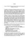
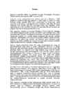
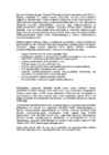


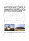


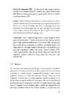


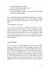
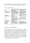
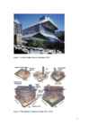
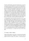
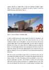
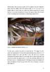


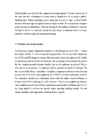
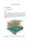

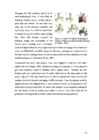
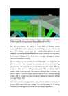

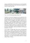
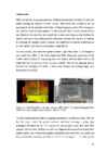
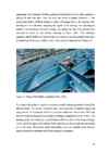

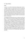

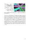
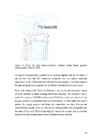
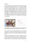
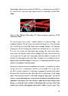

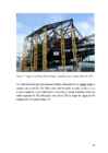
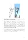
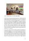


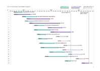
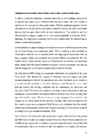
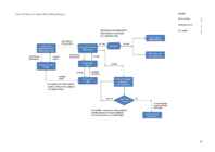
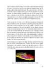
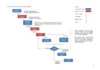


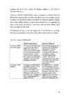
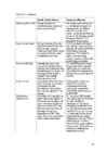
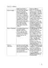


Kõik kommentaarid