Ergo Pikas
Integration of
Lean Construction and
Building Information Modelling DISSERTATION
Tallinn 2010 2
UNIVERSITY OF APPLIED
SCIENCESAuthor : Ergo Pikas-
Civil Engineering student , Faculty of
Construction , Tallinn University of Applied Sciences
Supervisor:
Rafael Sacks- Associate
Professor , Faculty of Civil and Env. Engineering, Technion Israel Institute of
Technology Consultant:
Roode Liias- Professor and
Dean , Faculty of Civil Engineering, Tallinn University of Technology
Title: Integration of Lean Construction and Building Information Modelling
Archived: University of Applied Sciences, Faculty of Construction
ABSTRACTThis research can be
divided into two. The
first part investigates the
current state of the construction
industry,
while the second part
looks at new
emerging business models in
particular , Lean
Construction (LC) and Building Information Modelling (BIM), as well as an integration of
these two.
Given that the construction industry does not have a
particularly good reputation
among the public, the
first part of this thesis focuses mainly on this problem and its
sources . It is the
reason why we need
new and better business models, like LC and BIM, or
even an integration of the two models.
Both LC and BIM have been shown to have a
profound impact on improving construction
processes and
therefore ,
project outcomes, as discussed in the third and the
fourth chapters.
Different studies and
practical experience show that a combination of these originally independent approaches can ensure
even better processes.
Integrated Project
Delivery (IPD), which is discussed in the fifth
chapter , is an
example of this. In
conclusion , a recommendation supported by research is made for improving the
Estonian construction industrys
performance .
Key
words : Lean Construction (LC), Building Information Modelling (BIM), Integrated Project
Delivery (IPD), Design-
Build (DB), Design-Bid-Build (DBB), etc. (see also 1.4).
3 TABLE OF CONTENTS
ABSTRACT .............................................................................................................................................3
CHAPTER 1-
INTRODUCTION ..........................................................................................................7
1.1 PROBLEM FORMULATION ..................................................................................................................7 1.2 RESEARCH METHODOLOGY ...............................................................................................................8 1.3 RESEARCH STRUCTURE .....................................................................................................................9 1.4 ABBREVIATIONS ...............................................................................................................................9
CHAPTER 2- PROBLEMS IN THE CONSTRUCTION INDUSTRY ...........................................10
2.1 PROBLEMS ......................................................................................................................................10 2.2
CAUSES OF THE PROBLEMS .............................................................................................................12 2.2.1 Structural: contractual systems ...............................................................................................12 2.2.2
Management in construction ...................................................................................................15 2.2.21 Conventional
production management theory in construction..........................................16 2.2.22 Conventional project management theory in construction ................................................17 2.2.23
Learning and improvement ...............................................................................................19 2.2.3
Lack of
technological exploitation ..........................................................................................19 2.3 EMPIRICAL STUDIES: SUMMARY OF RESEARCH CONDUCTED AMONG THE MAIN CONTRACTING
COMPANIES IN ESTONIA ........................................................................................................................20
2.3.1 Research summary ..................................................................................................................21 2.4 CONCLUSION ..................................................................................................................................24
CHAPTER 3- LEAN CONSTRUCTION ...........................................................................................26
3.1
REQUIREMENTS FOR A PRODUCTION SYSTEM ..................................................................................27 3.2 THE
TOYOTA PRODUCTION SYSTEM (TPS) .....................................................................................30 3.3
PHILOSOPHY OF LEAN CONSTRUCTION ...........................................................................................34 3.3.1 TFV
views as the foundation for Lean Construction ..............................................................35 3.3.11
Value in construction
projects ...........................................................................................36 3.3.12 Flow in construction ..........................................................................................................38
4 3.3.13
Waste identification in construction ..................................................................................40 3.3.2 The Lean Construction principles driven by the TFV model .................................................42 3.3.3 Management theory in construction........................................................................................44 3.3.31 Predictability in flow and processes (LPSTM) ...................................................................45 3.3.311 Levels of the Last Planner System ..............................................................................46 3.3.4 Discussion ...............................................................................................................................49 3.4 CONCLUSION ..................................................................................................................................49
CHAPTER 4- BUILDING INFORMATION MODELLING ...........................................................50
4.1
DEFINITION OF BIM: PARAMETRIC MODELLING ..............................................................................50 4.1.1 What BIM is not......................................................................................................................51 4.2 INTEROPERABILITY .........................................................................................................................51 4.3 IMPLEMENTATION OF BIM ..............................................................................................................52 4.3.11 Collaboration.........................................................................................................................52 4.3.12
Planning use of BIM .............................................................................................................53 4.3.13 BIM functionalities/uses .......................................................................................................55 4.4 CONCLUSION ..................................................................................................................................58
CHAPTER 5- INTEGRATION OF LEAN CONSTRUCTION AND BUILDING
INFORMATION MODELLING .........................................................................................................59
5.1 THEORETICAL
WORK OF INTEGRATING LEAN CONSTRUCTION AND BUILDING INFORMATION MODELLING ..........................................................................................................................................59 5.2. INTEGRATED PROJECT DELIVERY (IPD) ........................................................................................60 5.2.1 Definition of IPD ....................................................................................................................61 5.2.2Principles of IPD ......................................................................................................................62 5.2.3 Organization,
operating system and commercial
terms ..........................................................64 5.2.31 Project organization...........................................................................................................64 5.2.32 Operating system ...............................................................................................................66 5.2.33 Commercial terms .............................................................................................................68 5.2.4
Legal relationships ..................................................................................................................68 5.2.5 Discussion ...............................................................................................................................69 5.3 EMPIRICAL
EVIDENCE FOR LC AND BIM SYNERGY.........................................................................69
5 5.3.1 Crusell
Bridge case study ........................................................................................................69 5.3.2 Discussion ...............................................................................................................................71 5.4 CONCLUSION ..................................................................................................................................73
CHAPTER 6- CONCLUSION .............................................................................................................74
6.1 ANSWERS TO
QUESTIONS ................................................................................................................74 6.3
SOLUTION FOR ESTONIAN CONSTRUCTION INDUSTRY .....................................................................77 6.4 ACKNOWLEDGMENT .......................................................................................................................77 6.5 SUMMARY IN ESTONIAN .................................................................................................................78 6.6 BIBLIOGRAPHY ...............................................................................................................................93
APPENDIX 1: CRUSELL BRIDGE CASE STUDY .........................................................................97
6 CHAPTER 1- INTRODUCTION
Over time the
Architecture , Engineering, and Construction (AEC) industry has become more
complex and
demanding . Clients are no longer expecting only to meet
schedule ,
cost and
quality objectives but
also to guarantee
safety , human satisfaction and
minimal negative environmental impact (Vanegas,
DuBose and Pearce 1996).
Traditional construction project delivery methods and models have failed to
satisfy the
expectations of both contractors and clients. The main problems and their causes are
analysed in the second chapter of this thesis. Thus people in the AEC industry,
including scholars and
practitioners, have
come together to
find new
solutions for delivering projects and fulfilling high
requirements.
1.1 Problem formulation
The construction industry
makes up a great
share of the Gross Domestic Product (GDP) in many
countries all over the world and provides
employment to a great number of people. Thus, it is
important to conduct research in this
field , with a view to
making it more productive,
safe and free of
waste. This can all
happen only with a better
understanding of the concepts, principles and
physics of
the construction industry. Therefore, many
academics , academic
institutions and even companies have
started to work together to propose solutions for the problems occurring in the construction industry.
LC and BIM are fundamentally different approaches and ordinarily implemented independently. Their
great
positive impact on the industry in general has been noted by a variety of
parties .
Moreover ,
there are also significant
attempts to combine these two models to achieve even better project outcomes, as
in the case of IPD.
7 For the Estonian construction industry these are fairly new models. Thus the
following questions
drive the
present research in its
goal of gaining a better understanding of these new business models:
1. What are the main problems connected with the construction industry and what are their causes? 2. Which problems have been arising in the Estonian construction industry? 3. What is LC: the
concept , its principles and
tools ? 4. What is BIM: the concept, the
process and its functionalities? 5. Can LC and BIM be integrated and what are the
results ? 6. What is IPD? 7. Are LC and BIM
applicable to the Estonian construction industry?
1.2 Research methodology
At the
highest level, the present research can be divided into the following two
functions :
literature review and empirical study.
Literature review. This is
based on
available publications,
articles and white papers from the
International Group for Lean Construction, etc. (see also Bibliography).
Empirical study. This is based on the following three sources: first, the Crusell Bridge 1case study
(
included in the appendices), which
provided examples ; second, research
whose objective was to
determine the current state of the Estonian construction industry (see also chapter 2); and
finally ,
information gathered from visiting Estonian and Finish construction companies and discussions with
different parties from Estonia,
Finland and
England .
1 The Author of this thesis in collaboration with his supervisor Sacks R. conducted an empirical field study and
prepared the Crusell Bridge
cases study as a part of the second edition of the BIM
Handbook (see also appendix 1.).
8 1.3 Research structure
Chapter 2 investigates the main problems connected with the construction industry
worldwide and the
causes of these problems. In particular, it is investigated if these problems
apply to the Estonian
construction industry using a summary of the research compiled by the author of this thesis.
Chapter 3 investigates LC, its concept, principles and the tools that make it possible to address the
problems raised in the second chapter.
Chapter 4 discusses what BIM is and what is needed for its implementation.
Chapter 5 investigates the question of whether a synergy exists
between these two models analysed in
the second and third chapter and the question of what form it would take. Afterwards, one particular
example of the integration of LC and BIM, the IPD model, is discussed. This is supported by the
Crusell Bridge case study and a discussion of the
authors ideas .
Chapter 6, conclusions are drawn and the questions outlined in chapter 1 are answered.
1.4 Abbreviations
4D- 3D CAD + time IPD- Integrated Project Delivery
5D- 4D CAD +
money LC- Lean Construction
AEC- Architecture, Engineering, Construction
LPDS - Lean Project Delivery System
BIM- Building Information Modelling LPS- Last Planner System
CII- Construction Industry Institute NVA- Non-Value
Adding CPM-
Critical -Path
Method NVAR- Non-Value Adding
activities but
Required DB- Design-Build PPC-
Percent Plan Completed
DBB- Design-Bid-Build TFV- Transformation-Flow-Value
EstGLC- Estonian Group for Lean Construction TPS- Toyota Production System
GC- General Contractor VDC-
Virtual Design & Construction
IGLC- International Group for Lean Construction 5Whys-
Root causes analysing technique
9 CHAPTER 2- PROBLEMS IN THE CONSTRUCTION INDUSTRY
In the second chapter of this thesis, the main problems and their causes are discussed. It is
done by
analysing the literature,
previous research in this field, and the results of empirical research conducted
among the main contracting companies in Estonia. Basically, the aim is to
understand the
reasons for
the failures at the root level.
2.1 Problems
Many studies of the problems and causes for the problems mostly point out the
same issues associated
with construction industry. The
nature of the construction industry is very often characterized as the
following (Koskela2 1992):
Low productivity
Poor safety Inferior
working conditions Insufficient quality
The construction industry is
seen as an unproductive production system if compared with
other industries, e.g., car
manufacturing (Koskela and Vrijhoef 2001; Winch 1998). High levels of waste and
unpredictability in terms of delivery, time,
budget , profitability and standards of quality combine to
2 Professor, School of the
Built Environment, University of Salford, Salford, UK. One of the founders of IGLC.
Suggested TFV theory in 2000 as his PhD thesies.
10 give the construction industry one of the worst public images among the
industrial sectors (
Egan 1998;
Koskela 2000;
Santos 1999).
The
Centre for Integrated Facility Engineering, headed by Paul Teicholz at
Stanford University,
conducted research on
labour productivity in the construction industry. The productivity of the
construction industry in the US was studied in
comparison with all non-
farm industries over a
period of
forty years , from 1964 to 2003, as shown in the following
figure .
Figure 1.1 Labour productivity index for US construction industry and all non-farm industries from 1964
through 2003, source Teicholz 2003.
Figure 1.1
shows that the construction industrys productivity has declined over the last
four decades,
while the productivity of non-farm industries has more
than doubled . This
means that more work per
one
dollar needs to be carried out in 2004 than needed to be carried out in 1960 to achieve the same
results. The problem of stagnant productivity has been seen to be associated with the
slow adoption of
new and
improved business
practices and technologies.
Construction has also been seen as a wasteful process. The Construction Industry Institute (CII) in co-
operation with the Lean Construction Institute (2004) have estimated that there is up to 57% of non-
value adding (NVA) effort or waste in our current business models, but in manufacturing the
percentage is only 12%. Waste (in
Japanese "
Muda ") is an
activity that absorbs resources but adds no
11 value. The
cause of this is seen to be
related to poor
organizational management: the design of the
production system,
communication and
cooperation , and production planning and
control .
Another study performed by the National Institute of Standards and Technology
found that inefficient
interoperability between different parties and systems often prevents
members of the project
team from
sharing information rapidly and accurately (Gallaher 2004). Thus, the lack of accurate information and
its slow
exchange is one of the main reasons for the construction industrys low productivity, while
availability of information is critical in the project-based construction industry for
decision making.
In conclusion, we can say that there are plenty of problems, and therefore, it is
necessary to study the
causes of inefficiencies and to determine which of these causes has the
greatest negative impact on
performance.
2.2 Causes of the problems
Many causes for the problems start from
client due to reason that client is not a professional. Too
much
attention is put on
price than quality; i.e. contractors (all different specialty contractors) are
chosen by the lowest bid. Also poor
briefing and definition of the requirements for the project needs
and functionalities
result in the
late changes of the design. It is due to the lack of systematic
understanding of construction projects. Not only but also contractors unprofessionalism and
incompetent commitment to the project are also issues that cause many problems.
2.2.1 Structural: contractual systems
Over time,
facilities have become more complex, demanding and variable, resulting in the need to use
specialty contractors, now accepted
practice . Thus, to
manage project-based construction processes,
the two most prevalent contracting systems, Design-Build (DB) and Design-Bid-Build (DBB), were
developed (see also figure 2.2).
12 Figure 2.2 DBB and DB model, source Guyer 2005.
Of
course , there are more
ways to structure the project delivery process but the
ones mentioned
above are most commonly used. Each has its own advantages and
disadvantages , but in general, the main
problem connected with these two models is that they divide the project delivery process into
fragmented stages, where a sense of the
whole is
lost . Thus it is very often the case that a designer
develops a product that is very complicated and
expensive to construct. Inconsistency, inaccuracy, and
uncertainty in design make it difficult to fabricate materials offsite, and the
fact is that most
construction work must be carried out on site, where working conditions are more unpredictable than
in a factory. Working on site instead of in a factory is conducive to ineffective work, resulting in
rework, working slowly and inventing work, thus
leading to cost and time overruns. It creates the
brick wall effect : the results of preceding stages will be thrown over the wall into the
hands of
other project
parties, and this causes a loss of information and competence.
However , the flow of accurate
information in project-based delivery systems (the construction industry) is
crucial for successful
project outcomes.
In general (this applies to both contracting approaches), if a contractor has made a bid under the actual
estimated price, what frequently happens is that the contractor abuses the
change process, relying on
error- and omission-ridden design documentation. For example, the contractor uses
cheaper and
lower quality materials, which very often leads to
friction and disputes between the
owner and the project
team.
13 In the first chapter of the "BIM Handbook" (Eastman, Teicholz, Sacks, Liston 2008), the authors
gave a critical
assessment of existing DB and DBB contractual models and finally proposed the kind of
model which would
best support the implementation of BIM.
The two
major benefits of the DBB model are
competitive bidding to achieve the lowest possible price
and less
political pressure when selecting a given contractor, while the benefits of using DB are the
fact that the responsibility for design and construction is consolidated into a
single contracting entity
and the simplification of the administration of tasks for the owner (
Beard et al. 2005). These benefits
aside, there are disadvantages connected with DBB and DB as well, as shown in the figure
below .
Design-Build
versus Design-Bid-Build: Advantages and disadvantages Advantages Disadvantages Design-Build (stipulated price) Building is fully defined Limited assurance of quality control
Agency may
avoid disputes and conflicts Subjective contract award
Builder involved in design process Limited
access for small contractors Faster project delivery Agency needs less
stuffDesign-Bid-Build Building is fully defined Agency
gets involved in conflicts and disputes Competitive bidding results in lower price Builder not involved in design phase Relative
ease assuring the quality control Price not certain
until construction price is
received Objective contract award Agency may need more technical stuff Good access for small contractors
Table 2.1 Advantages and disadvantages of DBB and DB model, source Guyer 2005.
In the DBB model, the client has separate contracts with the designer and general contractor (GC).
Traditionally, the client also has a different contract with technical consultancy, whose work is to
represent the client on site in
matters related to different technical/technological issues. Contractors are
usually chosen by the lowest bid, tempting
them to optimize their activities by reducing the resources
needed to
deliver the project; consequently, this often leads to sub-optimal results. As GC's are chosen
by the lowest bid, they use the
Dutch auction to
select sub-contractors, and this in
turn encourages sub-
14 contractors to rig and
cover their
costs and
reduce resources being
spent on a project. Bids are
quite frequently under the actual estimated price, and so understandably, it is in the
interest of contractors to
optimize activities they execute to
stay within a limited budget. This, of course, is the opposite of what
the client is expecting. This leads to conflicts, errors, and omissions in the project documentation,
which in turn leads to waste of time (idled labour,
equipment , etc.) and money in the construction
phase.
According to the DB model, the client directly contracts with the DB team to
develop a well-defined
building
program and a schematic design. After that, the DB team estimates the
total cost and time
needed to
carry out the construction work. The good
thing with this model is that modifications can be
made in the
early phase of design, reducing the money and time spent on doing it. After the cost and
time required are settled on by the client and DB contractor, from this point on, the contractor basically
gets
full control over the project,
giving the client less flexibility. For the client this results in limited
assurance of quality control and limited access to sub-contractors.
2.2.2 Management in construction
Production management in construction, according to the present view, is divided into two main
theories: production theory and management theory. In LC, production theory
consists of three
different sub-theories. This is the Transformation-Flow-Value (TFV) model defined by Koskela
(2000), where the sub-theories are integrated together in
purpose to accomplish a comprehensive
theory of production (see chapter 2). Traditional management only focuses on the transformation view,
as
described below. At the same time, management theory consists of sub-concepts for ,,planning,
,,execution and ,,control of a production system. Koskela and Howell (2004)
argue that the practice of
construction management suffers from the three following shortcomings:
The
role of planning is not logically defined, and short-
term planning is normally poorly carried out or simply neglected. Execution is not
managed efficiently. In other words,
action is taken on tasks pushed by the plan
without considering
real conditions, as
higher level
plans are
translated into short-term plans and then into action.
15 Control is too narrowly seen as measuring and
taking corrective action,
rather than as a process of learning.
Probably, decades ago, these traditional theories adequately satisfied requirements for the delivery of
projects, but as society rapidly developed and over time,
along with the construction industry
became more complex and
dynamic , the time arrived for a more comprehensive theory. LC is seen as one
option for tackling these vast developments and changes, while it
offers a coherent philosophy
behind principles and methodologies.
2.2.21 Conventional production management theory in construction
The conventional production system in construction is based on the "Transformation" concept of
production, and it has dominated most of the
20th century . Basically, a production system in
construction should meet the three following
criteria (Koskela and Ballard 2003): delivery of the
product, minimizing of waste, and maximizing of value. The current view only satisfies the first one
delivery of the product. This model views production as the transformation of inputs into outputs
(conversion activity), where an economically efficient process is achieved by improving each
task independently, at the same time neglecting organizational management. A project is usually divided
into smaller manageable chunks (e.g., tasks/activities) by using the work breakdown structuring
method, which afterwards can be measured and analysed for planning. For each sub-process, the
required resources are allocated without considering the current
status of the production system; i.e.,
production is only
focused on value adding activities (VAA) (see also chapter 3). As a lot of research
has shown, this does not
lead to more productive production. It is not the point
speed that is important
but rather the general throughput. The next figure illustrates the general
idea of the transformation
model:
16 Figure 1.3
Basic idea of conventional management, source Koskela 2000.
Many researchers point out the lack of a
specific theory for construction. At the same time, a bad
implementation of the few existing theories has been the root cause of construction industry
underperformance and insufficiency (Koskela & Howell, 2002). Consequently, an explicit theory is the
crucial and single most important
issue for the future of the project management profession (Koskela
and Howell 2002). Production in construction can and should be seen as a flow (Santos 1999).
2.2.22 Conventional project management theory in construction
Conventional project management tries to manage projects by scheduling (mainly by
applying the
critical-path method (CPM)), cost, and output. The CPM method was developed by DuPONT and
Remington Rand
around 1957. It was developed to mathematically calculate the sequence of activities
in
order to
complete a project within the minimum time possible. CPM programs show activity
dependencies and duration allocated for each activity. It also allows calculating the float of an activity,
where float is the
amount of time for how long a non-critical activity can be delayed without affecting
the
overall program.
Today , the
majority of construction companies use CPM as the main project
management, planning and
controlling mechanism, and it has been the main method over the last 4-5
decades. The main problem with CPM is that it does not
consider other prerequisites
beyond the
preceding task, and it pushes work on instead of pulling work to completion. Of course, there are also
other existing management methods, for example, line of
balance , which was originally developed by
the Goodyear Co. in the early 1940s and was
further developed by the US Navy in the early 1950's for
programming and control of both
repetitive and non-repetitive projects (Turban 1968;
Lutz and Halpin
1992).
Here we
focus on CPM because it is the most common method used in Estonia and other
countries as well.
17 Management is primarily focused on organizational structuring and the
creation of work breakdown
structures . This leads construction into a situation where peculiarities appear, causing variability in
production operations and a dismissal of the improvement process.
Scheduling means that activities are put into
logical sequence to understand when each task should
start, and the work of managers is to start the tasks as early as possible, in many cases leading to
overproduction (a type of waste see also chapter 3), and this in turn leads to uncertainty and
unpredictability. Tasks are put under someones (a sub-contractors) responsibility
through contracts.
But breaking down activities into smaller ones, the basic idea of conventional management, makes the
links between tasks weaker. The
release of
works form one
crew to another one is assumed, and the
result is an even more unpredictable workflow.
Of course, we can not
claim that the conventionally accepted philosophy is not trying to deliver the
value generated
during the design phase. This is definitely the aim at the
beginning of the project, but
very often it is not achievable using existing management techniques, which
push for early
decisions and
local optimization. The sources of that are usually risks that are shifted onto sub-contractors
through contractual obligations, and the
goals of the main contractor goals are unclear. So they are
attempting to optimize their activities, and this leads to sub-optimal outcomes for the project, and these
usually do not
agree with general project goals. This is the opposite of what the main contractor
managers are trying to achieve, namely, the best value and results for the customer.
Control operation, based on thermostat theory, is to
monitor if a project is within cost and time
limits .
Action is taken only when delays in work appear. The techniques used to
improve the situation often
consist of speeding up sub-contractors, bringing in additional
workers or re-sequencing
jobs so that
more important ones are
finished first. Thus, managers are
busy fixing the tasks that were not
delivered on time, and this leaves them less time for planning upcoming tasks. This leads to the following
project results: low productivity, poor safety, inferior working conditions, and insufficient quality.
Winch has
stated the following causes for poor project management more succinctly, but they are
basically the same as discussed above:
18 Table 2.2 The causes of problems in managing construction projects, source Winch 2009.
2.2.23 Learning and improvement
As a project-based environment, construction project delivery is a complex and dynamic process
which makes
continuous learning critical to the improvement of processes and therefore to the
successful delivery of the project within time and budget limits. Conventional management techniques
and processes lack the metrics that help to
measure the productivity of construction work and fail to
understand the causes of the failures. Last Planner System (LPS),
invented by Ballard and Howell in
1992, adds a control
component , Percent Plan Completed (PPC), to the traditional project management
system to measure productivity. It is about learning from your own failures on a weekly or even
daily basis and by doing it you can improve your production system (see also chapter 3).
2.2.3 Lack of technological exploitation
Implementing new technologies in the construction industry is seen as one possibility to improve the
construction industrys productivity. Other industry sectors have
already done it and adopted many
new technological innovations, and because of this they have witnessed a great
rise in efficiency and
productivity. This is probably due to the peculiarities of the construction industry: one-of-a-kind
19 projects (basically the production of prototypes); site production (production
units move through the
product, unlike the case in manufacturing, where the product moves through
assembly units on the
shop floor); and temporary organization. But these peculiarities can be mitigated or eliminated
altogether.
One of the main problems connected with the construction industry is that
paper -based (2D) drawings
are used for information exchange and constructing. Paper-based modes are
prone to errors and
omissions due to the reason that the drawings are created by
hand and by many different parties. This
often causes unanticipated field costs, delays, frictions, and eventual lawsuits between the different
parties involved. A common problem associated with 2D paper-based documentation is that
considerable time is needed to
generate critical assessment of a proposed design in terms of cost,
energy-efficiency, structures, etc. Often, these analyses are carried out at the last
minute during the
design process or even in the construction phase, when making changes is more expensive.
BIM (see also chapter 4) is seen as one solution for improvement. In recent years, more and more,
companies have started to use applications that support the BIM model in
place of applications that are
based on 2D. Using BIM enhances the need for collaborative team work, speeds-up information
exchange, and makes it more transparent and accurate.
Still , it must be
understood that BIM is
effective only when implemented properly. Doing it the
wrong way can result in
greater waste
(implementing BIM demands a great amount of initial funding) than is currently the case in the
construction industry.
2.3 Empirical studies: Summary of research conducted among the main
contracting companies in Estonia
The non-
profit organization Estonian Group for Lean Construction (EstGLC 3),
established May 20,
2009, and the author of this thesis conducted research among the 11
biggest Estonian GCs to
determine the principle problems, their causes, and their
consequences . For this study, the author of
this thesis created an interactive
survey in a web-based environment at the following address:
3 Estonian Group for Lean Construction (EstGLC) establised 20. May of 2009,
member of IGLC and European
Group for Lean Construction, further information: www.etet.ee
20
http://www.survsoft.com/esurv.php?s=26518&k=11074-0-25885 . Approximately 150 people were
questioned and we received 78 acceptable answers. This summary is based on the following
report "Ehitusprojektijuhtimise olukord aastal 2009" compiled by Ergo Pikas and EstGLC (if interested in the
report,
please contact the author of this thesis).
2.3.1 Research summary
64,75 % out of 379 projects were private
orders , and another 35,25 % were public orders. Of these,
53,5 % were built according to the DBB contracting model, while another 38,5 % followed the DB
contracting model. The remaining 8 % were other kinds of models. Thus the DBB contractual model is
the most used model in the Estonian construction industry. It is probably due to the fact that Estonian
clients and investors pay too much attention to price rather than quality. They also
tend to fail to
consider other
fundamental values that a construction project ought to satisfy. As discussed in the
earlier subchapters, the DBB
approach is the most fragmented project delivery structure.
Consequently, all the associated problems and their causes
named in previous subchapters apply to the
construction industry in Estonia.
We tried to determine the main applications that site crew members use daily. The figure below
illustrates that site crews use mostly traditional applications that have been in use on
sites over many
decades. Thus a
failure to
exploit new information and communication tools in Estonia can also be
seen as one of the main causes of problems. It is surprising if one considers that Estonian society is
committed to being a leading edge information society. 60 % of contractors use
Microsoft Project for
daily work (scheduling tasks), while this model is based on CPM. Thus the prevailing problems
(discussed previously) related to this management method also apply to the Estonian construction
industry.
Research also revealed that Estonian site crews do not use applications that support the BIM model.
Therefore, it is possible that partial improvement in the
near future can come through involving BIM
in management for construction projects. The Crusell Bridge case study shows that improvements in
management are possible by employing BIM (see also sub-chapter 5.3.1 and appendix).
21 Figure 1.4 Most commonly used applications on site, Ergo (2009)
The
size of the site crew differs corresponding to the
complexity and cost of the project. Basically, this
means that the more expensive and complex a project is, the more team members will be involved in
temporary organization. Building a team where
trust ,
respect and synergy between each other are
present is an
essential when striving for a better project.
GC's size of site crew according to the project price 30 Size of crew
20 10 0 1-20 milj 20-50 milj 50-100 milj 100-500 milj 500-1000 milj 1000-.... milj
Figure 1.5 Site crew size according to the project budget, Ergo (2009). Milj- means in
English million.
Problems that were revealed in the first part of this chapter apply to the Estonian construction industry
as well. Answers to the question, "What are the main aspects that cause problems on site?", were
incomplete project documentation at 18 % and errors and omissions in the projects at 12 %. This is
proof that fragmented project structure causes a lot of problems at the construction stage. Contrary to
22 this, many
organizations and companies all over the world are already practicing integrated models,
where pains and gains are shared through collegial agreements. Doing so, they have reduced
expenses and time to deliver the project by up to 30 % (see also
http://www.ipd-ca.net/ ).
Table 2.4 The main problems arising during project delivery, Ergo (2009)
What idles work, labour and equipment on site were also investigated. Mainly the same options as in
previous table were given to respondents. The main problem
here is related to poor planning, at 14 %.
Current management methods (CPM, Line of Balance, Critical
Chain , etc.) are not sufficient in
satisfying all
seven prerequisites or
resource flows that must be fulfilled to execute the task (see also
sub-chapter 3.3.12). In second place, errors and omissions in a project, at 13%, also cause idleness on
site. However incorporating changes and corrections in a design during the construction stage is
frequently a complicated, time consuming activity and expensive for the owner.
23 Figure 1.6 The main problems that idle work and labour on site, Ergo (2009).
This research revealed that the causes for counterproductive and insufficient project delivery are poor
short-term planning and inadequate project documentation. The Estonian construction industry does
not
differ much from the construction industries of other countries. It has
similar problems, and this is
why it should be possible to learn from the
experiences of other countries. The author of this thesis
believes that these problems can be mitigated or eliminated by tackling the root causes, using new
business models, in this case, LC and BIM.
2.4 Conclusion
"The 6th annual survey of construction owners" by CMAA4 (2005) has stated it very succinctly: The
biggest cost impacting construction today is that of inefficiencies built into the way projects are run
and managed not costs of raw materials like
steel and concrete, or the cost of labour.
The author of this thesis argues that the current theory of construction is inadequate and is the main
cause for the construction industrys lack of productivity and insufficiency. Current theory is based on
Transformation theory, instead of TFV, as suggested by Koskela in 2000, and does not give an explicit
understanding of construction and what is needed to successfully deliver projects (see also chapter 3).
4 CMAA- Construction Management
Association of America, www: www.cmaanet.org/
24 The general idea of current management theory is that projects consist of many separate and
independent stages and activities, where
economic efficiency will be achieved by improving each of
these stages or activities independently. Thus, it neglects the systematic understanding of construction,
i.e., where all the processes and stages in project delivery are coherent and
influence each other to a
greater or lesser degree.
Such an understanding of construction has given birth to the currently existing and mostly commonly
used contractual models: DBB and DB. These tend to
fragment project delivery, resulting in the loss of
information and competence among experts at different stages. It creates the
silo effect, where experts
in different phases do their work and then throw it over the wall into the hands of other experts. Thus,
it creates the effect that experts must recover the information they got from the previous project stages.
This causes a
double handling of information, where information due to human error can be lost. If
you also consider unprofessionalism and incompetent commitment to a project, together with the fact,
as revealed by the cited research, contracting companies are not
open to new technological
innovations, then the outcomes of the project will not be as
expected by any of the parties involved.
Finally, the consequences are facilities which are not energy-efficient (70-80% of energy use is defined
during schematic design), are not constructible, have incomplete project documentation (error- and
omission-ridden), and show poor short-term planning. The last two consequences have been
statistically demonstrated by the author of this thesis. The problems and their associated causes
revealed in the literature review apply to the Estonian construction industry, as demonstrated by the
research summary, even if we take into
account a
difference in
cultural backgrounds.
25 CHAPTER 3- LEAN CONSTRUCTION
Problems and
constraints related to conventional production management, as discussed in the previous
chapter, all lead to unproductive and inefficient project delivery. As a consequence, the construction
industrys reputation among the public is not the best. At the same time, the productivity of other
industries has risen multiple
times over the last century, e.g., that of Toyota Motors Company, which
has developed its own production system,
known as Toyota Production System (TPS).
As many researchers have confirmed, the existing production system in construction lacks explicit
theory and is underperforming. A group of enthusiasts established the International Group for Lean
Construction in 1993 with the aim of bringing innovation and improvement to the construction
industry. After nearly ten years of study, Lauri Koskela recommended in his Doctoral thesis a TFV
model of production integration of three different production models. All these models existed in the
20th century separately, and each of them was
considered a different part of TFV theory, but when
integrated together, the result is a more explicit and comprehensive theory of production. We can say
that the starting point for him was TPS, but over time Lauri Koskela and other academics in this field
have pulled in various other theories. The next figure is a simplified illustration of the previous
statement :
Figure 3.1 TPS as the cornerstone for LC, adapted Lauri Koskela presentation from "First TTK Day of Project Management", 2009 November.
26 In succeeding sections, we will try to determine the requirements that a production system ought to
fulfil. After that, we take a brief
look at TPS, and this will be followed a
consideration of the TFV and
LC models. Finally,
LPS5 , one of the most
powerful tools for enhancing flow in construction, is
discussed.
3.1 Requirements for a production system
Science in the
matter of production theory has the two following goals (Koskela 2000): explanation (or
understanding) of production and
prediction of the future. Basically, what this means is that theory
should
allow us to foretell upcoming events in the system under consideration, and to understand the
interactions between units and processes. All processes in production involving human action and
organizational management are in a coherent system; understanding these
patterns is essential for
future improvements. This
requires an understanding of the metaphysical nature of
reality and with the
use of empirical studies and evaluation of their
validity . This is a
circle of science where academics
learn from reality and then try to put the
observed into theory and then apply theory
back to practice. It
is a continuous
never ending process.
Koskela claims in his research, which is based on a thorough literature study, that production theory
consists of three levels, as shown in the next figure:
Figure 3.2 Practical methodologies are based on concepts and principles, source Koskela 2000.
5 Last Planner System is a registered trade mark of the Lean Construction Institute www.leanconstruction.org.
27 The highest level of the
pyramid answers the question: "What is a production system?" It
states the
goals and requirements of a production system. Considering the TFV model proposed by Koskela, a
production system in construction should fulfil the following three goals:
delivery of the product minimization of waste maximization of value
The second level is heuristics, common ways to contribute to the production system goals and to
understand the
relations between the concepts. These are the requirements for how
methodologies/
actions /techniques must contribute to the production system goals, involving an
understanding of how actions
relate to goals. As the two
upper levels
involve the
notion of concept,
then these must be converted to reality through methods, techniques, functions and etc. (
Henrich ,
Bertelsen, Koskela, Kraemer, Rooke, and Owen, 2006).
On the most general level, there are three possible actions or functionalities in construction projects:
design of the production system, control of it in order to realize the production intended, and
improvement of the production system (Henrich, Bertelsen, Koskela, Kraemer, Rooke, and Owen,
2006). These functionalities should be understood as a coherent system, where design of the
production system must be structured as simply as possible to deliver all the expected values and make
reducing waste from the processes and operations feasible. It means design should facilitate (i.e., make
transparent) operations and improvement. Operations should
provide empirical data about the
production system to the improvement action (e.g. PPC, see subchapter 3.5.1). Finally, improvement
should address both operation and design of the system with
relevant information for improvements.
Figure 3.3 Three main actions in construction projects, source Lauri Koskelas presentation at "First TTK Day of Project Management" November 2009.
28 Simply said, a production system in construction should be built up in a way that it gives decision-
makers (managers) the information needed: the level of resource utilization, and controllable
elements /parameters (metrics). It means a production system should
supply managers with elements to
manage work in matters of quality, speed, dependability, flexibility and cost. This is needed to deliver
work on time and to ensure minimal work in progress, short customer lead times, and
maximum utilization of resources. However, in-depth analyses of these goals show that they are in conflict. For
example, it is easier to finish work on time if resource utilization is low. Thus, it is necessary to
balance these goals.
It is definitely not as
simple as it sounds. Because construction is a dynamic and complex system, its
peculiarities make it difficult to design a production system in a simple way. According to Koskela and
Ballard (2003), these peculiarities cause high variability. Therefore, peculiarities must be eliminated or
mitigated first hand (see table 3.1 below).
Peculiarity Problems Solution
One-of-a-kind production
Almost every project is as a Pre-engineered delivering prototype
products ; integration of different phases
Site production External uncertainties; task Use prefabricated elements interdependencies
Temporary organization Optimization of activities Long-term alliances; team (lowest bid); unreliable building from the exchange of information
really point of beginning Table 3.1 Peculiarities of construction, source Koskela & Ballard 2003.
Now that we have outlined the requirements that a production system ought to satisfy, we can go
forward with the TPS system, which is
briefly discussed to make it
clear why it has been so successful
over the last decades. After that follows a discussion of TFV and LC.
29 3.2 The Toyota Production System (TPS)
TPS or just Lean manufacturing is a management philosophy for how to organize and manage the
production processes. TPS was developed by the Japanese car manufacturer Toyota between 1948 and
1975. It was created by a group of engineers led by Taiichi Ohno6. He was a
smart though difficult
person dedicated to eliminating waste.
As the situation after WW II was economically complicated, Ohno understood that it was essential to
treat a production system as a whole and to make it flexible. He
took over
Henry Fords work and
continued to develop flow-based production management according to his own understanding. The
result was one-
piece flows. He also understood that the scheduling of work should not be driven by
sales and production targets, but by actual sales. This created the need for "
pull " system.
Engineer Ohno saw waste in every
step of the conventional production system. If conventional
production management is about producing as many cars as possible in the shortest feasible time
(which is exactly the case in mass production), then Ohnos system is about making
perfect cars (by
decentralizing the decision making process, Jidoka7) in a flexible way and in the shortest time with
nothing in
inventory . It means that work stops if there are no orders from customers. The most difficult
problem involved supplying production with the necessary bulk materials. In particular, it made
planning and organizing the production system very important.
As he became
aware of waste reduction in production, he understood that decisions made in the design
phase
affect cost and the sophistication of the execution phase. Thus he started to standardize design
by considering all the limits that other stages of the production system are
setting .
Taiichi Ohno, founder of TPS, expressed it in 1988 even more succinctly (Liker, 2003): "All we are
doing is looking at the time line from the moment the customer gives us an order to the point when we
collect the
cash . And we are reducing that time line by removing the non-value-added wastes."
6 Toyotas
executive , invented Toyota Production System between 1948 and 1975.
7 Sakichi Toyoda invented the principle of "intelligent automation" or "automation with a human
touch ".
Decentralizing decision making.
30 TPS is a sophisticated system of production, where all parties concerned must contribute to the whole.
It encourages people to continually improve and learn the processes they work on and make it last in
any business, which is the real
challenge of TPS. The Toyota Way is based on
five core values that all
workers from top management down to
regular operators are expected to
follow and
live by in their
day to day work (Bicheno J. and Holweg M. 2009):
1. Challenge to
maintain a long-term
vision and strive to meet all changes with the courage and creativity needed to realize that vision. 2.
Kaizen to strive for continuous improvement. There is always
room for improvement, perfection does not
exist . 3. Genchi Genbutshu go see the problem, in other words, go to the source of problem. This is the
belief that practical experience is valued over theoretical
knowledge . You must see the problem to understand it. 4. Respect to make every effort to understand
others ,
accept responsibility and build mutual trust (introvert and extrovert). 5.
Teamwork to share opportunities for
development and maximize team and
individual performance.
Values drive the
universal principles that are
employed at every stage of production. The
principles/heuristics are the foundation of TPS,
driving the tools and
peoples behaviour daily.
31 Figure 3.4 4P8 of Toyota Way, source Liker, 2003
Fujio Cho,
President of Toyota Motors
Corporation , has said (Liker 2003): "Many good American
companies have respect for individuals, and practice kaizen and other TPS tools. But what is
important is
having all the elements together as a system. It must be practiced every day in a very
consistent
manner --not in spurts--in a concrete way on the shop floor."
The critical starting point for Lean Manufacturing is to identify the value for the
ultimate customer.
The first question in TPS is: "What does the customer want from this process?" It is about
understanding a customers expectations in the purpose of the design production system, where
maximum value is produced and waste is minimized. TPS is very much based on flow theory, which
considers conversion (VAA) and flow (NVA, like inspection,
waiting ,
moving ) activities. Conversion
activities are
bound together through flow activities. Thus flow activities must be taken under
investigation to eliminate non-essential activities or simplify and make activities which can not be
eliminated from production more efficient. Reducing the share of NVA activities is expected to
generate one or more of the following benefits (Koskela 2000):
Lead time compression
8 4P is Likers provided set of Toyotas principles.
32 Variability reduction Simplification
Increase of
transparency Increase of flexibility
Conversion activities that conventional managerial principles take under consideration must also be
made more efficient, according to the lean production philosophy.
Figure 3.5 Production as a flow process: simplified illustration. The shaded boxes represent NVA, in
contrast to VAA, source Lauri Koskela 1992.
Under conventional managerial principles, flow activities are not being taken under control and
improved. That has led to uncertainty and cost expansion of non-value adding activities. That is why
material and information flows are taken under consideration during
analysis in the new production
philosophy. Flows are characterized by time, cost and value. Flow is the foundation of Toyotas
success . Single-piece flow gives flexibility to TPS, which is essential to
endure in the rapidly
changing car
market . All this demands a complete rearrangement of your
mental furniture. Doing things the
wrong way leads to the creation of "Muda". It is better when you focus on the product and its
requirements, rather than the organization and the equipment, so all the activities needed to design,
order and provide a product
occur in a continuous flow.
Ohno had a vision. He took all the different production theories under consideration, the most
important one being Henry Fords idea of mass production. He understood that Fords production
system wasnt applicable to the Japanese market because its demands were many times lower. He
understood that he had to be flexible and start by redesigning the production system. He spent
hours and
days on the shop floor in a
chalk circle investigating the
location of hidden "Muda". He took
dramatic steps and redesigned the whole production system by employing Just-In-time (JIT), Jidoka
33 and many other principles and techniques. It was the beginning of TPS, now considered to be one of
the best production systems in the world. It is important to see the world from another angle and to be
ready to think out of the "box", to be ready to consider alternatives and be brave enough to try to
employ them. Changing the way people think is important, and it can only happen if they are
continuously
trained and coached to see the world in a different way.
3.3 Philosophy of Lean Construction
Project-based management is made up of three
sides of a triangle (see figure 3.6): organization,
commercial terms and operating system. The LC approach starts by redesigning the production system,
by implementing many different principles, techniques and tools, many of them adopted from Toyota
to make workflow more predictable. Predictability gives
freedom and creates new possibilities. When
flow is made predictable by reducing
variation , the following things will
begin to happen: total system
performance improvement, simplified coordination and the revelation of new opportunities for
improvement.
Figure 3.6 Project-based management: three sides of a triangle, source Karlsruhe EGLC conference November 2009.
Management in construction consists of two different theories: production theory and project
management theory. Production theory in LC is based on the TFV model, which is a foundation for
how production in construction should be structured to facilitate operations and improvements
(continuous learning).
34 3.3.1 TFV views as the foundation for Lean Construction
TFV theory is an integration of three different concepts of production. These concepts individually
consider different parts of production; i.e., separately they do not cover all production processes and
operations. Isolated employment of these concepts frequently results in low productivity and all the
problems discussed in chapter 2. Koskela (2000) summarized the views of production according to
each of these TFV concepts in table 3.1 below:
Table 3.1 Integrated view of production, source Koskela 2000.
When investigating these different concepts separately, it is
easy to understand that they are partial. If
integrated together, it would give us a more comprehensive theory of production. The main principles
and sub-principles associated with these three different views of production are summarized below in
table 3.2:
35 Table 3.2 Main and sub-principles of production, source Koskela 2000.
These principles gathered together in table 3.2 were the foundation or
reference point for Koskela
when he
formulated the main goal of LC, which is following:
"Lean construction is a way to design production systems to minimize waste of materials, time,
and effort in order to generate the maximum possible amount of value"
The goal of LC is to drive the process according to principles and
explain what kind of interactions and
activities are expected to achieve the best results.
3.3.11 Value in construction projects
The starting point for Toyota is the client/customer and the first question is always: "What does the
customer want from this process?" Doing
something else other than what the customer expects is
always waste. Therefore, understanding the value for the customer should be as critical as it is in TPS.
A clear and thorough client briefing is considered to be the most useful
strategy for reducing variations
(AlSehaimi and Koskela, 2008).
Studying and understanding the value parameters and
purposes of the
client is a bilateral communication between the
supplier and the customer, as illustrated in the
following figure:
36 Figure 3.7 The conceptual scheme of a supplier-customer
pair , source Koskela 2000,
Frequently, clients lack knowledge of construction management, and it is difficult for them to share
their ideas. It means a client must be taught through multiple
negotiations and study sessions to
determine his/her value parameters and main objectives. In conventional management, investigation of
value parameters was an issue only for the client and consultant, i.e., the experiences and knowledge of
general contractors, the main suppliers, etc. were
left out of the value generating process. Very often,
the result is a design which is not constructible but consists of errors and omissions. LC enthusiasts
recommend using integrated work groups, where not only the client and consultant are present, but
also the general contractor and main suppliers, to use their experiences and knowledge as well. Their
first aim is to confirm that the
designed product is constructible; however, often they also bring
innovation to the value generating process. Designers and contractors must understand that the
primary object of the design process is to minimize building life
cycle costs
direct and
indirect related to
energy use,
maintenance , waste disposal, and occupant health and productivity, to minimize
environmental impacts
throughout the building life cycle, including product manufacturing,
construction, use/occupancy, and renovation/reuse or demolition, and to optimize indoor
environmental quality. This can only happen through
intensive design in the early phase of project
delivery, where alternatives should be explored and analysed to
choose a best solution. Emphasizing
intensive design by using BIM supported applications has been seen to be very adequate. The use of
virtual models makes information exchange and communication transparent and clear. It helps the
client and other parties involved in the project, directly or indirectly, to work on the same page.
Basically, it all means that decisions made in earlier phases in the project delivery have a greater
impact on results, and these decisions facilitate all the following stages of project delivery. All the
values that were
discovered in the feasibility phase and design facilitate construction by
providing the
information required to design the production system, organize operations, and couple these with
37 learning, resulting in performance improvements. The loss of value must be minimized by reducing
and mitigating the peculiarities of construction that cause a high level of unpredictability.
3.3.12 Flow in construction
It is
claimed in different research, articles and literature that the flexible single-piece flow, including
accurate in-flows (resources feeding the transformation), is the key to Toyotas success. However,
current construction production management tends to neglect the flow concept.
Establishing construction production system flow should be the starting point for (re)designing the
production system. Construction processes must be seen as a
network of transformation activities and
operations, where the human
factor is not of less
importance . Koskela (2000) defines production in
construction as being of the assembly-type; i.e., material flows are aggregated until they generate the
end product. However, seeing construction as a form of manufacturing sounds quite complicated,
while construction has its peculiarities.
Transformation and Flow concepts of production more or less overlap. Conversion activities are bound
together through flow activities. These flow activities must be taken under investigation to eliminate
unnecessary activities and simplify and make more efficient those activities that can not be eliminated
from production (see also sub-chapter 3.2). Conversion activities must be also addressed and made
more efficient.
Koskela (2000) points out that site construction has three general material flows (which have seven
sub-flows, or prerequisites), while manufacturing has only two.
38 Table 3.3 Material flows in car production and site construction. The
seat and
window components are used for illustration. The concept of task is presented for comparison, source Koskela 2000.
These three are general flows on site which are divided into seven prerequisites to make the task
sound , as shown in figure 3.8; i.e., all resources must be present to complete the task.
Figure 3.8 Comparison of a task-based construction process view and flow-based construction process
view, source Koskela 2000.
The figure on the left represents the traditional construction process view (tasks are pushed on sub-
contractors according to CPM) and the figure on the right represents the flow view of construction
(considers current status of production, short-term planning LPS). According to the new view, the
execution of a task will start when all the prerequisites have been completed. Failure of just one of
these usually leads to a making-do kind of waste (Koskela 2004). When managers are trying to avoid
the idleness of their crew, equipment, etc., without
thinking of consequences, they realize that work
with one or more prerequisites
missing . This generally has an impact opposite to that expected; i.e., an
39 increase of process time and variability, as well as a
decrease in
worker motivation due to the fact that
workers must
invent work for themselves.
Ballard9 (2002) also presented a general three flow model, based on the nature of the flows:
Directives Prerequisite work Resources
"Directives provide guidance according to which output is to be produced or assessed. Examples are
assignments , design criteria, and specifications. Prerequisite work is the substrate on which work is
done or to which work is added. Examples
include materials, whether ,,raw or work-in-process,
information that is input to a calculation or decision, etc. Resources are either labour,
instruments of
labour, or conditions in which labour is exercised. Resources can
bear load and have finite capacities.
Consequently, labour, tools, equipment, and
space are resources." (Ballard G,. Tommelein I., Koskela
L., and Howell G. 2002)
Koskela and Ballard might have a slightly different understanding of flows, but the aim is the same
reduced variability in these flows is a key to better projects.
Glenn Ballard and
Gregory Howell noted
in their research in the early 90s that only 54 % of planned tasks are completed weekly. Thus, they
developed LPS in 1992 to increase the
reliability of planning as a mechanism for improving project
performance (see sub-chapter 3.5.1).
3.3.13 Waste identification in construction
To create a flexible process (smooth and balanced flow) which also
takes into account the current
production status, then it is necessary to understand which activities do not create value, but only waste
(in Japanese "Muda") and eliminate or mitigate them.
9 Glenn Ballard is a
founding member of IGLC, a construction industry consultant, and a Lecturer in the
Construction Engineering & Management Program,
Department of Civil & Environmental Engineering, University
of
California at
Berkeley .
40 In general, there are various levels of waste in construction projects, but here it is mostly focused on
waste generated during the execution phase. Conventional management is task-oriented management
and by its nature, neglects the idea of flow in construction, and basically this is what causes problems.
The primary goal of LC is to avoid waste. Koskela (1992) identified the following 7 wastes in his
report, following Ohnos waste identification system. In 2004, Koskela also added one more waste as
the eighth kind of waste in construction, making-do; i.e. starting a process in sub-optimal conditions
(see also previous chapter).
1. Quality costs 2. External quality costs 3. Lacking of constructability 4. Poor material management 5.
Excess use of materials on site 6. Working time use for
none -value adding activities 7. Lack of safety 8. Making-do
According to the Construction Industry Institutes research on the topic "Lean Principles in
Construction" (2005), they identified and named three
types of activities. CII
determined that
transformation/conversion activities are activities that consume resources and add value (value adding
activities VA) to the product. All other activities are waste, and though in general there are two types
of waste: first, Non-Value Adding activities, but Required (NVAR) material
positioning , in-process
inspections and temporary work and support activities; second, Non-Value Adding (NVA) activities
that consume resources but do not add any value and can be and must be removed from the production
system immediately.
Koskela divided waste into two main groups: waste due to human action and waste due to flow of
materials (Project management day in Tallinn, 2008). In the execution stage, waste caused by human
activities occurs in two common construction situations: work inactivity and ineffective work (Serpell,
Venturi and
Contreras , 1995). Causes for work inactivity:
travelling , idle work, resting, waiting time
41 and physiological needs. Causes for ineffective work: rework, inventing working and working slowly.
Of course many of these causes are subjective, but to understand the time spent on value adding
activities, all activities must be considered.
Waste can also be divided into the two following groups (Serpell, Venturi and Contreras, 1995):
controllable and non-controllable. We can not control non-controllable activities as much as we wish
or would like to, but the good thing is that they usually form a small part of construction uncertainties.
Rather, it is people who create NVA (wastes from inadequacy). Uncertainty can be reduced by first
admitting it and then negotiating with the owner on the matter of ends and means. Construction
processes are
subject to more uncertainty, while the process is repetitive only at the task level and
production units are rarely static. Poor organizational management on site is a result of poor short-term
planning, resulting in waste. This is an area which needs to be studied and would be a good topic for a
student thesis.
3.3.2 The Lean Construction principles driven by the TFV model
Perhaps it is the right time and place to recall why we need principles/heuristics,
before we get to the
point. Principles are driven by the goals needed to build up the processes and operations in a
systematic way. These explain how activities and operations within a production system should
contribute to the general project objectives.
Different authors have provided lists of lean principles, both in the lean production literature (Liker
2003; Schonberger 1996; Womack and
Jones 2003) and the lean construction literature (Koskela 1992;
Koskela 2000). But, as a study of lean principles shows, there is still no common rule about which
principles are most
suitable for the construction industry. Probably, this is just the current situation,
while lean construction as a theory is still under development.
This part of the thesis is based on the CII research summary 191-1, on the topic ,,Lean Principles in
Construction", October 2005. CII conducted research because the development and
application of lean
principles in manufacturing have had a great positive impact on the production system. Many
manufacturing companies are using
half of everything: manpower, space, etc. Its great success is what
42
motivated CII to conduct this research to determine if these principles are applicable to the
construction industry as well. The result or output was the lean
wheel as shown below. Principles are
most efficient only when applied coherently as a whole.
Liker (2004) divided TPS principles into four categories: philosophy, process, people and
partners , and
problem solving. CII generated five main principles instead, which can be taken as categories which
consist of many sub-principles:
1. Customer focus 2. Culture and people 3. Workplace standardization 4. Elimination of waste 5. Continuous improvement and built-in quality
It is a result of extensive studies of lean production and construction principles. CII also summarized
many sub-principles for each top level principle and structured it into a simple
tool called "The Lean
Wheel". Its idea is to simplify and organize lean principles into a
format that it is easily understandable
by
everybody .
Figure 3.9 The Lean Wheel for a simple presentation of Lean principles, source CII 2005 43 3.3.3 Management theory in construction
Production management is divided into two main theories: production theory and management theory.
Koskela (2000) suggested that there are three different views to production, each providing principles
and methods for the production system the TFV model. When a construction production system is
structured according to the TFV model, it becomes the basis for management in construction; i.e., the
design of a production system facilitates operations and improvements. Indeed, production system
design is about sequencing a series of transformation activities that convert inputs to outputs
(production process). This is a view that conventional management considers, but in lean construction
there are transformation activities (the production process) and operations (human activities, external
processes, etc.) which both must be considered to get better project outcomes. These two are
dependent on each other, and it is necessary to see it as a
holistic system whose aim is to achieve TFV
goals. There are plenty of IGLC conference papers which
analyse the conventional management
doctrine and
compare it with many other management theories and methods (for example Scrum, LPS,
etc.). The result is always more or less the same, as the current management theory is deficient and
implicit for the construction industry. Construction theory must consist of the elements listed in
following table.
Table 3.4 Ingredients of a new theoretical foundation for project management, source Koskela and Howell 2002.
LPS, originally developed by Ballard and Howell, is seen as a more comprehensive controlling system
which takes into account the current project status instead only forecasting. LPS meets most of the
44 requirements represented in table 3.4. In the following
section , LPS is discussed in terms of theory,
principles, and techniques it employs.
3.3.31 Predictability in flow and processes (LPSTM)
In traditional management, planning is based on CPM. This technique uses work-break down
structuring to create work clusters (tasks) which must be completed to deliver a project. Afterwards,
tasks can be measured in terms of resources required to
perform them. The next step is about putting
tasks into a logical sequence. The main problem with this well-known technique is that it is
unpredictable, as it rejects
intermediate and frequently short-term planning. It is based on
forecasts and
usually done by the main contractor managers who are not the ones
responsible for completing the
given tasks. Research conducted by Glenn Ballard and
Greg Howell early in the
1990s revealed that
only 54 % of jobs planned for a week were finished; i.e. short-term planning is insufficient and
resources which are not well planned are pushed on the sub-contractors, where sub-contractors have no
rights to say "NO" if they want work; i.e., at the same time, they can not promise to finish it within the
planned time and cost (Howell and Ballard 1994).
To
resolve this problem, Glenn Ballard and Greg Howell in 1992, members of IGLC, invented the LPS
production control system to make workflow more predictable. LPS, based on lean construction
principles, aims to increase reliability of planning and thereby to improve performance.
The starting point for them was the following: all plans are
forecast and all forecasts are wrong!
LPS is about making workflow more predictable and learning from your own failures, and it is less
important to understand the root causes. It is achieved by making the "last planner" plan his work
together with other participants as early as possible and share his expertise in his particular field
("pull" planning). Tasks are made sound by
executing constraints analyses, and tasks that are sound
will be
passed to weekly work planning. From the authors experience, there are companies in Estonia
who do weekly work plans, but not as systematically as LPS requires, but rather based on demagogy.
They also do not measure their performance, while in LPS it is done by measuring PPC, and this
enables real time process
tracking and learning.
45 LPS is driven by next principles (the foundation for LPS):
1. Plan in greater detail as you get closer to doing the work 2. Produce plans collaboratively with those who will do the work 3. Reveal and
remove constraints on planned tasks as a team 4. Make reliable promises 5. Learn from breakdowns
3.3.311 Levels of the Last Planner System
LPS can be understood as a mechanism for transforming what SHOULD be done into what can be
done, thus
forming an inventory of ready work, from which Weekly Work Plans can be
formed . It is
about work structuring which extends in
scope from an
entire production system down to the
operations performed on materials and information within the system. Assignments that are included in
Weekly Work Plans are the promise by the last planner what they actually WILL do in the following
week. Thus we can say LPS has two main focuses: short term planning and the development of a
social system on site. LPS consists of five different levels, each level more detailed than the preceding
one. In the following, each level of LPS is briefly discussed.
Figure 3.10 "The Last Planner System of Production Control: 5- Connected Conversions", source Ballards and Howells presentation at Karlsruhe conference 2009.
46 Master scheduling
The master schedule is produced during
front end planning and represents the milestone level of
project planning by specifying the timing of the various phases a project goes through. This schedule is
broken down mainly by
function , area, or product. It covers the entire project duration and
presents activities at a
coarse level with a long planning horizon. As a product of work structuring, the master
schedule reflects important milestones dictated by project constraints and objectives. Also long lead
times will be determined, so they can be taken under consideration during construction. The master
schedule is usually created by using applications based on the CPM model.
Phase scheduling
The phase scheduling technique is used to develop a more detailed work plan that specifies handoffs
between the
specialists involved in that phase. These handoffs then become goals to be achieved
through production control. The level of detail must be as accurate as needed to assign handoff
upon someones responsibility. The phase schedule produced is based on targets and milestones from the
master schedule and it provides a basis for look-
ahead planning. LCI recommends using pull
techniques and team planning to develop schedules for each phase of work, from design through
turnover . The "pull" technique is based on working backwards from the
target completion
date (some-
times called "
Reverse Phase Scheduling"), which causes tasks to be defined and sequenced so that
their completion releases work. Thus, the general rule of the "pull" technique is scheduling only works
that release other works. This helps to reduce overproduction. It involves all parties who are
going to
be included in this particular phase.
Typically, team members write on a sheet of paper (usually a
sticky ) brief descriptions of work they
must perform in order to release work to others or work that must be completed by others to release
work to them. They tape or stick those sheets on a wall in their expected sequence of performance. By
seeing the results of planning, the
feeling of responsibility to each other is increased.
47 Lookahead planning
Lookahead planning is at the intermediate level of the planning system hierarchy. Lookahead planning
explodes tasks into an operational level, providing detailed information for budgeting and scheduling.
Lookahead scheduling is about screening out tasks that are not sound in matter of prerequisites
(constrains analyses) and making ready for completing them. Lookahead planning is dedicated to
controlling the flow of work through the production system and streamlines the work flow for the Last
Planner. This method of scheduling usually covers 3-6 weeks, but the time span can be wider
depending on how reliable the in-flow of resources is; the
length of guaranteed time that prerequisites
are available on time. It is very important because the certainty of work flow from one production
unit to the next is the key to higher productivity.
Weekly work planning
Weekly work plans are the highest level of detail
prior to carrying out the work. This level of
scheduling is built around promises (yes, no or if) that are given by the parties involved in a project.
An agreed program defines when tasks should be ready and
acts as a request to the supplier to do the
task. The last planner only promises
once after they have clarified the conditions of satisfaction and if
they are
sure that the task can be completed on time.
Learning
After the execution of tasks
comes the measurement of outcomes of processes and operations. This is
done on the basis of PPC; i.e., the number of successfully completed tasks is divided by the number of
tasks planned for the week. Tasks that were not completed on time in
accordance with the quality
criteria will be studied by using the "5Whys" method to understand the root causes for the failure.
There are companies in Estonia who do weekly work planning, but they do not measure productivity.
48 3.3.4 Discussion
LPS has been in use for
several years and has
proven to have a great impact on projects, leading to
more productive processes. Many organizations have improved their planning by employing LPS. It is
a relatively simple technique based on lean construction principles including several simple tools like
the "5Whys", etc. Still, we can not say that this tool is perfect. It has some gaps that should be
improved, such as resource management.
3.4 Conclusion
LC is an adaptation of Toyota philosophy, principles and methodologies, including other relevant
theories, to the construction industry, originally by a group of enthusiasts, who established IGLC in
1993. LC is a new and innovative construction management model, which has proven its validity even
in very difficult projects. Construction management is divided into two parts: production theory and
project management theory. LC addresses them both. It is a comprehensive theory based on a strong
theoretical foundation, with methodologies that help to put theory into practice.
49 CHAPTER 4- BUILDING INFORMATION MODELLING
BIM is a new business model which requires participants to change their mental furniture. For the
people involved in a project it is a
platform for collaboration, as they work according to the same
model. Therefore, it is essential to understand the workflow of BIM. In Estonia, there are only a few
firms who have been using BIM for more than a
year and are doing it comprehensively. The reason for
this is a lack of professionals who are trained to use BIM. BIM is a new innovative business model that
is still a buzz word for many professionals in the construction industry. Therefore, the objective of this
work is to briefly
define what a/the BIM is. It is not based solely on a literature review, but includes
some examples from the Crusell Bridge case study included in the appendix.
4.1 Definition of BIM: parametric modelling
What does this three
letter acronym actually
mean ? Many scholars and practitioners define it a bit
differently, but the general concept remains the same. The
glossary of the BIM Handbook (Eastman,
Teicholz, Sacks, Liston, 2008), one of the best-known publications in this field, defines BIM as a
verb or
adjective phrase to
describe tools, processes and technologies that are facilitated by digital,
machine -readable documentation about a building, its performance, its planning, its construction and
later its operation. The result of the BIM process is a building information model. BIM software tools
are characterized by the
ability to compile virtual models of buildings by using machine-readable
parametric objects. BIM Handbook authors have also stated that BIM enables more integrated design
and construction, resulting in better project outcomes. Therefore, it is expected to provide the
foundation for leaner processes.
50 4.1.1 What BIM is not
Most people associate BIM principally with 3D10 modelling, but this is a misconception. It is a buzz
word and therefore should be explained. Instead of giving a definition, the authors of the BIM
Handbook describe products that do not utilize BIM technology. With these tools it is possible to
create the following kinds of models (Eastman, Teicholz, Sacks, Liston, 2008):
Models that
contain 3D data, but no object attributes: These are models that are great for
visualization, but have no intelligence at the object level. They integrate no other information than 3D
parameters.
Models with no support of behaviour: There are models that define the object but can not
adjust their positioning or properties, because they do not utilize parametric intelligence. Making changes is
very labour intensive, and there is no protection against inconsistencies or inaccurate information in
the model.
Models that are composed of multiple 2D reference files that must be combined to define the
building: It is impossible to ensure that the results of the 3D model are consistent, feasible, countable,
and
display intelligence with respect to the objects contained within it.
Models that allow changes in one view that are not automatically
reflected in other views: This
allows errors in the model that are very difficult to detect.
4.2 Interoperability
No BIM application exists which can model and analyse data throughout the whole facility lifecycle.
The cornerstone for BIM implementation is that different applications must interoperate directly or by
using internationally accepted standardized information models. At the end of 1994, 12 American
companies created a consortium to develop a standardized information model. In 1997, the non-profit
10 3D computer graphics: computer graphics modelling three-dimensional objects.
51 organization was named the International Alliance for Interoperability (IAI). Currently, the two main
standardized building product data models are the following (Eastman, Teicholz, Sacks, Liston, 2008):
Industry Foundation
Classes (IFC) used for building planning, design, construction and management; CIMsteel Integration Standard
Version 2 (CIS/2) used for structural steel engineering and fabrication.
Both IFC and CIS/2 include data about
geometry , relations, processes and materials, performance,
fabrication and other properties needed for design and construction. These are
neutral information
models and can be created using applications that support the IFC standard.
4.3 Implementation of BIM
When a team is collaborative, committed to the overall goals of the project and passionate about
finding the best solutions, good things start to happen. The best value for the customer comes from
driving out waste, and this only happens when the three aspects previously mentioned are present.
4.3.11 Collaboration
The Crusell Bridge case study revealed that while BIM is a new methodology, collaborative team work
involving all the participants is essential for project success. Emphasizing collaboration comes through
educating project participants about BIM process outcomes. It becomes even more important when
BIM is a new concept for the people involved in a project. In the Crusell Bridge project, BIM offered
many new
features which were tested. Therefore, this project became a
pilot project for all the
participants.
For collaboration, exchanging information in an adequate way is crucial for the success of a project.
Thus, parties who are responsible for modelling, information exchange, and modification of the model,
must be identified throughout the entire projects lifecycle (see also 4.3.12). During the BIM process,
data is collected and integrated into the building information model throughout the entire facilitys
lifecycle, and can then be used whenever needed, e.g., for exploitation, renovation or demolition. One 52 possible and
fast way of sharing information is using the model synchronization method over the
internet . This is a fast way of sharing information.
Krygiel,
Eddy and Nies,
Bradley (2008) defined the integrated use of a model as shown in figure 4.1.
Workflow is divided into four collaborative steps (adapted):
1.
Architects and consultants work on the same model; 2. Stage of refinement, where the model is passed to the contractor and building team 3. Model is adjusted to reflect the change that
happened in the field. 4. Then it is shared with owner and facilitys maintenance operators
Figure 4.1 The traditional and integrated approach to design review.
4.3.12 Planning use of BIM
From the Crusell Bridge project, we learned the following: a comprehensive plan for BIM execution is
needed to get the best value from BIM process. Within the Computer Integrated Construction Research
Program in 2009 the "BIM Project Execution Planning
Guide Version 1.0." by the buildingSMART
allianceTM was created. The guide describes four steps for creating the BIM execution plan.
These four steps are the following:
53 1. Identifying high value BIM uses during project planning, design, construction and operational phases 2. Designing the BIM execution process by creating process maps 3. Defining the BIM deliverables in the form of information exchanges 4.
Developing infrastructure in the form of contracts, communication procedures, technology and quality control to support the implementation
Compiling a BIM Execution Plan should be done as early as possible in a construction project by
involving as many important parties as possible (owner representative, designer, constructor, sub-
contractors and etc.). First, the general project value parameters for the client should be identified. This
is probably the key factor for successful project delivery. Those measurable value parameters, both
from the project and company perspective, facilitate the use of BIM. Goals set must be justified by
considering BIM concept and functionalities; e.g., tracking project progress during execution. Now,
when the goals of the BIM execution plan are set, the functionalities for each goal can be allocated to
achieve these goals. The Computer Integrated Construction Research Program identified
twenty -five
BIM uses by investigating the use of BIM and consulting with industry experts. However, this list is
not complete.
A comprehensive and explicit set of goals and BIM uses become the foundation for the second step in
creating the BIM execution plan. The second step: making the BIM project execution process map by
considering inputs and outputs of each stage that contribute to the general project goals. The map is an
organizational structure of the BIM process clarifying the flow of information, responsibilities and
responsible parties.
The third step in creating a plan is defining the minimal information exchanges between project
processes and participants. It is recommended to use the pull technique in this step; i.e., downstream
members identify the information needed to execute their processes.
After the previous steps are completed, the team must develop the infrastructure contributing to project
outcomes and the BIM process. This will include the definition of the delivery structure and contract
54
language , defining communication procedures, defining the technology infrastructure, and identifying
quality control procedures to ensure high quality information models.
Thus, following these four steps should result in a comprehensive BIM execution plan, which must be
implemented in practice. At the same time, it is not only about implementing it, but also about
measuring the outcomes and modifying the plan in the next steps and processes if necessary. It must be
understood that the development of the BIM concept and processes in general is still incomplete and
under development. Thus, constraints during the implementation of BIM will definitely occur, even if
you have a great BIM implementation plan, but an adequate plan should help to
predict these obstacles
and provide procedures to overcome them. Consequently, it is important that the team is committed to
the goals and passionate about overcoming these obstacles in a collaborative way. From a future
perspective, problems and failures in project delivery must be tackled, and the root causes for each of
them must be discovered to
prevent their occurrence in subsequent projects.
4.3.13 BIM functionalities/uses
The great value arising from the use of BIM comes from the functionalities it offers. Sacks11, Koskela,
Dave , and Owen (2009) juxtaposed BIM uses with Lean construction principles to understand if there
is a synergy existing between these two new, innovative business models, no matter if they are positive
or negative. For that they generated a short table listing BIM uses, as shown below followed by a short
description of the main uses:
11 Associate Professor, Faculty of Civil and Env. Engineering, Technion Israel Institute of Technology, supervisor
of this thesis..
55 Table 4.1 BIM functionalities, source Sacks, Koskela, Dave and Owen 2009.
Visualization:
A virtual model makes it possible to evaluate the aesthetic look of a design and
functional performance. Most of the applications that support BIM principles allow rendering of the design to
some extent so it is understandable to a person with no technical background. Also, it is recommended
to use the model during coordination meetings and negotiations to ensure that everyone associated
with the project has a common understanding. Visualization is the greatest
benefit of BIM.
Maintenance of information and design model
integrity :
Information is inserted once and can be used as often as needed and for various purposes;
56 Automated clash detection between
permanent and temporary structures, which makes it possible to eliminate problems early in the design process, where making changes and rework is less costly than during the construction stage.
Automated generation of drawings and
documents :
Various BIM applications provide functionality to automatically generate project documentation and
drawings (for example quantity take-offs in
Excel or
ASCII format). Often it is necessary to manually
straighten and
modify them. As changes in any part of the model will be reflected in all the other parts,
generating new and improved documentation and drawings is less time consuming.
Collaboration in design and construction:
The same model is used for coordinating work between the designer and constructor, emphasizing the
need for collaboration. For that it is important to understand the processes and workflow of BIM.
Thus, the training of project participants is crucial for success.
Rapid generation and evaluation of construction plan alternatives:
Some BIM applications automatically generate a list of tasks according to the objects that are inside of the model; It is possible to visualize and simulate construction processes: general site planning, using model for coordinating meetings, performing different scenarios and etc.; Visualizing construction schedules: 4D (3D model + time/schedule) and 5D (4D + money) in terms of space and money.
Online/electronic object-based communication:
BIM enables visualization of the current state of the project (process tracking) and this information can be shared with others. This is especially important for the client.
57 The following can be added to objects in the model: information for the fabrication date, work starting and ending
dates , etc. This should allow better logistical planning. With the information obtained directly from the model, it is possible to drive machinery in the supplier's factory.
This is a short summary of how BIM can be made use of, but these are probably the most important
right now. The description of them is based on the authors own experience gained while carrying out
the Crusell Bridge case study and visiting Finish construction companies.
4.4 Conclusion
BIM is an innovative business model emphasizing construction project prototyping. It enables virtual
design and construction planning and should result in fewer problems during the execution and
maintenance phases. For many, BIM is still a buzz word, as they are not familiar with the BIM model.
Therefore, it is essential to educate people in the private
sector and
students at universities in the
matter of BIM and its benefits and obstacles. Lack of training is the main reason why BIM is not being
made significant use of in the Estonian construction industry. As BIM requires a new way of thinking,
people with a steep learning curve must be committed and passionate in a collaborative environment to
be successful BIM
users . The author of this thesis argues that a comprehensive use of BIM should be
the first step in the near future to improving productivity in the Estonian construction industry.
58 CHAPTER 5- INTEGRATION OF LEAN CONSTRUCTION AND
BUILDING INFORMATION MODELLING
In the first chapter, the main problems connected with the construction industry were discussed, more
specifically, those related to the Estonian construction industry. The problems were described, and this
was followed by an in-depth analysis of root causes. This became a premise for LC and BIM in this
work (see also chapter 3 and 4). It is not claimed that LC and BIM are the only and the best solutions
to address the problems in the construction industry, but these two are the most commonly known
worldwide and have proven their validity. This, the fifth chapter is about the integration of these two
models. The purpose of this work is not to define any particular workflow, to describe how these two
can be simultaneously used or provide a new model of how these two independent concepts
could be
integrated, but rather to provide an introduction to existing
forms and studies.
5.1 Theoretical work of integrating Lean Construction and Building
Information Modelling
LC and BIM are different
initiatives , but both have proven to have a profound impact on the
construction processes. "The Interaction of Lean and Building Information Modelling in Construction"
compiled by Sacks, Koskela, Dave and Owen (2009) is a thorough, theoretical and practical literature
review of the understanding of the synergies between LC and BIM. This white paper juxtaposes 16
lean heuristics/principles with the 8 BIM functionalities/uses to determine if the use of BIM in
construction processes
promotes leaner processes. Altogether, 56 interactions were discovered between
LC and BIM, including positive and negative relations. For most of these interactions the evidence has
59 been found and presented. Thus, synergy between these two does exist. The article makes it easy to
understand BIM processes and how it should or should not be used with LC.
The authors claim that this list of interactions is not a complete list, but rather a basis for future studies
and research. Still, this work proves that a great synergy between these two exists, and it is
recommended to use BIM to achieve leaner processes. But also as it is understood from this
comprehensive study and also in the case study described in the third chapter of this thesis, BIM and
LC both still are
evolving and therefore, most professionals are still learning. So it may be a good
strategy to carefully define benefits that are desired, accordingly to design, execute manageable
BIM/lean experiments, and to proceed in incremental stages towards harnessing even more positive
interactions between these two initiatives (Sacks, Koskela, Dave and Owen, 2009).
"The 6th annual survey of construction owners" by CMAA (2005) has stated it more succinctly: the
biggest cost impacting construction today is that of inefficiencies built into the way projects are run
and managed not costs of raw materials like steel and concrete, or the cost of labour. By recognizing
this, the LC and BIM professionals have started to create coherent, integrated project delivery process
models with the aim of breaking down barriers and
silos . There have been several different attempts,
but the ones currently worth mentioning are Virtual Design & Construction (VDC)
linked with Lean
Project Delivery System (LPDS) and IPD. More specifically, IPD is introduced as it is a further
development of VDC and LPDS, where collaboration is emphasized by implementing relational
contracting.
5.2. Integrated Project Delivery (IPD)
IPD is an attempt to address all the inefficiencies and problems revealed in the second chapter of this
thesis. IPD employs the contracting method, which brings together all the parties involved in a project.
The objective is to make them work towards the same objectives by considering the full life cycle of
the facility. IPD encourages early
contribution of expertise and requires proactive involvement of key
participants. Responsibility is given to the person who is most
able , by
keeping in mind the "best for
the project". There is a possibility to
implement IPD without BIM, but it is recommended to use BIM
as a platform for collaboration and leaner processes. IPD, as an
alternative project delivery method,
60 has been in the focus of the construction industry over the last five years. The following table
illustrates the
differences between traditional delivery methods and IPD:
Traditional Project Delivery Integrated Project Delivery Fragmented,
assembled on "just-as An integrated team entity composed
teams needed" or "minimum-necessary" basis, key project stakeholders, assembled strongly hierarchical, controlled early in the process, open, collaborative Linear,
distinct , segregated; knowledge Concurrent and
multi -level; early gathered "just-as-needed"; information contributions of knowledge and
process hoarded; silos of knowledge and expertise; information openly shared; expertise stakeholder trust and respect Individually managed, transferred to the Collectively managed, appropriately
risk greatest extent possible shared Individually pursued; minimum effort for Team success tied to project success;
compensation/ maximum
return ; (usually) first-cost valuebased
reward based Paper-based, 2 dimensional; analog Digitally based, virtual; Building
communications Information
Modeling (3, 4 and 5
/technology dimensional)
Encourage unilateral effort; allocate and Encourage, foster, promote and support
agreements
transfer risk; no sharing multilateral open sharing and collaboration; risk sharing
Table 5.1 Comparison of traditional and IPD process, source AIA and AIA California Council 2007.
5.2.1 Definition of IPD
The American Institute of Architects (AIA) defines IPD as "a project delivery approach that integrates
people, systems, business structures and practices into a process that collaboratively harnesses the
talents and insights of all participants to optimize project results, increase value to the owner, reduce
waste, and maximize efficiency through all phases of design, fabrication, and construction" (AIA and
AIA California Council, 2007).
IPD can be used with a variety of contractual
arrangements , but at the minimum, IPD includes tight
collaboration between owner, architect and general contractor. Thus, IPD is not suited to the DBB
project delivery model, as parties are contracted during various stages and chosen by the lowest bid.
61 5.2.2Principles of IPD
IPD, built on collaboration, is emphasized by using BIM and relational contracting. Relational
contracting is based on trust and collaboration that encourages parties to focus on project outcomes,
rather than their individual goals. Better project outcomes can be achieved only when people are ready
and willing to change their thinking. Thus, to be successful and embrace the benefits of IPD, the
project parties must follow the next nine principles (AIA and AIA California Council 2007):
1. Mutual respect and trust: All the parties in an IPD project must understand the value of collaboration and be committed to working as a team in the best interests of the project. All key members must be involved as early as possible from owner to end
user . Roles are not restrictively defined, but assigned on a "best person" basis.
2. Mutual Benefit and Reward: All team members and participants benefit from IPD. In IPD the members are involved as early as possible, and IPD compensation structures recognize and reward early involvement. The compensation structure motivates the search for better solutions and value added by the temporary organization, and it rewards "whats best for the project". Incentives are tied to the
achievement of project goals or even more.
3. Collaborative Innovation and Decision Making: Team members are motivated to be innovative, and it can only happen when ideas are judged on their
merit , not on the authors role or status. Each partys idea will be taken under consideration equally, no matter his or her status in the project. Key decisions are evaluated by the team and, to the greatest practical extent, made unanimously.
4. Early Involvement of Key Participants: Key members are involved as early as possible, and this should result in better decision making, improved due to the early involvement of knowledge and expertise of all key members. For example, 70-80 % of energy
consumption of a facility is determined by schematic design (Krygiel, Eddy, Nies and Bradley 2008).
62 5. Early Goal Definition: Defining feasible general project goals together is the first step in the project. Insight from each
participant is valued in a culture that promotes and
drives innovation and outstanding performance,
holding project outcomes at the centre within a
framework of individual participant objectives and values.
6. Intensified Planning: Dont reduce planning or design effort, but rather put
emphasis on it. This should result in increased efficiency and savings during execution.
7. Open Communication: IPDs focus on team performance is based on open, direct, and honest communication among all participants. Responsibilities are
clearly defined in a no-blame culture leading to identification and resolution of problems, not a determination of liability. Disputes are recognized as they occur and are promptly resolved.
8. Appropriate Technology: Integrated projects often rely on cutting edge technologies. Technologies are specified at project initiation to maximize functionality, generality and interoperability. Open and interoperable data exchanges based on disciplined and transparent data structures are essential to support IPD. Because open standards enable better communication among all participants, technology that is compliant with open standards is used whenever available.
9. Organization and
Leadership : The project team is an organization in its own right, all team members are committed to the project teams goals and values. Leadership is taken by the team member most capable in regard to specific work and
services . Often, design professionals and contractors lead in
areas of their traditional competence with support from the entire team; however, specific roles are necessarily determined on a project-by-project basis. Roles are clearly defined, without creating
artificial barriers that chill open communication and risk taking.
63 5.2.3 Organization, operating system and commercial terms
Project-based delivery systems, like construction, form the three sides of a triangle, or in other words,
they have three basic domains: organization, operating system and commercial terms (see also chapter
3). IPD tries to address all three aspects by employing new innovative business models and techniques.
It is a coherent system which should be structured in a way that all these aspects are
aligned and
balanced, keeping in mind each partys own objectives. The operating system is aligned according to
the LC model, which is complemented by using new innovative IT solutions like BIM. Commercial
terms are addressed by employing relational contracting methods originating from alliancing, invented
in the early 1990s. These two domains address the third, organization, which must be built on trust
and collaboration, where all the parties involved are committed to the general project goals. IPD offers
principles and techniques that embody these three domains/aspects comprehensively. Each domain is
discussed below.
5.2.31 Project organization
Conventional project delivery models fragment project delivery, and this leads to the inefficiencies and
problems revealed in the second chapter. Organizationally, all IPD projects share at
least one thing in
common: construction managers and some key trade contractors are involved in the project with the
owner and the designers beginning from the early stages of design, as shown in the next figure
(
Thomson , Darrington,
Dunne and Lichtig 2009).
64 Figure 5.1 Comparison of IPD and the traditional approach, source AIA and AIA California Council 2007.
Contractors are selected on the basis of their qualifications rather than cost, and it is recommended that
team members are involved in goal-setting. Thus, participants involved will have a higher level of
understanding of the project objectives. The expertise and knowledge of contractors will make it
possible to make better decisions on matters of constructability, cost and value for the owner. It offers
a
chance for a new project culture to
emerge . To emphasize collaboration, some IPD projects collect
the project team in one place, putting them together into one "Big
Room ". People are much more
likely to work out problems with their
friends than strangers. Another technique is to use BIM, Project
Management Information Systems (PMIS), and other IT solutions that
require considerable time for
collaboration as a platform for teamwork in IPD projects. For example, using BIM, collaboration is
required to deliver a building product model.
Leadership in IPD projects is usually in the hands of the Core Group (consisting of at least the owner,
the main designer and the main contractor), whose responsibilities are day-to-day management and
65 leadership, and delegating decisions to the executive committee. It is important that the executive
committee members, who are more than just mere managers, are committed to the project. The
benefits of IPD will only be realized with a change in culture, in the way team members relate to each
other. Emphasizing the importance of making and keeping commitments and tracking the teams
performance helps team members focus on and improve the reliability of their promises. Reliability, in
turn, helps build trust (Thomson, Darrington, Dunne and Lichtig 2009).
5.2.32 Operating system
In IPD projects, the operating system is built on the lean construction model (see chapter 3). It is a
philosophy, culture and discipline with a set of
preferred behaviours and a continually increasing
repertoire of tools (Thomson, Darrington, Dunne and Lichtig 2009). In the following section, the most
widely used IPD tools are discussed, but these are only a few of many. LPS, discussed in the third
chapter of this thesis, is also used in IPD projects. Still, to prevent any misinterpretation, the tools and
techniques can create waste if the concept is not grasped comprehensively. Learning lean is difficult,
disciplined work which requires abandoning traditional thinking.
Lean tools:
Plan-Do-
Check -Adjust/Act (
PDCA ) Sheward, further developed by
Deming . The cycle is the
heart of the problem solving process in lean construction. A lot of time is spent on developing a detailed
understanding of the problem that must be solved. PDCA consists of the following four stages:
1. Plan Develop a detailed understanding of the problem and
offer a solution. 2. Do Implement what has been planned 3. Check Measure the results of Do 4. Adjust/Act Compare the results with what has been planned; if the results are as expected, then standardize the improved process; if not, then plan
again and go through all the other steps again.
66 A3 reports based on PDCA thinking and processes, it is a way of organizing and analysing issues.
Originating from Toyota, A3 typically states the background, the problem, the current state, the future
desired state and proposed counter-
measures to get to the future state all on a single 290 by 420 piece
of paper (A3) (Gupta, Tommelein and
Blume 2009). A3 reports foster
dialogue between all the parties
working on a project or connected by a specific issue, and this should lead to better decisions, as all the
information for decision-making is available. A3, if implemented properly should appear simplistic, so
it could be taken up in a minute, as practitioners have stated.
Value
stream mapping an important tool that helps a team to understand the business process step
by step, to discover how value is produced, and to identify hidden waste. Very often business
processes are not easy to grasp, but by visualizing and documenting the current state of the processes,
it helps all the parties involved to work on the same page and to optimize the processes. This is a tool
that can and should be used during all the different stages of a construction project. In general, the
workflow for developing a general understanding is as follows (Thomson, Darrington, Dunne and
Lichtig 2009):
1. Identify the target product (
deliverable ), product family or
service . 2.
Draw a current state value stream map, which shows the current steps, delays and information flows required to deliver the target product or service. This may be a production flow (raw materials to the
consumer ) or a design flow (concept to
launch ). 3. Assess the current state value stream map in terms of creating flow by eliminating waste. 4. Draw a future state value stream map. 5. Implement the future state. 6. Assess and adjust the new process as needed.
BIM and Real Time Estimating (see also chapter 4) - BIM is seen as a tool that enables a leaner
environment where all the parties working on a project are forced to collaborate. BIM as a process has
many useful functionalities and outcomes. One example is an automated estimation of quantities,
which in turn leads to rapid cost estimation. In the Shutter Health project, they started estimating the
cost as soon and as often as possible to develop a general understanding of whether the design was
67
meeting project goals. It created an environment where cost was driving the design rather than vice
versa (Khemlani 2009).
Target Value Design (TVD) - a management practice that drives design to deliver customer values
and develops design within project constraints (Ballard 2008). It is a quite new and emerging tool that
many scholars are studying extensively right now, for example at Loughborough University. When
implementing relational contracts, the set-based design is also included as a part of TVD. It is a
technique, where in the early part of the design process, many design alternatives are created and
assessed until the best solution for the project is chosen.
5.2.33 Commercial terms
IPD projects take a variety of approaches to change the commercial framework of risk allocation and
compensation in order to better align the commercial interests of parties with a collaborative approach
and overall success on the project (Thomson, Darrington, Dunne and Lichtig 2009). A construction
project is characterised as a temporary multi-organization, where each
player can and will influence
other participants in the project and therefore the whole project. Construction is a network of
commitments. In IPD, the members collectively share and manage risks, for example in the Shutter
Health project, the 11 members of the project engaged under the same contract, the Integrated Form of
Agreements (IFOA), where they became equally responsible for achieving project goals (Khemlani
2009). The "win-win" or "
lose -lose" environment was created by tying each participant's incentives to
general project outcomes. Thus, participating team members mutually benefit when project cost
savings are achieved and mutually share the risk of cost overruns.
5.2.4 Legal relationships
For IPD, there are several suitable contracting methods, but the least
supportive is the DBB delivery
model. In particular, it is not possible to build up IPD processes based on DBB.
Hence , it is not the
purpose of this work to define any of the contracting models suitable for IPD, but rather the main
concerns that must be addressed with contracts in IPD processes. Commercial terms in IPD must
emphasize partnering, working towards the same objectives. Another issue that legal terms must
address in IPD processes is the structure of disputes how disputes and claims between different
68 parties are solved. Another issue has emerged with the employment of BIM in a project that must be
addressed with a contract, specifically, the issue of intellectual property. It is necessary to define how
and who can use the model. Therefore, it is recommended that a client gain possession of the model
upon completion of the project, so that disputes in this matter do not occur.
5.2.5 Discussion
IPD is a new approach to the delivery of projects; it embodies LPDS and VDC ideas, where
collaboration between different stages is emphasized by implementing the appropriate contracts. This
approach breaks down the barriers between different stages and makes participants iteratively work
towards the same project goals. In IPD, only a "win-win" or "lose-lose" situation exists for
participants, including the client.
5.3 Empirical evidence for LC and BIM synergy
The author of this thesis in cooperation with his thesis advisor have compiled the Crusell Bridge case
study on the extensive implementation of LC and BIM. This case study will be included in the second
edition of the BIM Handbook, which will be published in the near future. Also, the author has done
some interdisciplinary study and visited Finish construction companies on several occasions, as they
are
advanced users of LC and BIM. In the following section, the findings are shortly described.
5.3.1 Crusell Bridge case study
The Crusell Bridge is a
cable stayed bridge, commissioned by the City of
Helsinki 's public works
department, connecting the
western edge of Jätkasaari with Ruoholahti. Jätkasaari, a part of the
former West Harbour, near the city centre of Helsinki, is being transformed into a new
maritime urban
district .
Cargo operations have been moved to another part of the city to make room for development of some
9,000 new dwellings, giving rise to the need for a new
road bridge. Figure 5.2 shows a rendering of the
cable-stayed bridge in its setting in Helsinki harbour.
69 Figure 5.2 A rendering of the new Crusell Bridge in Helsinki harbour
During the design and construction process, the project team implemented both BIM technologies and
LC principles and tools. This case study focused on the construction stage of the project, highlighting
the use of BIM and LC.
Modelling as a virtual representation of reality provided multiple benefits for the parties involved in
the Crusell Bridge project. According to all project participants, the intensive use of BIM for
construction management enabled better management and organization, as well as a savings in time
and money.
The case excellently illustrates how BIM can be used in a bridge project. The team's willingness and
openness to use BIM and new management methods (LPS) gave all of the parties the
opportunity to
experience and learn from their own failures as well as from their successes. Great knowledge and
experience was gained, which has already found expression in enhancements and improvements made
to the delivery processes for future projects. While these methods will become common in complex
projects of this kind, there will always be problems of course and the Crusell Bridge was no exception.
Given that such use was new for the entire team, it is understandable that obstacles were encountered
and problems occurred. The different ways the problems were tackled and the steps taken to remove or
mitigate them were the
drivers of positive change.
Antti Karjalainen from WSP Finland said that, "the
project results, both positive and negative, have been used as the basis for bridge BIM development
and other software enhancements".
Finally, a summary of some key lessons learned during the project:
70 Plan using BIM and LPS from the very beginning of the project: set objectives, conduct initial training and create an environment and willingness for learning and improvement. Use the model to complement construction management techniques (planning, control, information exchange, meetings, quality control, etc.). Use the model synchronization feature to achieve fast information exchanges. Use 4D scheduling to help understand and assess if the network of commitments created during reverse phase scheduling is realistic. Model temporary structures if they form a large part of the construction work (this provides accurate quantities, and if 4D planning is used, it gives a better understanding of the period over which temporary structures are needed. Use the model for visualization during LPS planning meetings to improve understanding of the product and the process. Involve project partners from outside the site as well as site teams in periodic LPS planning meetings, to synchronize the pull of detailed design/fabrication information as well as fabricated components. Ensure that all participants are committed to upgrading their software tools simultaneously.
This summary reflects the synergy between LC and BIM as well as valuable improvements in the
processes when implemented simultaneously.
5.3.2 Discussion
The author of this thesis has visited several Finish construction companies on different occasions, but
mostly Skanska Finland Oy. Skanska has been studying how to implement LC and BIM in their
processes
since 2006, and they admit that they are still learning. Considering that it took Toyota
around 40 years to develop their Toyota Way, it is understandable that Skanska is still learning. Still, it
is good to acknowledge that they have accepted the need for changes and therefore, for studying
different new business models that can improve processes.
A Skanska executive has said that it is more important to understand the processes than
tangible things. The product is an end result of a series of processes; i.e., inflows have a great impact on
71 workflow in construction projects. Skanska Finland Oy has used LPS to make their workflow more
predictable, as LPS is a systematic way of planning. They have acknowledged positive effects on their
work, and therefore, Skanskas CEOs have stated that their project people must start using LPS on
every project. Sakari Pesonen, executive manager, responsible for implementing lean in Skanska
Finland Oy, has stated that construction as a process can be compared to a rowboat, where all the
parties involved must stay in one
rhythm to be successful. Any variation in rowing can and usually will
impact the whole project.
Employees at Skanska have witnessed that using BIM enables leaner processes. Thus they are trying to
model as much as possible. They have established a BIM competence centre, where they are daily
investigating this field in the matter of software, hardware, and processes, as well as how and when the
model can be applied. They use BIM for doing general site planning, and this should allow for a safer
working environment and better site organization. In the pre-construction phase they are also using
clash detection, 4D, and if necessary, 5D. Clash detection is used to prevent any clashes during the
construction stage, where rework and making changes is more expensive. 4D is used to understand if
the network of commitments that was created during reversed phase scheduling is realistic or not. 5D
is used to understand the flow of money; this is important information for the client, who is planning
his resources. There are many more positive aspects of using BIM, but the most important is the
visualization. A virtually visualized model is used to coordinate meetings on site, the work of sub-
contractors, etc.
BIM competence centre employees stated that the most important part in the matter of using BIM is to
understand its process and how people should work together. In the matter of BIM and LC, continuous
learning and training of site personnel is definitely a key to success. When considering the Estonian
construction industry, then neither BIM nor LC is even in the infancy stage yet. However, many
companies have started to show interest in this topic. The main problem with the Estonian construction
industry is that we are lacking professionals who could start using BIM and LC in their daily work.
This is where universities can help out by educating a new generation of specialists in BIM and LC.
72 5.4 Conclusion
Lean construction and BIM are different initiatives, but both have proved to have a profound impact
on construction processes. There is evidence that LC and BIM make better processes possible and
when implemented together, allow even better results. IPD, as one example of integrating Lean and
BIM, shows that it is possible to manage and run projects in a collaborative and trustworthy
environment, where savings are up to 30 % in terms of time and money (Khemlani 2009). It works by
breaking down the silos between different stages and including as many project participants as early as
possible in the project.
73 CHAPTER 6- CONCLUSION
This chapter draws conclusions based on research, answering the questions posed in the first chapter of
this thesis, as well as offering a solution for the Estonian construction industry. The research is not
only based on a literature review, but also includes a significant share of empirical research results.
The author of this thesis has used his knowledge and experience gained from previous work and from
compiling this work to deliver presentations at his university and in several private sector companies.
The authors expertise is also being applied in the
establishment and development of a BIM
Competence Centre at the University of Applied Sciences. It is also worth mentioning that the author
of this research is also a founding member of EstGLC, a non-profit organization which organizes
seminars, trainee programs, and conferences on LC and related topics.
6.1 Answers to questions
1. What are the main problems connected with construction and what are their causes?
In this research great focus was put on understanding the problems occurring in the construction
industry and their causes. On a general level, the author argues that, as many researchers have pointed
out, the lack of a specific theory for construction or even a bad implementation of the few existing
theories is the root cause for the construction industrys underperformance and insufficiency (Koskela
& Howell, 2002). Current theory is based on Transformation theory, instead of TFV, which was
suggested by Koskela in 2000. Transformation theory does not give an explicit understanding of
construction, which is needed to successfully deliver projects. It neglects the systematic understanding
of construction; i.e. where all the processes and stages in project delivery are coherent and influence
each other more or less. The biggest cost impacting construction today is that of inefficiencies built
74 into the way projects are run and managed not costs of raw materials like steel and concrete, or the
cost of labour (CMAA 2005).
2. Which problems are occurring in the Estonian construction industry?
The second half of chapter two is a summary of the research compiled by the author of this thesis and
EstGLC. It focuses on problems and their causes occurring in the Estonian construction industry. The
following conclusion has been reached in this study: the Estonian construction industry does not differ
much from other countries. The same problems listed according to the literature review, are occurring
in the Estonian construction industry as well. Thus, it is beneficial to learn from the experiences of
other countries to tackle the problems and address them with new, innovative business models. In this
work, the author is offering LC, BIM, and an integration of these two to improve the Estonian
construction industrys performance and relatively bad public image. To preclude any
misinterpretation, the author does not claim that these are the best or only solutions but believes that
these could be the first steps towards better construction project outcomes.
3. What is LC: concept, principles and tools?
LC is an adaptation of Toyota philosophy, principles and methodologies for the construction industry.
LC also involves other theories like complexity, systems view and etc. It is management theory, whose
purpose is to make workflow predictable by removing variability from the production system and
managing people. LC has already proven its validity, which has been achieved by implementing its
principles and methodologies; e.g., LPS is a systematic planning methodology including several
techniques.
4. What is BIM: concept, process and functionalities?
For many, BIM is still a buzz word as they are not familiar with the BIM concept. BIM is an
innovative business model emphasizing construction project prototyping. It makes virtual design and
construction planning possible, leading to fewer problems during the execution and maintenance
phase. The result of the BIM process is a building information model. The glossary of the BIM
75 Handbook (Eastman, Teicholz, Sacks, Liston, 2008), one of the best-known publication in this field,
defines BIM as a
verb or adjective phrase to describe tools, processes and technologies that are
facilitated by digital, machine-readable documentation about building, its performance, its planning, its
construction and later its operation.
5. Can LC and BIM be integrated and what would be the result?
"The Interaction of Lean and Building Information Modelling in Construction" compiled by Sacks,
Koskela, Dave and Owen (2009) is a thorough, theoretical and practical literature review for
understanding the synergies between LC and BIM. This white paper juxtaposes Lean 16
heuristics/principles with the 8 BIM functionalities/uses to determine if using BIM in construction
processes promotes leaner processes. Altogether, 56 interactions were discovered between LC and
BIM, including positive and negative connections. For most of these interactions evidence has been
found and presented in their article (see also appendix).
6. What is IPD?
The American Institute of Architects (AIA) defines IPD as "a project delivery approach" that
integrates people, systems, business structures and practices into a process that collaboratively
harnesses the talents and insights of all participants to optimize project results, increase value to the
owner, reduce waste, and maximize efficiency through all phases of design, fabrication, and
construction (AIA and AIA California Council, 2007).
7. Are LC and BIM applicable to the Estonian construction industry?
Regarding this issue, see also the answers to the first and second questions. Basically, LC and BIM are
applicable to the Estonian construction industry, as it has same problems as many other countries all
over the world. In other countries, for example
Denmark , Finland, England, the US, India, etc., these
problems have been addressed by implementing LC and BIM concepts.
76 6.3 Solution for Estonian construction industry
LC and BIM are both new concepts for the Estonian AEC industry, but these concepts promise to
bring improvements. The first step is to start educating students at universities, as they are more
opened to innovation and secondly, industry professionals, in the matter of new concepts, principles
and methodologies. As LC is not as tangible as BIM, then it is better to start with BIM. New curricula
should be created which focus on the BIM model, current capabilities and methods, and possible future
developments. Secondly, the curricula for educating students in new management theories, principles
and tools should be created, in particular, a
curriculum for LC.
6.4 Acknowledgment
First of all, I would like to
express my greatest gratitude to my research supervisor Rafael Sacks, who
guided me throughout my work and Roode Liias for his
advice as a second supervisor. I am also
indebted to Lauri Koskela, who gave me an opportunity to stay in England and study LC and BIM
under him and his research team. I am very
grateful to my family and friends for their support over the
last years. I would also like to thank lecturers at the University of Applied Science, companies, and
everyone who was somehow involved in this research process.
77 6.5 Summary in Estonian
Autor: Ergo Pikas- Civil Engineering student, Faculty of Construction, Tallinn University of Applied Sciences
Juhendaja : Rafael Sacks- Dotsent, Tsiviil- ja Keskkonnaehituse Teaduskond, Technion Iisraeli Tehnikainstituut
Konsultandid: Roode Liias- Professor ja Dekaan,
Ehitusteaduskond , Tallinna Tehnikülikool
Teema: ,,Timmitud Ehituse ja
Ehitusinfo Modelleerimise integratsioon "
Arhiveeritud: Tallinna Tehnikaõrgkool, Ehitusteaduskond
ABSTRAKT
Suures plaanis võib selle uurimustöö jagada kaheks. Esiteks uuritakse, milline on ehitustööstuse
hetkeolukord ning teiseks uuritakse uusi esilekerkivaid kontseptsioone, täpsemalt Timmitud Ehitamist
(LC) ja Ehitusinfo Modelleerimist (BIM) ning nende kahe integratsiooni.
Ehitustööstuse reputatsioon ei ole hea, sellest tulenevalt analüüsitakse uurimustöö esimeses osas
ehitustööstusega seotuid probleeme ja nende põhjuseid. Baseerudes uurimistöös ilmsiks tulnud
tulemustele, vajame uusi ja paremaid ärimudeleid nagu LC ja BIM ning/või nende kahe integratsiooni.
Mõlemad, LC ja BIM, on tõestanud, et täiustavad ehitusprotsesse, läbi mille
saavutatakse ehitusprojektile seatud eesmärgid ja rohkemgi veel. Samas erinevad teaduslikud ja praktilised
juhtumiuuringud näitavad, et algselt eraldiseisvate LCi ja BIMi integreerimisel saavutatakse
märkimisväärseid tulemusi. Näiteks käsitletakse viiendas peatükis Integreeritud Projekti Elluviimist
(IPD), mis on eksisteeriv vorm integreeritud LCst ja BIMst.
Märksõnad: Timmitud Ehitus (LC), Ehitusinfo
Modelleerimine (BIM), ehituse peatöövõtt (DBB),
ehituse projekteerimise peatöövõtt (DB), Timmitud Planeerimise Süsteem (LPS), Protsent Plaanist
Lõpetatud (PPC), jne (vt ka 1.4)
78 PEATÜKK 2. EHITUSTÖÖSTUSE HETKEOLUKORD
Uurimustöö teises peatükis analüüsitakse ehitustöötuses eksisteerivad probleemid ning nende
tekkimise põhjuseid baseerudes kirjandusele ja väliuuringutele.
2.1 Ehitustööstuse probleemid
Uuringud, läbi
viidud erinevates riikides, toovad välja sarnaseid ehitusega seotud probleeme.
Ehitustööstust iseloomustavad järgmised tunnused (Koskela 1992):
Madal produktiivsus Madal tööohutus Halvad töötingimused Ebapiisav kvaliteet
Stanfordi Ülikool, The Centre for Integrated Facility Engineering eesotsas Paul Teicholzga
uurisid Ameerika Ühendriikide ehitustööstuse tööjõu produktiivsust ligikaudu 40 aasta ulatuses võrrelduna
teiste tööstussektoritega, täpsemalt 1964-st kuni 2003-ni. Ehitustööstuse produktiivsus on langenud,
samal ajal teiste tööstusharude produktiivsus on tõusnud enam kui kaks korda. Uuringu tulemus
märgib, et ehitustööstuse tööjõu produktiivsus ühe dollari kohta on vähenenud võrrelduna 60-ga (vt ka
pt 2.1).
Ehitustööstust nähakse ka kui raiskavat protsessi. The Construction Industry Institutei (2004)
hinnangul on 57% mitte väärtust
lisavad tegevused traditsioonilistes ärimudelites ehk raiskamine.
Samas teistel mitte-platsi tööstusharudel on see ainult 12%. Peamiseks põhjuseks loetakse nõrka
organisatoorset juhtimist: ehitustootmissüsteemi
organiseerimine , koostöö ja kommunikatsioon,
planeerimine ja kontroll.
National Institute of Standards and Technologyi ja Gallaheri (2004) poolt läbi viidud uuring tõi välja,
et ebaefektiivne koostöötalitlusvõime erinevate osapoolte ja süsteemide vahel on peamiseks
probleemide allikaks. Täpsemalt, ebaadekvaatne, aeglane või täiesti puudulik
infovahetus on peamine 79 põhjus ehitustööstuse madalale produktiivsusele. Näiteks on Eestis ehituse peatöövõtu ettevõtteid,
kelle eesmärgiks on kasumi saavutamine vahendeid valimata ehk alltöövõtjate arvelt eirates täpselt
eelpool nimetatud põhimõtteid.
Baseerudes kirjandusele on (kokkuvõtlikult) välja toodud ehitustööstuses eksisteerivad probleemid.
Seega on oluline uurida ja õppida nende probleemide põhjustajaid ning nende ulatust ja mõju.
2.2 Probleemide põhjused
Paljud probleemid saavad alguse osapoolte ebaprofessionaalsusest: enam tähelepanu pööratakse
maksumusele kui kvaliteedile, oskamatus mõista ehitusprojekti kui
tervikut , ebakompetentne
suhtumine, jne.
2.2.1 Ehitusprojektide ehituskorralduslik ülesehitus
Aja möödudes on ehitised muutunud keerukamaks ja nõudlikumaks ning kasvanud on kliendi ootused
ja nõuded. See on
pannud aluse ehituse peatöövõtu (DBB) ja ehituse projekteerimise peatöövõtu (DB)
tekkimisele. Need on enamkasutatud ehituskorralduslikud mudelid nii Eestis kui mujal maailmas,
milledel on omad eelised ja puudused. Kõige suurem puudus ehk on see, et need killustavad
ehitusprojekti protsessid eraldiseisvatesse osadesse. DB vähem, kuid samuti, sest ettevõtte siseselt on
projekteerimine ja ehitus lahku
aetud . Tähendab, et eelprojekti staadiumis pole kaasatud projekteerijat
ning projekteerimise staadiumis pole kaasatud ehitajat. Tulemuseks on ebaselged
tellija nõuded ja
soovid, millele järgneb
kehv projektdokumentatsioon, mis omakorda põhjustab ehitusplatsil tööde,
tööjõu, ressursside seisakut ja raiskamist.
2.2.2 Ehituse juhtimine
Ehitusejuhtimise teooria on jagatud kaheks:
tootmisteooria ja
projektijuhtimise teooria. Tootmisteooria
omakorda jaguneb kolmeks, Koskela poolt
pakutud Transformatsioon -Voog-Väärtuseks (TFV).
Traditsiooniline ehitus keskendub ainult Transformatsioon tootmisteooriale. Samal ajal
projektijuhtimise teooria koosneb kolmest alakontseptsioonist: planeerimine,
teostamine ja
80 kontrollimine. Howell ja Koskela (2004) väidavad, et traditsiooniline projektjuhtimine kannatab
järgmiste puuduste all:
Planeerimine ei ole loogiliselt defineeritud ja lühiajalist planeerimist teostatakse kehvasti (baseerub demagoogial) või on sellest üldse
loobutud . Töid teostatakse vastavalt plaanidele,
kusjuures ei võeta arvesse ehitusprojekti hetkeolukorda, et kas reaalselt töid saab teostada või ei. Timmitud Planeerimise Süsteemis (LPS) tähendab see seda, et ettevaatav planeerimine (lookahead scheduling) on puudulik või on sellest loobutud. Kontrollimist seotakse ainult mõõtmiste ja ümbertegemistega. Ei õpita tundma protsesse
endid . LPS kontrollkomponendi, mis lisab võimaluse mõõta ehitustööde produktiivsust.
Need teooriad võisid rahuldada ehitusprojektide elluviimist kümnendeid tagasi, kuid ehitised on
muutunud komplektsemaks ja nõudlikumaks, samuti on karmistunud ühiskonna poolt peale surutud
standardid. Seega on meil vaja terviklikumat teooriat, mis aitab määratleda eelpool nimetatud
probleeme ja põhjusi. Autor pakub, et üks võimalus on Timmitud Ehitamise ning BIMi rakendamine.
2.2.23 Õppimine ja täiustumine
Ehitusprojekt on projektipõhine keskkond, mis on
kompleksne ja dünaamiline protsess. Seega on
jätkuv õppimine (continuous learning- Kaizen) oluline, et edukalt ellu viia ehitusprojekti.
Traditsioonilised juhtimistehnikad ja protsessid on puudulikud, sest neil puudub adekvaatne
reaalajas toimiv mõõdikute süsteem, mille alusel hinnata produktiivsust ning sellest tulenevalt analüüsida
takistusi ja probleeme. LPS, leiutatud 90-l Ballardi ja Howelli poolt, lisab planeerimisel
kontrollkomponendi ehk Protsent Plaanist Lõpetatud (PPC), et reaalajas hinnata ehitusprotsesside
produktiivsust. Selle alusel saab adekvaatselt hinnata protsesse, mis on hea ja mis mitte. Saadud
tulemusi kasutakse ehitusprotsessid täiustamiseks.
2.2.3 Puudulik IT võimaluste rakendamine
Ühe võimalusena, ehitusetegevuse produktiivsuse tõstmisel, nähakse uute tehnoloogiliste lahenduste
rakendamist. Ehitustööstus on oluliselt konservatiivsem kui võrrelda teiste tööstusharudega. Põhjuseid
81 võib olla mitmeid, kuid peamiseks peetakse seda, et ehitustööstus on spetsiifiline ning sellest
tulenevalt ei ole võimalik uusi tehnoloogilisi lahendusi rakendada. Vastupidiselt sellele on paljud
teadustööd ja juhtumiuuringud tõestanud, et rakendamine on võimalik ja tulemused on olnud
positiivsed.
Ühe peamise probleemina nähakse seda, et kasutatakse standardiks muutunud CAD programmides
loodud 2D jooniseid. 2D projektdokumentatsiooni koostamine on aldis
vigade ja puuduste tekkimisele,
sest palju tööd tehakse käsitsi ja erinevate osapoolte poolt (koordineerimise küsimus). Sellest
tulenevalt tekivad ootamatud lisakulutused, ajakadu, tülid ning see võib lõppeda kohtuistungitega.
Oluline probleem seotud 2D joonistega on see, et kulutatakse märkimisväärne aeg
projektdokumentatsiooni ekspertiisile. BIM seevastu võimaldab tuvastada suurt osa eelnimetatud
probleemidest (vt ka pt 4.).
2.3 Uurimustöö kokkuvõte läbi viidud Eesti ehituspeatöövõtu ettevõtetes
Uurimustöö näitas, et 64,75% 379-st olid eratellimused ja ülejäänud 32,5% olid avaliku sektori
tellimused. 53,5% olid ehituse peatöövõtt ja 38,5% olid ehituse projekteerimise peatöövõtt, millest
ülejäänud 8% olid all-peatöövõtt. Seega ehituse peatöövõtt on
enamlevinud töövõtu liik, sest et enam
tähelepanu pööratakse hinnale kui kvaliteedile ning unustatakse ülejäänud fundamentaalsed väärtused,
mida ehitusprojektidelt
oodatakse .
Uurisime, milliseid tarkvarasid objektide projektimeeskonnad kasutavad. Enamasti kasutatakse
traditsioonilisi tarkvarasid ehk siis Microsofti, AutoCadi, jne tooteid, mida on kasutatud kümnendeid.
Samuti näitas uurimustöö, et uusi BIM põhimõtteid toetavaid
programme ei kasutata üldse. Seega võib
Eesti ehitustööstust pidada samuti konservatiivseks, kuigi püütakse olla juhtiv riik infotehnoloogia
valdkonnas.
Uurimustöös käsitleti, et milline on projekti maksumuse ja sellest tulenevalt projektimeeskonna
suurus. Midagi üllatavat ei avastatud, kuid tõde on, et mida kallim ja tavaliselt sellest tulenevalt
komplektsem on projekt, seda suurem on projektimeeskond. Seega meeskonna komplekteerimisel on
oluline osapoolte vaheline usaldus,
austus ja sünergia.
82 Põhjused, mis tekitavad ehitusobjektil probleeme ja tööjõu seisakut on ebaadekvaatne
projektdokumentatsioon ja halb lühiajaline planeerimine.
Uurimistöö annab mõista, et Eesti ehitustööstus ei erine teiste riikide ehitustööstustest, sest esinevad
samad probleemid ja põhjused. Seega peaks olema võimalik õppida teiste riikide kogemustest, kuidas
täiustada ehitusprotsesse, isegi kui esineb kultuurilisi erinevusi.
2.4 Kokkuvõte
Uurimustööst ilmneb, et üks peamine põhjus erinevate probleemide tekkimisele on tingitud
ebaadekvaatsest ehitusejuhtimise teooriast. Aegade jooksul on ehitusprojektid muutunud
komplektsemaks ja nõudlikumaks, paraku pole muutunud
juhtimisfilosoofia ja tehnikad. Seega
puudulik arusaamine ehituse metafüüsilistest alustest on viinud valede arusaamadeni, kuidas juhtida ja
üles ehitada ehitusprojektide protsesse tänapäeval. Sellest tulenevalt on põhjustatud ka teised
probleemid ja põhjused nendele probleemidele. Uurimustööst selgus, et Eesti ehitustööstus ei ole
erand .
PEATÜKK 3. TIMMITUD EHITUS
LC on püüe adopteerida Toyota
filosoofiat ja teisi teoreetilisi aluseid parema ja terviklikuma
ehitusjuhtimise teooria loomiseks. Ehitusjuhtimine koosneb kahest teooriast: tootmisteooriast ja
projektijuhtimise teooriast. Nüüdseks on sellega tegeletud pea 20 aastat, mille jooksul on loodud LCle
korralik teoreetiline alus, millest lähtuvalt on loodud metoodikaid ehk tööriistu, et rakendada teooriat
praktikas.
83 3.2 Toyota Tootmissüsteem (TPS)
Toyota Tootmissüsteem (TPS) on juhtimisfilosoofia sellest, kuidas juhtida ja organiseerida
tootmisprotsesse. TPS arenes välja aastatel 1948 kuni 1975, mille arendamisega tegeles grupp
insenere , keda juhtis Taiichi Ohno. Ta oli raiskamise (Jaapani keeles ,,MUDA") kõige suurem vastane.
Taiichi Ohno võttis üle Henry
Fordi töö liinitootmisest (ehk voolfilosoofia) ning kohandas, et vastaks
tingimustele, mille seadis olukord peale Teist Maailmasõda. Ta sai aru, et tähtis on tootmissüsteemi
paindlikus, mida juhib ,,Pull" põhimõte- tekkis ühe toote vool (one-piece flow). TPS
loojad said aru, et
on tootmissüsteemi tervik, ehk tähelepanu tuleb pöörata kõigile tootmisetappidele, kaasaarvatud
tootearendusele.
Taiichi Ohno ütles (Liker 2004): ,,Kõik, mida me teeme, on see, et me
vaatleme seda aega, mis kulub
kliendi poolt antud tellimusest kuni raha kättesaamiseni. Me vähendame seda aega viies protsessidest
välja mitte-väärtust lisavad raiskamise."
See pani aluse TPS-le, mida teavad ja elavad kõik Toyota töölised ning millest lähtuvalt on nad loonud
väärtushinnangud,
printsiibid ja metoodikad. TPS on süsteem, kus kõik inimesed hingavad ühes rütmis
ja töötatakse ühiste eesmärkide nimel, kusjuures tähtis on iga isiku heaolu ja väärtused.
3.3 Timmitud Ehitamise tootmisfilosoofia
LC baseerub Koskela (2000) poolt pakutud TFV tootmisteooriate integratsioonil, mis baseerub Toyota
filosoofial ja 20 sajandil eraldi eksisteerinud kolmel tootmisteoorial. Sellest tulenevalt on pakutud LCi
põhieesmärk:
,,LC on arusaamine sellest, kuidas üles ehitada oma tootmissüsteemi nii, et minimeeritakse
ressursside raiskamist, et luua maksimaalset väärtust."
LC
defineerib , mis on TFV, kusjuures igaüks
nendest kattub vähem või rohkem üksteisega. Need kolm
tootmissüsteemi põhiväärtust eksisteerivad tootmissektorites ning ka teistes valdkondades. Nende
84
tundmine ja mõistmine paneb aluse printsiipidele ja need omakorda metoodikatele, mida rakendades
saavutatakse LCi põhieesmärk, mis peab
lisama väärtust mitte ainult kliendile, vaid kogu ühiskonnale.
3.3.2 Timmitud Ehitamise printsiibid
Construction Industy Institute (CII) on välja arendanud ,,Timmitud Ratta" (inglise keeles ,,Lean
Wheel") baseerudes põhjalikul ehitustööstuse ja kirjanduse
uurimisel (vt ka 3.2). ,,Timmitud Ratas"
koosneb viiest pearühmast, millel igaühel neist on hulk alaprintsiipe, kusjuures kõik on omavahel
põimunud. Pearühmad eesti keelde tõlgituna on järgmised:
1. Tellija
keskne (customer focuse) 2. Kultuur/inimesed (culture/people) 3. Tööruumi standardiseerimine (workplace standardization) 4. Raiskamise elimineerimine (elimination of waste) 5. Jätkuv täiustumine/sisseehitatud kvaliteet (continuous improvement/built-in quality)
3.3.3 Projektijuhtimise teooria ehituses
LC tootmisteooria loob aluse projektijuhtimise teooriale, millega rakendatakse erinevaid metoodikaid
ja tehnikaid. Need kaks teooriat on üksteise lahutamatud osad, kus tootmisteooria on arusaamine
protsessidest ning projektijuhtimise teooria küsimus on neid protsesse organiseerida, juhtida ja pidevalt
täiustada rakendades erinevaid metoodikaid ja tehnikaid. Howell on öelnud: ,,Kõige praktilisem asi on
väga hea teooria."
3.3.31 Timmitud Planeerimise Süsteem
Enamtuntud LCi metoodika on LPS, mis on üles ehitatud LCi filosoofiale ja printsiipidele. See on
süsteemne tootmissüsteemi planeerimine, mille jooksul läbitakse erinevaid planeerimise etappe ning
mille lõpptulemust hinnatakse PPC-ga. Üldiselt keskendub LPS kahele järgnevale eesmärgile: luua
sotsiaalne võrgustik ning adekvaatne lühiajaline planeerimine.
85 Howell ja Ballardi lähtepunkt: ,,Kõik plaanid on
ennustused ja kõik ennustused on valed!"
Sellest lähtuvalt on nad loonud viis järgmist
printsiipi , mis juhivad
LPSi :
6.
Planeeri seda täpsemalt, mida lähemale jõuad tehtavale tööle 7. Koosta plaanid koostöös nendega, kes reaalselt teevad tööd 8. Avalikusta ja eemalda piirangud tehtavatel töödel koos meeskonnaga 9. Anna usaldusväärseid lubadusi 10. Õpi vigadest
3.4 Kokkuvõte
LC on uus,
innovaatiline ehitusjuhtimisteooria, mis on tõestanud kehtivust ka keerukate
ehitusprojektide näitel. Ehitusjuhtimine koosneb kahest teooriast: tootmisteooriast ja projektijuhtimise
teooriast. See on terviklik arusaamine ehitusprojektides, kust ei puudu korralik filosoofia, printsiibid ja
tööriistad, mis aitavad rakendada teooriat praktikas.
PEATÜKK 4. EHITUSINFO MODELLEERIMINE (BIM)
BIM on
kontseptsioon , mis nõuab maksimaalset koostöötamist erinevate osapoolte vahel.
Paljudele on
BIM termin, mida
seostatakse 3D mudelitega, kuid see on vale arusaamine tegelikkusest. Seega üks
selle peatüki eesmärkidest on lahti mõtestada BIMi kontseptsioon.
4.1 BIM'i definitsioon
Mitmed
teoreetikud , praktikud defineerivad BIMi natuke erinevalt, kuid kontseptsioon jääb samaks.
,,BIM Handbook" (2008), üks tuntuim sellealane publikatsioon, defineerib BIMi kui tegevust või
omadussõna fraasi iseloomustamaks tööriistu (tarkvaru), protsesse ja
tehnoloogiaid , mille tulemusena
luuakse digitaalne, masin-loetav
dokumentatsioon ehitisest, selle füüsilistest omadustest,
parameetritest, funktsioonidest, planeerimisest, ehitusest ja hiljem ka opereerimisest.
86 BIM on
innovatiivne protsess, mis võtab luubi alla
tervet ehitusprotsessi, planeerimisest kuni
lammutamiseni, ning mille resultaadiks on ehitusinfo mudel. BIMi
kontseptsiooni toetavaid
tarkvarasid iseloomustab võime luua virtuaalseid
mudeleid ehitisest, kasutades masin-loetavaid
intelligentseid parameetrilisi objekte, mis eksponeerivad selle vormi, funktsioone ja omadusi (Sacks
2004). Seega, mis ei vasta nendele kriteeriumitele, ei ole BIM.
4.3 BIM'i rakendamine
BIMi
rakendamise aluseks on võimaluste ja protsesside tundmine ja nendest arusaamine. Seega on
väga oluline
koolitada ja harida inimesi ning luua vastav BIMi rakendamise plaan, mis aitab mõista
protsesse, tegevusi, kohustusi ja ettetulevaid raskusi. Ameerika Ühendriikides on välja
lastud vastavasisuline
standart , mis kirjeldab neljasammulist protsessi BIMi rakendamise plaani loomiseks.
Eesti Kinnisvara AS on tegemas põhimõtteliselt midagi sarnast ning välja on kuulutatud ka esimene
ehitusprojekt, kus
projekteerija peab
rakendama BIMi põhimõtteid.
4.3.13 BIM funktsioonid/kasutusalad
BIMi kõige suurem väärtus on selle funktsioonid ja kasutamisvõimalused ning need loovad võimaluse
eelnimetatud tulemuste saavutamiseks. Sacks, Koskela, Dave and Owen (2009) kõrvutasid BIMi
funktsioonid LCi printsiipidega, leidmaks, kas nende kahe uue ja innovaatilise ärimudeli vahel on
sünergia (vt ka 5.1).
4.4 Kokkuvõte
BIM on innovatsiooniline ärimudel, mis tähtsustab ehitusprojekti prototüübi loomist. See võimaldab
virtuaalset projekteerimist ja ehitamise planeerimist, mis vähendab probleemide teket teistes hoone
eluea etappides. BIM on palju tõotav kontseptsioon ning autor on veendumusel, et BIM võiks olla
esimene samm täiustamaks ehitusprojektide elluviimist. Selleks on vaja hakata koolitama inimesi
erasektoris, kus kindlasti vähem tähtsam ei ole vastavate õppekavade loomine kõrgkoolide juurde, et
koolitada tudengeid, kes on kindlasti avatumad ja vastuvõtlikumad uudsetele lahendustele.
87 PEATÜKK 5. TIMMITUD EHITUSE JA EHITUSINFO
MODELLEERIMISE INTEGRATSIOON
Selle peatüki eesmärgiks ei ole defineerida mingit kindlat töövoolu ja/või kontseptsiooni, et kuidas
neid kahte samaaegselt kasutada ja/või integreerida. Pigem uuritakse, kas nende kahe integratsioon on
võimalik ning millised on eksisteerivad vormid.
5.1 Teoreetiline taust TE ja BIM integreerimisest
Mõlemad, LC ja BIM, kui kaks eraldi eksisteerivat algatust, on tõestanud, et neil on põhjalik mõju
ehitusprotsessidele. Sacks, Koskela, Dave and Owen (2009) viisid läbi põhjaliku uuringu, mis
baseerub kirjandusel ja juhtumiuuringutel, et kas nende kahe vahel eksisteerib sünergiat. Teaduslikus
artiklis kõrvutasid nad 16 LCi printsiipi 8 BIMi funktsiooniga, leidmaks, kas BIMi kasutamine
võimaldab timmitud (leaner) protsesse. Kokku kirjeldati 56 koostoimimise kohta nii positiivseid kui
negatiivseid. Enamus nendest on ka leidnud tõestust, mis tähendab seda, et sünergia nende kahe vahel
eksisteerib. See on tänuväärt töö, sest selle põhjal on kergesti võimalik hinnata BIMi rakendamise
võimalusi LCi protsessides. Samuti rõhutavad ka nemad, et tähtis on mõista mõlema distsipliini
kontseptsiooni ning sellest tulenevalt protsesse, et maksimaalset ära kasutada seda sünergiat, mis
nende kahe vahel tekib.
5.2 Integreeritud Projekti
Elluviimine (IPD)
Projektipõhine juhtimine, nagu on ehitusvaldkond, on kui kolmenurkse kujundi kolm külge:
lepingulised suhted,
organisatsioon ja opereerimise süsteem. IPD eesmärgiks on adresseerida kõiki
neid külgi simultaanselt. The American Institute of Architects (AIA) defineerib IPD järgmiselt: see on
projekti elluviimise viis, mis integreerib inimesed, süsteemi, äristruktuurid ja kogemused protsessi, kus
üheskoos rakendatakse kõigi osapoolte kompetentsi ja teadmisi nii, et optimeeritakse projekti tulemusi,
lisatakse väärtust omanikule, vähendatakse raiskamist ja suurendatakse efektiivsust kõigis projekti
etappides (AIA and AIA California Council, 2007). Minimaalselt töötavad koos tellija, projekteerija ja
88 ehitaja, kuid osapoolte arv võib olla suurem ja
ulatuda kuni kümneteni, kes kõik kirjutavad alla ühele
ja samale lepingule, kus jagatakse riske või kasumit tulenevalt siis projekti edukusest. IPD lõhub piirid
erinevate
etappide vahel, kus tähtsamaks ja olulisemaks muutub ehitusprojekti projekteerimise
algusfaas.
AIA on oma IPD juhendmaterjalis välja
toonud 9 printsiipi, mis siis peaksid võimaldama integreerida
omavahel kolme kolmnurkse kujundi külge. Opereerimise süsteemi aluseks võetakse LC, kusjuures
BIMi käsitletakse ühe tööriistana, mis võimaldab saavutada timmitumaid (leaner) protsesse. IPD
hõlmab veel palju teisi metoodikaid ja tehnikaid, üle võetud ühest või teisest valdkonnast. Eksisteerib
konkreetseid näiteid, kus on rakendatud või rakendatakse IPD. Üks näide on Shutter Healthi
haiglaprojekt (vt ka pt 5), kus tulemused on olnud muljetavaldavad, kõik osapooled on saavutanud
oma eesmärgid.
5.3
Empiiriline väliuuring
Selle lõputöö autor koostöös juhendajaga on läbi viinud väliuuringu, mille tulemuseks on Crusell Silla
juhtumianalüüs, kus rakendati LCi ja BIMi. See
juhtumiuuring läheb ,,BIM Handbooki" teise
osasse ,
mis on üks tuntuim selle valdkonna publitseeringuid. Autor on läbi viinud interdistsiplinaarset õpet,
mille raames külastas ehitusettevõtteid ja objekte nii Soomes, Eestis kui Inglismaal.
5.3.1 Crusell Silla juhtumiuuring
Crusell
Sild on vantsild, tellinud Helsinki linn ning mis hakkab ühendama Jätkasaari vasakut kallast
Ruholahti
saarega . Jätkasaaril oli varem Lääne-Sadama osa, mis muudetakse lähimate aastate jooksul
mereäärseks luksuselamute rajooniks, kuhu ehitatakse kuni 9000 eramut. See on selle silla tekkimise
eelduseks.
Selle projekti raames rakendati LCi
printsiipe ja tööriistu ning BIMi tehnoloogiaid. Juhtumiuuringus
keskendutakse enamasti ehitusetapile. Virtuaalne mudel pakkus palju eeliseid, mis võimaldas paremat
juhtimist ja organiseerimist läbi mille säästeti aega ja raha. Kõigi osapoolte valmisolek ja
avatus olid
selle projekti
eduks BIMi ja LCi rakendamisel ning tänu millele astuti vastu ka kõige suurematele
89 raskustele ja probleemidele. Antti Karjalainen, projekteerija WSP
Finlandist ütles: ,,Projekti tulemusi,
nii positiivseid kui ka negatiivseid, kasutatakse edaspidiste arendustööde tegemiseks."
Lõpetuseks, olulised õppetunnid, mis avaldusid väliuuringust:
Planeeri BIM ja LPSi kasutamist projekti varajastes staadiumites: sea eesmärgid, vii läbi esmane koolitus ja loo keskkond ning
tahe õppida ja areneda. Kasuta mudelit, et toetada ehitusjuhtimise tehnikaid (planeerimiseks, kontrollimiseks, infovahetuseks,
koosolekutel , kvaliteedi kontrolliks, jne). Kasuta mudeli sünkroniseerimise võimalust
kiireks infovahetuseks. Kasuta 4D, et aru saada, kas kohustuste võrgustik loodud ettevaatavas planeerimise etapis (lookahead scheduling), on reaalne. Modelleeri
ajutised konstruktsioonid, kui need moodustavad suure osa ehitustöödest (võimaldab saada täpsemaid mahukokkuvõtteid ja 4D planeerimist). Kasuta mudelit LPS koosolekute visualiseerimiseks, et parandada arusaamist tootest ja protsessidest. Kaasa LPS koosolekutel ka projekteerija, et sünkroniseerida infovoogu ehitusprotsessidega. Kasuta laserskaneerimist, et tõsta töö täpsust ja vältida ümbertegemist. Kindlusta, et kõik osapooled projektis uuendaksid tarkvara samaaegselt.
5.4 Kokkuvõte
Sünergia LCi ja BIMi vahel eksisteerib, mida näitavad erinevad
teoreetilised uuringud ja praktilised
juhtumid, olgu selleks kas IPD või mõne LCi tehnika ja BIMi
integreerimine . Uuringud on näidanud
kuni 30%-st kokkuhoidu ajas, rahas ja töös. See juhtub, kuna purustatakse barjäärid erinevate
ehitusetappide vahel ning koostööd tehakse teistele alustel, kui seda on tehtud siiamaani.
90 PEATÜKK 6. KOKKUVÕTE
Uurimustöös toodi välja probleemid ning analüüsiti nende tekkimise
allikaid . Võimaliku lahendusena
pakub uurimustöö välja LCi, BIMi ja nende kahe integratsiooni. Selleks, et neid kahte kombineerida,
analüüsiti LCi ja BIMi kõigepealt eraldi ning viiendas peatükis uuriti, kas nende vahel eksisteerib
sünergiat.
LCi on terviklik ehitusjuhtimise teooria, mis on tõestanud kehtivust. Ehitusjuhtimise teooria koosneb
kahest teooriast, kus aluseks on ehitustootmise teooria ning mida juhitakse projektijuhtimise teoorial
baseeruvate meetoditega. See on terviklik arusaamine ehitusprojektides, kust ei puudu korralik
filosoofia, printsiibid ja tööriistad, mille alusel rakendatakse teooriat praktikas.
BIM on innovaatiline ärimudel, mis rõhutab ehitusprojekti prototüübi loomist. Võimaldab virtuaalset
projekteerimist ja ehitamise planeerimist, mis vähendab probleemide teket ehituse ja kasutamise
etapis.
Sünergia LCi ja BIMi vahel eksisteerib, mida näitavad erinevad teoreetilised uuringud kui ka
praktilised juhtumid, olgu selleks IPD või mõne LCi tehnika ja BIMi integreerimine. Uuringud on
näidanud kuni 30%-st kokkuhoidu ajas, rahas ja töös. See juhtub, kuna purustatakse barjäärid erinevate
ehitusetappide vahel ning koostööd tehakse teistel alustel, kui seda on tehtud siiamaani.
Autor on läbi viinud loenguid,
seminare ja konverentse, kus inimeste tagasiside on olnud järgnev, et
LCi rakendamine Eesti keskkonnas ei ole võimalik ning BIMi rakendamine on kallis. Uurimustööst
(vt ka 2.3)
selgub , et olenemata riigist ja kultuurilisest
taustast on erinevad teoreetilised teadustööd
välja toonud samad probleemid ning põhjused neile. Seega, ei saa väita, et Eesti ehitustööstus erineb
märkimisväärselt teistest riikidest ning seega peaks olema võimalik õppida teiste riikide kogemustest,
et rakendada uusi meetodeid nagu LC, BIM ja nende integratsiooni.
Lõpetuseks autor
soovitab , et tuleb hakata looma vastavaid õppekavasid kõrgkoolide juurde, kus
õpetatakse uusi, innovaatilisi kontseptsioone nimelt LCi, BIMi ja nende integratsiooni. Alustada
tuleks võib-olla tudengitest sellepärast, et nemad on kindlasti vastuvõtlikumad uuele. Kindlasti ei ole
91 vähem olulisem koolitada inimesi ka ehitustööstuses. Esimene samm võiks olla BIM, kuna uurimistöö,
mis viidi läbi Eesti peatöövõtu ettevõtete hulgas, näitas, et ei tunta ja ei teata, mida see termin
tähendab. Seega tuleb luua õppekavad, mis annavad tudengile ülevaate, mis on BIM ehk selle
kontseptsiooni, samuti millised on hetkel eksisteerivad, tuleviku võimalused. Kindlasti võiks koolitada
tudengeid kasutama teatud baasprogramme.
6.4 Tänuavaldus
Tahaksin väljendada
suurimat tänu Rafael Sacksile, kes juhendas mind lõputöö tegemisel ja Roode
Liiast, kes oli lõputöö Eestipoolne konsultant. Olen väga tänulik Lauri Koskelale, kes andis mulle
võimaluse viibida Inglismaal ning õppida temalt ja tema teadustööde meeskonnalt LCi ja BIMi. Olen
väga tänulik oma perele, kes toetasid mind kõigi nende aastate jooksul ning sõpradele. Samuti tahan
tänada Tallinna Tehnikakõrgkooli õppejõudusid, ettevõtteid ja kõiki teisi osapooli, kes olid seotud või
kaasatud sellesse uurimustöösse.
92 6.6 Bibliography
1. AIA and AIA California Council (2007), "Integrated Project Delivery: A Guide, Version 1", www:
http://www.aia.org/contractdocs/AIAS077630 . 2. AlSehaimi A., and Koskela L. (2008), ,,What can be learned from studies on
delay in construction?", 16th Annual Conference of the International Group for Lean Construction, IGLC-16, Manchester, UK. 3. Ballard G. (2000), ,,The Last Planner System of Production Control.", PhD thesis, Dept. Of Civil Engineering, University of Birmingham, Birmingham, U.K. 4. Ballard G. (2008), "Target Value Design", www:
http://p2sl.berkeley.edu/2009-05 - 26/Glenn%202008-07-29%20=%20Target%20Value%20Design.pdf. 5. Ballard G., Tommelein I., Koskela L., and Howell G. (2002), "Lean construction tools and techniques (Chapter-15)." in Design and Construction: Building in Value, Oxford-England-UK, 227-255. 6. Ballard G.s and Howell G.s presentation at (November 2009), "Karlsruhe- Lean in Public Sector". 7. Beard J. L., Wundram E. C. and Loulakis M. C. (2005), ,,Design-Build: Planning Through Development". 8. Bicheno J. and Holweg M. (2009), "The Lean Toolbox" 9. buildingSMART allianceTM (2009), "BIM Project Execution Planning Guide Version 1.0.", within the Computer Integrated Construction Research Program, www:
http://www.engr.psu.edu/ae/cic/bimex/download.aspx . 10. Construction Industry Institute- CII (2005), "Lean Principles in Construction", Research summary 191-1. 11. Construction Management Association of America (CMAA) (2006), ,,
Sixth Annual Survey of Owners", www:
http://cmaanet.org/user_images/owners_survey_6.pdf . 12. Diekmann J. E., Krewedl M., Balonick J., Stewart T., and Won S. (2004), "Application of Lean Manufacturing principles to construction", Construction Industry Institute and Lean Construction Institute. 13. Eastman C., Teicholz P., Sacks R. and Liston K. (2008), "BIM Handbook: A Guide to Building Information Modeling for Owners, Managers, Designers, Engineers and Contractors."
93 14. Egan, J. (1998), "Rethinking construction: the report of the Construction Task
Force to the
Deputy Prime Minister, John Prescott, on the scope for improving the quality and efficiency of UK construction", Department of the Environment Transport and The
Regions : 1998, London.
15. Gallaher M. P., OConnor A. C., Dettbarn J. L., and Gilday L. T. (2004), ,,Cost Analysis of Inadequate Interoperability in the U.S. Capital Facilities Industry"
16. Gupta A. P., Tommelein I. D. and Blume K. (2009), "Framework for using A3s to develop shared understanding on projects".
17. Guyer P. (2005), "Design-Build and Design-Bid-Build: An Alternative Construction System", www:
http://www.lao.ca.gov/2005/design_build/design_build_020305.ht m
18. Henrich G., Bertelsen S., Koskela L., Kraemer K., Rooke J., and Owen R. (2006), "Construction physics- Understanding the flows in a construction process"
19. Howell G. and Ballard G. (1994), ,,Lean production theory: Moving beyond ,,can do",
Santiago .
20. Khemlani L.s article (
March 6, 2009), "Sutter
Medical Center Castro Valley: Case Study of IPD", www:
http://aecbytes.com/buildingthefuture/2009/Sutter_IPDCaseStudy.html 21. Koskela L. (1992), ,,Application of the new production philosophy to construction." Technical report 72. CIFE, Stanford University.
22. Koskela L. (2000). "An exploration towards a production theory and its application to construction",
Espoo , VTT Building Technology. www:
http://www.inf.vtt.fi/pdf/publications/2000/P408.pdf 23. Koskela L. (2004), "Making do - the eighth category of waste." 12th International Group for Lean Construction Conference, Denmark.
24. Koskela L. and Ballard G. (2003), "What should we require from a production system in construction?" Construction Research Congress (Honolulu - Hawaii, ASCE).
25. Koskela L. and Howell G. (2002), "The underlying theory of project management is
obsolete ".
26. Koskela L. and Howell G. (2004), "Reforming project management: the role of planning, execution and controlling".
27. Koskela L. and Vrijhoef R. (2001), "Is the Current Theory of Construction a Hindrance to Innovation?"
28. Koskela L.s presentation at (November 2009), "First Project Management Day in TTK".
94 29. Krygiel E., Nies B. and MacDowell S. (2008), "
Green BIM: successful
sustainable deign with building information modelling"
30. Liker J. (2003), "The Toyota Way"
31. Lutz J. D. and Halpin D. W. (1992), ,,,,Analyzing linear construction operations using simulation and line-of-balance.
Proc ., Transportation Research Board 71st Annual Meeting, Transportation Research
Record 1351, Transportation Research Board, National
Academy Press, Washington, D.C., 4856.
32. National Institute of Building Sciences (2007), "United States National Building Information Modelling Standard", www:
http://www.wbdg.org/bim/nbims.php .
33. Sacks R., Koskela L., Dave B. A. and Owen R. L. (2009), "The Interaction of Lean and Building Information Modeling in Construction", the
Journal of Construction Engineering and Management.
34. Santos, A., (1999), "Application of Flow Principles in the Production Management of Construction Sites," School of Construction and Property Management, University of Salford.
35. Schonberger R. J. (1996), "World
Class Manufacturing", Free Press.
36. Serpell A., Venturi, A. and Contreras J. (1995), ,,Characterization of waste in building construction projects" In Lean Construction, Alarcón (ed.), A.A. Balkema, Rotterdam, The
Netherlands , 1997.
37. Teicholz P. (2003), "Labour productivity index for US construction industry and all non-farm industries from 1964 through 2003", Ph.D. Professor (Research) Emeritus, Dept. of Civil and Environmental Engineering, Stanford University
38. Thomson C., Darrington J., Dunne D. and Lichtig W. (2009), ("Managing Integrated Project Delivery",
http://www.e-builder.net/Documents/IPD.pdf .
39. Turban E. (1968), "The line-of-balance scheduling highway maintenance projects." Journal of Industrial Engineering, pp. 440448.
40. Vanegas J.A., DuBose J.R. and Pearce A.R. (1996), "Sustainable Technologies for the Building Construction Industry". Proceedings, Symposium on Design for the
Global Environment,
Atlanta .
41. Winch G. M. (1998), "Zephyrs of
creative destruction: understanding the management of innovation in construction"
42. Winch G. M. (2009). "Managing Construction Projects", second edition.
95 43. Womack J. P., and Jones D. T. (2003), "Lean thinking: banish waste and create wealth in your corporation." Free Press.
Web sites used during this research:
1. Lean Construction Institute (LCI):
http://www.leanconstruction.org/ 2. National Institute of Building Sciences (NIBS):
http://www.wbdg.org/ 3. International Group for Lean Construction (IGLC):
http://iglc.net/ 4. Institution for Decision Innovations:
http://www.decisioninnovations.com/ 5. American Institute of Architects (AIA):
http://www.aia.org/index.ht m
6. Architecture Engineering Construction community (AECbytes):
http://www.aecbytes.com/ 7. Construction Industry Institute (CII): www.construction-institute.org
8. Construction Management Association of America (CMAA): www.cmaanet.org/
96 APPENDIX 1: CRUSELL BRIDGE CASE STUDY
Note : The Author of this thesis in collaboration with his supervisor Sacks R. conducted an empirical
field study and prepared the Crusell Bridge cases study as a part of the second edition of the BIM
Handbook
9.8 CRUSELL BRIDGE CASE STUDY .................................................................................................................. 98 9.8.0 INTRODUCTION ................................................................................................................................................ 98 9.8.1 THE CRUSELL BRIDGE PROJECT AS A LEARNING EXPERIENCE ........................................................................ 100 9.8.2 INTEROPERABILITY ........................................................................................................................................ 101 9.8.3 MODEL SYNCHRONIZATION ........................................................................................................................... 102 9.8.4 BIM USE IN THE CONSTRUCTION PHASE ......................................................................................................... 103 9.8.5 SUMMARY, CONCLUSIONS AND LESSONS LEARNED ...................................................................................... 110 ACKNOWLEDGEMENTS FOR CRUSELL BRIDGE CASE STUDY .................................................................................. 110
97 9.8 Crusell Bridge Case study
9.8.0 INTRODUCTION
The Crusell Bridge is a cable stayed bridge, commissioned by the City of Helsinki's public works department, which
connects the western edge of Jätkasaari with Ruoholahti. Jätkasaari, a part of the former West Harbour near to the city
centre of Helsinki, is being transformed into a new maritime urban district. Cargo operations have been moved to another
part of the city to make place for development of some 9,000 new dwellings, giving rise to the need for a new road bridge.
Figure 9.8.1 shows a rendering of the cable-stayed bridge in its setting in Helsinki harbour.
Construction of the Crusell Bridge project began in the
Fall of 2008, and completion was scheduled for late 2010. The
bridge was designed by WSP Finland and constructed by Skanska Civils. It has two asymmetrical cable-stayed spans,
measuring 92.0 m and 51.5 m (the total length is 143.5 m), and has a
traffic clearance
width of 24.8 m. The superstructure
of the bridge is composed of longitudinally pre-stressed concrete beams; the horizontal structure is a
composite steel and
concrete structure, as illustrated in
figures 9.8.2 and 9.8.3.
Fig. 9.8.1 A rendering of the new Crusell Bridge in Helsinki harbour
Fig. 9.8.2 An architectural rendering of bridge
deck at
night .
98 Fig. 9.8.3 A building model of the bridge structure.
During the design and construction process the project team implemented both BIM technologies and Lean Construction
principles and tools. This case study focuses on the construction stage of the project, highlighting two aspects: - The extensive use made of the building information model for fabrication of steel girders and concrete reinforcement, for monitoring and management of the supply chain of fabricated components, for formwork and temporary support structure design, for quality control using
laser scanning, and for construction planning using 4D animation. - The ways in which BIM supported lean construction practices, such as its support of production management on- site using the Last Planner SystemTM.
Client: City of Helsinki, Public Width: 24,8 m Works Department
Designer: WSP Finland Oy (Inc.) Spans: 92+51,5 m
Main Contractor: Skanska Civil Oy (Inc.) Total length: 173,5 m
Location: Helsinki, Finland Schedule:
Autumn 2008 - Autumn 2010
Type: Cable Stayed bridge Cost: Approx. 15 mil
99 Fig. 9.8.4 Project timeline.
The design for the Crusell bridge was solicited by the City of Helsinki in a design
competition announced in the
winter of
2001. The competition aimed to find a quality bridge solution that would bring out the
characteristics of the area and take
into account the requirements of the
landscape .
Although a
British design
firm won the competition, the project was
awarded to the second place
winner , WSP Finland. The second phase of design (design development) was stopped due to
financial problems at the end of 2004, at which time 60% of design development had been completed. After a four year
hiatus, in 2008 the client assigned its own Construction Management (CMD) Department, a part of the Public Works
Department, to publish a
tender to find a general contractor (GC) to complete the construction works, and Skanska Civils
was selected. As only 60 % of the design was ready at the time, construction works commenced in the autumn of 2008 in
parallel with detailed design. Completion was expected in September 2010.
The contracting model used was Design-Bid-Build (DBB), which was a
little surprising given that only 60 % of the design
documentation was complete. However, the rationale was to allow selection of fabricators early, so that they could
influence the
final stages of design development. The steel fabricator, Rautaruukki Corporation, for example, was involved
in completing the design due to their extensive knowledge and experience of steel detailing. This
paid off in the long run,
as no problems related to the dimensions or quality of steel elements and structures occurred during construction.
9.8.1 THE CRUSELL BRIDGE PROJECT AS A LEARNING EXPERIENCE
The Crusell Bridge project became a BIM learning process for everybody involved, even for those who had previous
experience using BIM, because many new solutions and techniques were tried. The designer had partially modelled the
bridge in order to produce visualizations for the design competition. Because their concept design
incorporated a large
amount of steel work and had a need for
accuracy , they recommended the use of modelling to the client to achieve better
results. Thus the client decided to try modelling - and not only modelling of the steel parts, but also all other constructions
as well, including
cast -in situ concrete structures with all reinforcement. Hence the project became a pilot project for both
the client and the designer: for the client, it was its first bridge project using comprehensive BIM, including time and
management dimensions, and for the designer, as it was their first experience modelling concrete with reinforcement.
Bridge projects are quite different from industrial and
housing projects because they have far more complex structures.
While the use of computer modelling for structural analysis of bridges was essential and commonplace, the use of BIM for
fabrication in bridge projects was not yet as common as its use in building projects. There are few BIM applications that
can accurately model the complex structures and geometries that are common in modern bridges. From the point of view of
BIM software developers, the bridge design market is of secondary importance. However, as clients, designers and
contractors are becoming more interested modelling bridge projects, software developers have begun paying more attention
to their needs.
At the start of the construction stage, the contractor did not have access to the designer's model, although they knew of its
existence. The designer had prepared web models (simple models of the geometry of different parts of the bridge) that the
bidders used in tender phase to understand the basic structures of the bridge and to
prepare their competitive bids.
However, once Skanska was employed, they received the full model that the designer had prepared using
Tekla Structures.
Skanska made a
strategic decision to use model in the construction stage as much as possible, including 4D planning and
modelling temporary structures. They had used modelling in housing and industrial construction projects, but using it on a
bridge project was new for them too. Using model on site was a new experience also for all of the other parties to the
100 project (sub-contractors, surveyors, suppliers, etc.) as well. As will be seen, the results vindicated Skanska's decision, and
they regard the experience gained as
highly valuable.
Due to the pioneering nature of the use of BIM on a highly sophisticated bridge, the main BIM software provider to the
project, Tekla Corporation, was also involved. Providing intensive support to the project team, Tekla too learned a great
deal. Throughout the design and construction process they helped the team members learn and then apply new futures of
the Tekla Structures modelling software: sharing the model over the web (synchronization); 4D planning; synchronization
of the model with suppliers factory management software; and
export of fabrication data directly to computer-controlled
machinery.
Consequently, the project became a
unique learning process for all the parties involved. Their willingness to learn new
ways of working enabled them to succeed and to accumulate superb experience.
9.8.2 INTEROPERABILITY
Table 9.8.1 lists the various engineering software applications that were used through four different project phases: design
competition, general design development, final structural design, and construction. The facility maintenance phase is
excluded because at the time of writing, the client had not yet decided how to proceed.
As can be seen, BIM tools were only introduced during the second part of design development, starting in 2008. Up to the
point where design development was interrupted in 2004, each software application functioned as a
stand -alone tool. It is
interesting to note that the application used for 3D modelling before 2004 was 3D
Studio Max, which is a visualization
tool, not a parametric object-oriented BIM tool; by the end of the four year break, BIM tools had developed to the point
where the design team considered them suitable for a bridge project of this complexity, and Tekla Structures was adopted.
An additional factor that explains this progression is that Tekla Structures was, in its earlier versions, primarily a
fabrication detailing too, less suitable for early design stages.
The challenge of interoperability was not dealt with in the project up to 2004, but after it got under way with additional
project partners in 2008, interoperability became a major
concern . The first and most obvious way in which this was
tackled in the Crusell Bridge project was by all major participants client, designers, general contractor and major
subcontractors agreeing to use the same primary BIM tool. Data exchange between these partners was thus reduced to a
question of data synchronization, which is discussed later in this case study. Nevertheless, data also had to be exchanged
with other applications, such as
Trimble Realworks, Vico Control, PERICad, Reinforcement List v3.1 and fabricators' ERP
systems. Where this required only geometry exchange, such as between TrimbleWorks and the Tekla model, the DWG file
format was used. Where richer information exchange was needed, such as between the Tekla Model and PERICad, IFC
files were used. Where alphanumeric data sufficed, or where geometry could be described parametrically rather than
explicitly, such as for defining rebar shapes for fabrication, simple ASCII file formats were generated from the Tekla
model. These exchanges are shown in figure 9.8.5.
Design WSP Construction Skanska Detailing
Ruukki Fabrication and Ruukki Finland Civils delivery scheduling and Skanska Civils
Tekla Structures v13
IFC DWG ASCII
Formwork
PERI Construction control Skanska Modelling temporary Skanska Reinforcment Celsa design
Gmbh using laser scanning Civils structures and 4D Civils Fabrication Steel planning Services
Tekla Reinforce- PERICad Trimble Structures
ment List RealWorks v15 v3.1
Fig. 9.8.5 Information exchange through file transfer.
101 Table 9.8.1. The various BIM and other applications use through different project phases. Application Developer Purpose Design competition phase
Integer SuperSTRESS Graitec Preliminary structural analysis 3D
frame analysis TASSU T.Palosaari Prestressed concrete
beam analysis KATA WSP Detailed structural analysis (2D bending of concrete sections)
AutoCAD Autodesk Drawings 3DS MAX Autodesk Modeling, visualization Design development Integer SuperSTRESS Graitec Preliminary structural analysis Lusas Bridge Professional (FEM) Lusas Main structural analysis TASSU T.Palosaari Prestressed concrete beam analysis, stresses and cracking KATA WSP Detailed structure analysis PILG WSP
Pile force analysis Tekla Structures v13 Tekla Structural design of abutments and pylon, drawings AutoCAD Autodesk Drawings Final structural design Tekla Structures v13 Tekla General concept of bridge, drawings of the structure Lusas Bridge FEM Lusas Structural analysis AutoCAD Autodesk some drawings MathCad PTC Mathematical analysis, e.g. prestressing and concrete creep Construction Tekla Structures v13 Tekla Basic use on site - viewing of the model, quantity surveying Tekla Structures v15 Tekla 4D simulations and temporary structures PERICad PERI Modeling formworks Reinforcement List v3.1 CELCA Steel service (reinforcement) Trimble RealWorks Trimble Comparing surveying results to design Vico Control Vico Softw. Preparing Master Schedule
9.8.3 MODEL SYNCHRONIZATION
Many different participants are involved in every construction project. To improve information exchange and
communication between them, Tekla, like other BIM vendors, has developed functionality to synchronize the models
maintained by different participants. In Tekla's case, this is achieved using a central vendor synchronization
server . The
Crusell Bridge project was the first bridge project to employ this functionality. Synchronization was critical for the project,
because, as can be seen in Figure 9.8.4, detailed design continued over a long period in parallel with the construction work.
This is common not only for fast-track projects, less so for traditional design-bid-build. Synchronization between Skanska's
contractor model and Ruukki's fabrication model also proved essential, and this
relationship is common in all projects
where fabricators undertake fabrication detailing. The client began using the synchronization server later (in Autumn
2009).
Synchronization was performed on a weekly basis, but this was not a
hard and fast rule. Whenever the designer made
significant changes to the model, they informed the site so that they could synchronize to get the latest version of the
objects in their model that were inherited from the designer's model (because the contractor also modelled temporary
structures, formwork and other features, only the designer's objects that had been changed were added at each iteration,
replacing the previous ones. The contractor's project information officer could filter and identify those that had been
updated, and see where and how the changes impacted the construction model). In this way, it often happened that the GC
had information about the changes in the model well before the drawings were approved by the client, so that they could
prepare in advance for the near future (faster exchange of information). Synchronization between the site and
subcontractors' models was also done, but on a less regular basis, mainly in response to changes made. The flow of
information using synchronization is detailed in figure 9.8.6.
102 Synchronization required not only a technological solution, but also a management
protocol , agreed to by all parties, that
stated who was
allowed to edit what and when. The protocol outlined the following procedure: 1. WPS (designer) uploads design changes to the model synchronization server; 2. Skanska uploads schedule changes to the model synchronization server; 3. Ruukki uploads fabrication changes and schedule updates (dates of order, fabrication, delivery, etc.) to the synchronization server; 4. All participants download ,,change files and
import them to synchronize their own models.
Fig. 9.8.6 Information exchange through synchronization.
Enni Laine, Skanska's project information officer at the Crusell Bridge site: "This synchronization practice has been really
good. Information exchange has been really transparent and everything has worked very well. Probably a big part of this
interoperability and success in synchronization has been dependent on the people. Openness between the teams has
probably helped us to learn more about BIM and find out the good practices. Collaboration between different project
participants is a crucial factor in successful BIM utilization."
An interesting problem arose with the synchronization during the project. When Skanska upgraded their version of Tekla
Structures to v15, it was found that synchronization of rebar data led to anomalies between their model and that of WSP,
whose model was compiled and maintained with version 13 of the same package. This limited synchronization to a single
direction for a period.
9.8.4 BIM USE IN THE CONSTRUCTION PHASE
In this section we describe and
discuss the numerous ways in which BIM was used for managing and organizing the
construction phase, both directly as an information source and as a supporting technology for lean construction practices.
The Crusell Bridge is not large, but has an interesting design and made excellent use of BIM for a number of construction
purposes. It is fair to say that the model drove the construction in every aspect. All of the bridge's structure, down to the last
reinforcing bar and all of the temporary supporting structures and concrete formwork, was modelled. Skanska maintained
the model on a server at the construction site office, and appointed a civil engineer to the role of 'contractor information
officer', whose responsibility was to provide information to all project participants and to maintain and
update the
contractor's model.
103 Why did Skanska maintain the model on site? At the time work began, the design was incomplete, and so the project could
not be thoroughly scheduled. Site teams were suspicious at first, not understanding how the model would benefit them, or
what they could use it for. But everything was modelled, and the contractor's model was continuously synchronized with
the designer's model as it developed. The contractor's model became the primary source for all information for teams on
site: for dimensions, for visualizing how to build different parts, for procedures, for material delivery reports, etc. The
information officer was
kept busy providing all the information requested from the model.
Although the initial model of the final bridge product was prepared by the designers, Skanska added to it and edited it to
reflect the construction process as well. The model was used a great deal for task and work sequencing, and for viewing
work. All of the temporary structures, shoring
towers , temporary piles, formwork and equipment were modelled.
Carpenters would come to view the model to understand complex geometry before and while preparing formwork for
concrete, such as the doubly curved
stems of the pylons. Interestingly, due to limitations of the Tekla Structures software
version in use at the time, complex double curved geometry could not be generated in the
native application. To overcome
this difficulty, the geometry of these faces was generated in a different tool and imported into Tekla as reference geometry.
This issue has been addressed in newer versions of the Tekla Structures software as a direct result of the company's
engagement with the project team; Tekla viewed the Crusell Bridge project as a pilot study for application of the
construction management functionality in its software.
The following paragraphs detail the different ways in which models were used for construction management, with
emphasis on use on site for day to day operations.
9.8.4.1 Visualization
Use of building models as a visualization tool is one of its most obvious uses with the clearest advantages. The 3D model
of the project helps different parties to better understand the concept and especially the
details of the design, forming a
common mental
picture and understanding far more quickly and effectively than with traditional drawings. The model was
made available to all work crews on the job site, and they made extensive use of it,
coming to the office view it from time
to time to explore the
finer details of positioning of formwork, cable anchors and reinforcement. For example, as can be
seen in figure 9.8.7, the cable anchors are
heavy and they have to be supported before
casting . Large quantities of
reinforcement were positioned next to the cable
anchor . Planning how to support the cable anchor within the forms in
preparation for concreting was much easier with the 3D view, which could be manipulated and
cross -sectioned in multiple
directions.
104 Fig. 9.8.7 Cut section views showing reinforcement details in relation to other cast-in hardware, such as the large cable anchor assemblies.
9.8.4.2 Design and planning of temporary structures and clash detection.
Initially, the site crew were provided with many drawings of the formwork, but this did not include the extensive formwork
support towers and other temporary structures, such as scaffolding for access. As a result, the site team decided to
thoroughly model all the missing temporary structures, including formwork shoring towers and the site tower crane on its
tracks, directly in the design building model maintained on site. This provided a better understanding of the structures,
enabled identification of numerous
collisions (clashes), extraction of accurate quantities, incorporation of these works into
construction schedules, and visualization of their sequencing during 4D planning.
Clash detection was done not only at the end of the design phase between steel and concrete parts, but also in the
construction phase, incorporating additional systems and the temporary structures and formwork. Many clashes in the
bridge structure that might only have arisen during construction were thus prevented. This BIM functionality saved a large
amount of money and prevented many problems. For example, the formwork supplier, PERI, designed the complex forms
for the piers using their in-house CAD system (PERI CAD:
http://www.peri.de/ww/en/products/service/software_e/peri_cad_e.cf m). The bridge geometry was first transferred to PERI
CAD from Tekla using IFC file exchange, the formwork and support towers were then designed, and finally the formwork
models were returned to the construction model, again using IFCs. To the team's surprise, clashes were identified between
the bridge cable anchors and the ties between formwork panels on opposite sides of the anchor. The formwork design was
changed to resolve the issue (see figure 9.8.8 below).
Fig. 9.8.8 Example of a clash detected between a cable anchor and formwork ties and its resolution.
9.8.4.3 Construction planning and 4D.
The building model was first used during overall master planning meetings and then also in reverse phase scheduling
meetings, which are a part of the Last Planner SystemTM. VICO ControlTM software was used for the master scheduling,
with the model used only for visualization. The master schedule was then imported into the 'task manager' view of the
construction model in Tekla Structures v.15, where the schedule was detailed. Deck construction was divided into at least
two, and whenever possible three, independent work spaces where work could be performed in parallel, executed by
different parties. The model was used to perform this fine-grained level of workspace planning, in terms of spaces, work
sequences, quantities and other
spatial information. Objects in the model were assigned to construction activities and
colour -coded. Figure 9.8.9 shows a section of the deck on a particular date, with two work sections shown marked in red
and
blue .
The 4D video animations of the schedule were done at the resolution of a single day. Thus the team could generate daily
visualizations of the project, which enabled assessment whether the decisions made during the reversed phase scheduling
stage of the Last Planner SystemTM (LPS) meetings were realistic in terms of their use of space. The animations also gave
105 everybody a better understanding of which works they were agreeing to execute when.
Fig. 9.8.9 Separate work sections, shown colour-coded in red and blue.
The model enabled the team to develop more detailed and accurate work plans than they could have achieved otherwise, as
it provided accurate spatial information and gave more precise quantities of the materials needed. It proved easy and
quick to extract precise material quantity take-offs from the Tekla Structures model, which helped reduce the need for excess
buffers of materials and guaranteed that only the necessary materials were ordered from suppliers.
However, since association of objects to activities was done manually within the Tekla Structures model, the initial setup
was fairly time consuming. After severe engineering problems with the piles of the central pier were identified, the
construction work
fell some two months behind schedule while new concrete piles were poured to the sea bed to
replace defective piles. As a result, the project team decided to reverse the overall sequence of bridge deck construction to allow
time for the central pier columns to be rebuilt instead of starting from one end and progressing to the other, passing the
central pier in the process, work was commenced from either end and progressed toward the central pier. However, the 4D
CAD model was not updated because the time required for re-defining the logical relationships between the detailed tasks,
and the relationships between newly-defined tasks with
physical objects in the model, was considered to be more costly
than the benefit that would have been gained from the process visualization. The uncertainty in the schedule itself was cited
as an additional reason for not investing time to update the 4D aspects.
The lesson learned from this is that the construction scheduling aspect of the 4D software must be sufficiently sophisticated
to allow definition of logical high level task to task type relationships so that construction process changes can be made
with the minimum of effort, by changing the
rules governing the schedule, rather than by disconnecting and then
reconnecting the logical relationships between the detailed tasks. In this way detailed tasks would not have to be redefined
and re-associated with physical model objects. At the time, Tekla Structures did not support this level of sophistication in
task scheduling.
9.8.4.4 Fabrication and installation of structural steel components
The bridge model was shared with the steel fabricator, Rautaruukki, who supplied the project with steel parts and
assemblies. Ruukki edited the components in the model as needed to
suit their fabrication constraints, and then sent the
updated model back to the structural designers at WSP and to Skanska for
approval . These exchanges were performed
according to the synchronization procedures described above, so that only the objects which they had edited were imported
into the other participants' models.
In addition to exchanging design information using the model, they also used it to exchange production sequence
information in both directions. Since Ruukki had the same model that Skanska had, and synchronizations were performed
106 regularly, Ruukki used the construction schedule data from the model to determine their fabrication and delivery schedule.
They then updated the model with their own fabrication, inspection and delivery dates. The
internal data transfer, between
Ruukki's model and their enterprise resource planning software, was done manually, but they believe that this transfer can
be easily automated in the future. Since the construction schedule was updated after each planning meetings and the
information was available in the model, procurement of the materials was more accurate,
logistics could be organized
better, and ultimately delivery and erection of components on site could be 'pulled' using the detailed model information.
Erection of the structural steel on site was performed by Siltera, who were employed by Rautaruukki under a subcontract.
They did not use the model regularly, but did consult it from time to time to obtain detailed product and process
information concerning their work, particularly where drawings were not clear and questions arose.
9.8.4.5 Rebar detailing, fabrication and installation
Modelling the bridge reinforcement turned out to be more difficult than was anticipated. Bridges of this type (cable stayed)
have a high
density of reinforcement and complex deck and
abutment shapes, which makes the modelling more difficult
and time consuming than for simpler structures. In most common
reinforced concrete structures, building elements such as
beams, columns and foundations are sufficiently standard in
shape and reinforcement details to allow the use of parametric
objects and rebar layouts that greatly accelerate modeling; bridge elements have unique geometries due to curvatures,
which often require that they, and their reinforcement layouts, be 'custom'
modeled .
Nevertheless, although the modelling effort was carried by WPS, all project participants benefitted from it. WPS were
required to produce rebar detail drawings in any event, as this was still a contractual obligation imposed by the client (for
archival purposes and for the use of rebar installers in the field), and the drawings were produced directly from the model.
Many spatial conflicts between reinforcement and other structures were prevented at an early stage by using clash
detection, and model information was used to drive the rebar bending and cutting machinery.
Tekla Structures provides rebar material take-offs in ASCII, EXCEL and other file formats. In the Crusell Bridge project,
ASCCI report files were formatted in such a way that they could be imported directly and automatically into the suppliers'
rebar fabricating software with all of the information for bending and cutting (See figure 9.8.10). This software drives the
NC machinery on the shop floor. The formatting was done in co-operation with the CELSA Steel Services (the rebar
fabricator), Skanska and with technical support from Tekla. Naturally, this removed a great amount of human effort and the
potential for human error.
However, Skanska was unable to achieve the same degree of integration with CELSA as they had achieved with the
structural steel supplier, who had the ability to use BIM software itself. The ASCII file exchanges used here were
specifically tailored to communicate rebar shapes and quantities, and unable to carry the full range of information that
model synchronization would have provided. Some of the information was still exchanged manually. As a result, tasks like
bundling of rebar into
lots for delivery and installation were scheduled externally to the model.
The rebar workflow was as follows: WPS uploads design changes to Skanska's model (WPS detailed all of the rebar, which became the bottleneck activity in the process, so that the flow of rebar detail information was continued over a long time). Skanska selects objects and rebars in the model according to the construction schedule (which was compiled and is maintained in the model); Skanska exports the
modified rebar reports (based on ASCII reports) to Celsa; Celsa imports the data into their "Reinforcement List 3.1" package, and the rebar is then fabricated and delivered; Skanska's project information officer prints model ,,snapshots of the rebar cages. The foreman shows these to the workers, who use them with the drawings for assembly.
107 Fig. 9.8.10 Screenshots from the fabricators in-house software for reinforcement fabrication, showing rebar data imported directly from Tekla reports extracted from the bridge model.
Rebar was installed on site by Funnly, who only used paper drawings for their work on site. The extremely wet and
cold conditions that prevailed on site for most of the construction duration precluded direct use of a
laptop or other computer to
provide model views at the work
face , and Funnly did not have any
staff available who could operate modelling software.
However, for a number of reasons, the 2D drawings produce by WSP from the model were often inadequate for the rebar
installers. As explained above, the bridge reinforcing was
dense and complex, and the drawings produced by the standard
routines of Tekla Structures v13 were either overwhelmingly detailed or lacking in information. This created friction
between the project participants. A number of specific technical lessons were learned and conclusions were conveyed to
Tekla for improvement of the automated rebar
drawing generation routines in future versions.
Partly as a result of their difficulties with the drawings, the rebar installers were sometimes forced to consult the model,
which showed every rebar and bolt, to get the complete picture of what was expected and how rebar cages could be tied.
The contractor's information officer provided initial BIM training for Funnly, but they remained dependent on her to
navigate the model for them and
print screenshots when needed.
9.8.4.6 Laser Scanning
Skanska, the general contractor, employed a surveyor on site whose task was mainly to control the quality of the work and
to
assist the trade contractors with positioning their works. Skanska began with equipment borrowed from the
distributor ,
but once they gained experience and
confidence with its use in conjunction with BIM, they purchased a Trimble® VXTM
Spatial
Station for use on site. This machine can
capture coordinates, take images, and combine them (see figure 9.8.11); it
is a two in one solution, tachymeter and
camera . This made the surveyor's work much easier, because he alone could
accomplish surveys that previously, with a traditional tachymeter, had required two people.
The point clouds and the pictures acquired were uploaded to Trimble RealWorks software, where they were compared with
the design location coordinates transferred from the modelling application, Tekla Structures. This enabled real-time quality
control for locations of structural components, formwork and hardware embedded in concrete. For example, when placing a
large bridge cable anchor, a 1cm difference was identified between the model and real world locations, and so the anchor
position as adjusted and checked again before concreting.
The information officer taught the surveyor to use the bridge model for his purposes. "Although extracting coordinates
from the model was quite complicated, the model was very useful. I got accurate dimensions from it and it helped me to
understand what and how must be done if something was unclear during the construction work", he said. The surveyor
attended all planning meetings, including the Last Planner weekly work meetings, where he helped determine whether all
the technical information needed for completing a candidate task was available or if there were any constraints that
remained to be resolved before work could start.
108 Figure 9.8.11 Photograph and scanned point
cloud shown together, showing the formwork and piles of abutment T3.
9.8.4.7 BIM Support for the Last Planner SystemTM
Skanska Civils Finland had used the Last Planner SystemTM (LPS) in their projects for some three years prior to the Crusell
Bridge project, and had their own specialists who
train site crews to use it. The LPS can be understood as a mechanism for
transforming what SHOULD be done into what CAN be done by working to release constraints on tasks, thus forming an
inventory of ready work, from which Weekly Work Plans can formed. It has two main focuses: reliable short term
planning, and creation and development of a social system on site (team building, network of commitments, promises and
mutual trust and respect).
In the Crusell Bridge project they followed traditional planning phases of the LPS, but with some
exceptions . The main
suppliers and speciality trade contractors all participated in reverse-phase scheduling meetings to plan work 3-5 months
ahead. These meetings generated the network of tasks that must be executed, and thus a network of commitments. During
the reverse phase scheduling meeting, they used the model to visualize what tasks comprised and how they had to be done.
Subsequently, the site manager transferred the results of reverse phase scheduling into the
Artemis PlaNet software (a local
planning tool akin to MS Project) to clarify and to reconfirm that everybody understood what they were expected to do.
The next level of planning was look ahead scheduling. Here they planned three weeks' work by screening each task's
constraints and resolving them wherever possible. The look ahead schedule was prepared by Skanska's site crew in co-
operation with the subcontractors, after which the tasks were transferred into weekly work plans. The five 'why' technique
was used to identify root causes for any tasks that could not be completed despite use of the LPS. This analysis made it
easier to remove root causes for delay from the production system. The team only measured the Percent Plan Complete
(PPC) over a limited period. The mean value was 84%, but the range was
wide , with a standard deviation of 11% . The
designers did not participate in the LPS meetings held by the contractor at the site, and indeed rebar detailing became a
bottleneck in the process. The project manager
thought that 4D planning could have been used more intensively to
complement the different planning phases in matters of space use, i.e. to identify collisions or interferences between work
units. Designers did not participate in the LPS planning meetings; the project manager suggested that in retrospect, their
participation could have been extremely useful, because the sequence of preparation of the detailed drawings, which
became a bottleneck activity, could have been pulled by the LPS if they had participated.
Site personnel admitted that they have still had a lot to learn about the LPS. Using LPS gave them better understanding of
time, flexibility, and the problems that hindered work. It became clear that production problems on site tended to arise
109 whenever sub-contractors missed planning meetings. An additional complication was that subcontractors gave wrong
promised dates for task completion, promising to deliver work that couldnt actually be completed by the date promised. In
a revealing statement, the project manager expressed the opinion that using LPS in small projects might be too complicated
and time consuming.
9.8.5 SUMMARY, CONCLUSIONS AND LESSONS LEARNED
Modelling as a virtual representation of reality provided multiple benefits for the parties involved in the Crusell Bridge
project. According to all project participants, the intensive use of BIM for construction management enabled better
management and organization, and saved time and money.
The case excellently illustrates how BIM can be used in a bridge project. The teams' willingness and openness to using
BIM and new management methods (LPS) gave all of the parties the opportunity to experience and learn from their own
failures as well as from their successes. Much knowledge and experience was gained, which has already found expression
in enhancements and improvements made to the delivery processes for future projects. While these methods will become
common in complex projects of this kind, there will always of course be problems and the Crusell Bridge was no exception.
Given that such use was new for all of the team, it is understandable that obstacles were encountered and problems
occurred. The ways the problems were tackled, and the steps taken to remove or mitigate them, were drivers of positive
change. Antti Karjalainen from WSP Finland said that, "the project results, both positive and negative, have been used as
the basis for bridge BIM development and other software enhancements".
Finally, we summarize some key lessons learned during the project: Plan using BIM and LPS from the very beginning of the project: set objectives, conduct initial training and create an environment and willingness for learning and improvement. Use the model to complement construction management techniques (planning, control, information exchange, meetings, quality control, etc.). Use the model synchronization feature to achieve fast information exchanges. Use 4D scheduling to help understand and assess if the network of commitments created during reverse phase scheduling is realistic. Model temporary structures if they form a large part of the construction works (this provides accurate quantities, and if 4D planning is being done, it gives a better understanding of the period over which temporary structures are needed. Use the model for visualization during LPS planning meetings to improve understanding of the product and the process. Involve project partners from outside the site as well as site teams in periodic LPS planning meetings, to synchronize pull of detailed design/fabrication information as well as fabricated components.. Ensure that all participants are committed to upgrading their software tools simultaneously.
ACKNOWLEDGEMENTS FOR CRUSELL BRIDGE CASE STUDY
This case study was researched and compiled by Rafael Sacks and Ergo Pikas, a civil engineer who graduated recently
from the Tallinn University of Applied Sciences and a founder member of the Estonian Group for Lean Construction. The
authors are indebted to a number of people who played key roles in the Crusell Bridge Project and took the time to be
interviewed and to provide extensive information: Ville Alajoki (City of Helsinki Public Works Department), Antti
Karjalainen (WSP Finland), Teemu
Nivell (Tekla), Jan Elfving (Skanska) and most of all, the project information officer
Enni Laine (Skanska Civils),
110


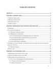


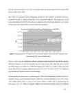

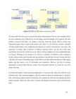


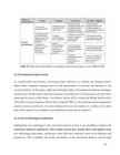


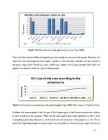
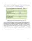


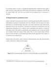


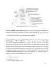
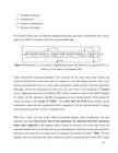


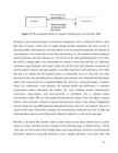


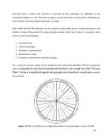


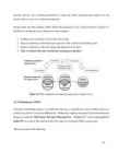


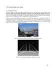
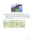


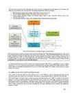
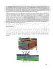

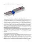

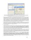


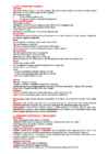


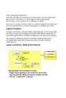

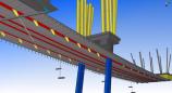
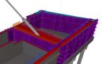

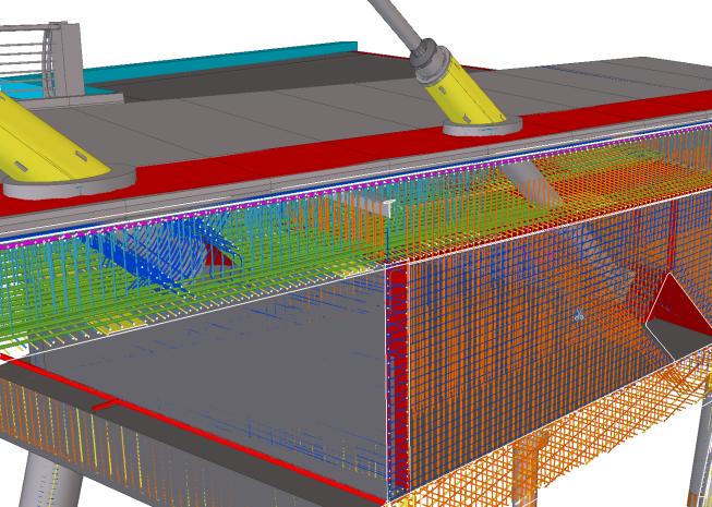
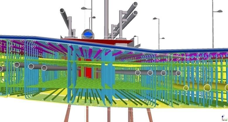
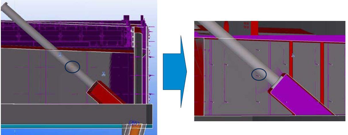
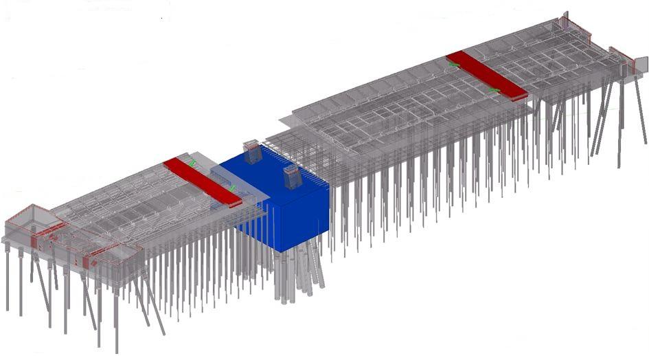
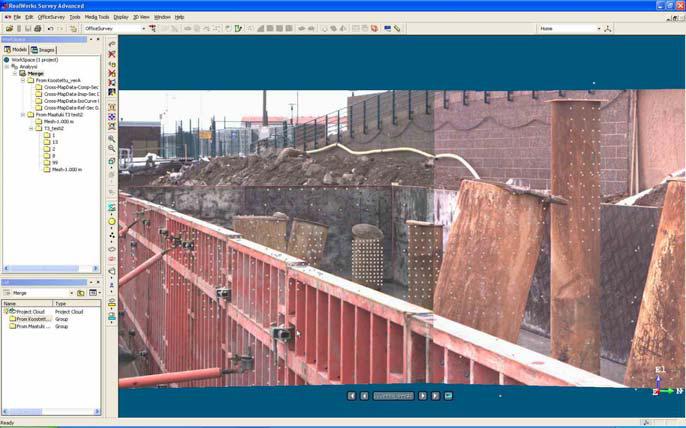
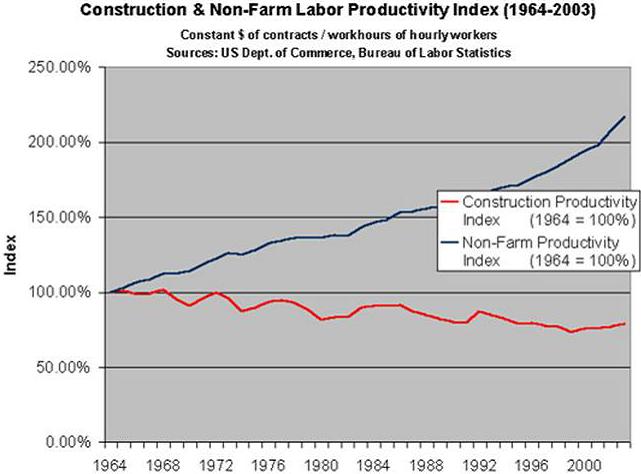
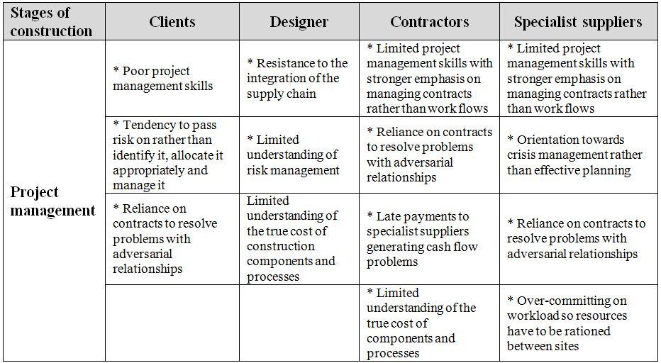

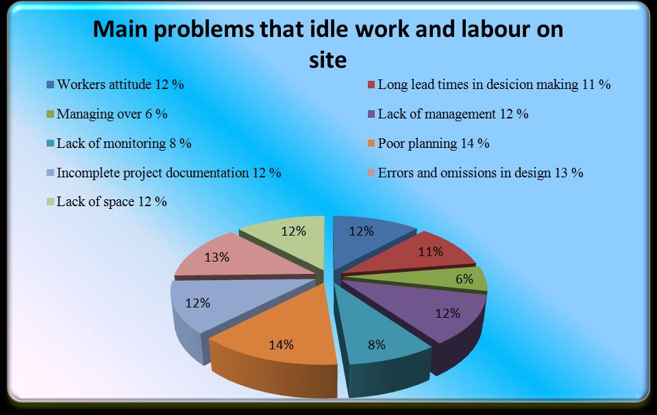
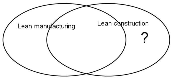
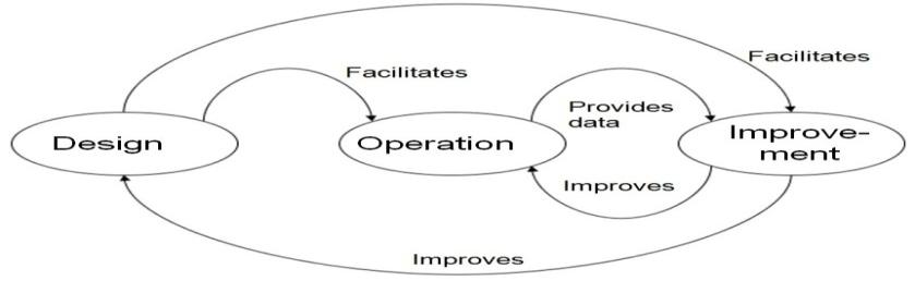

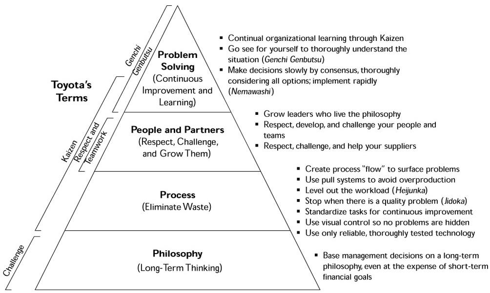
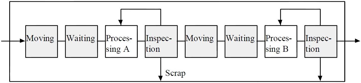
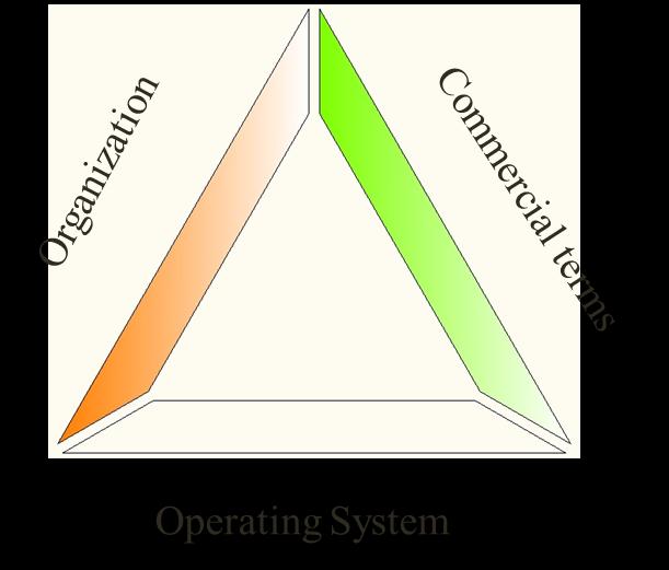
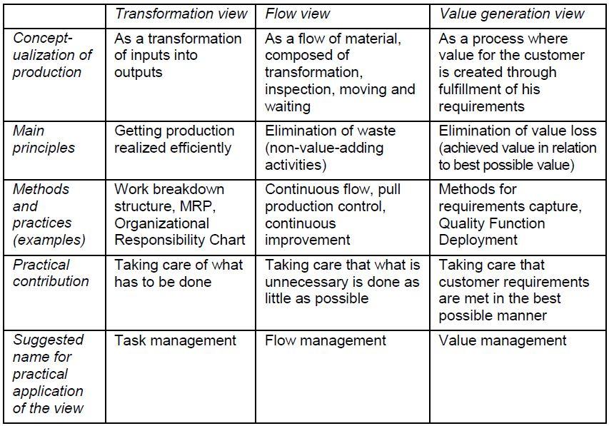
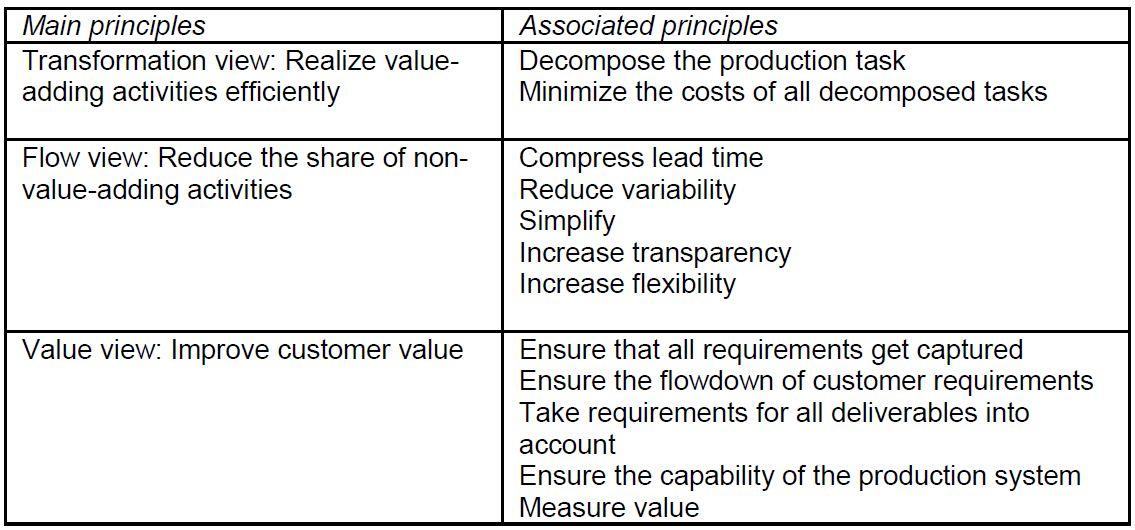
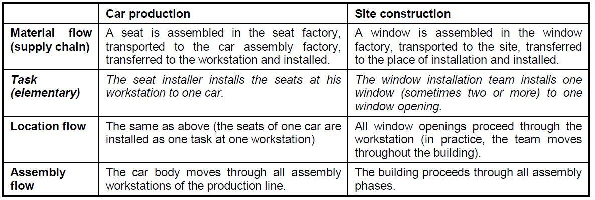
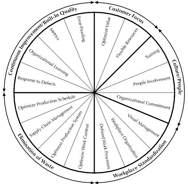
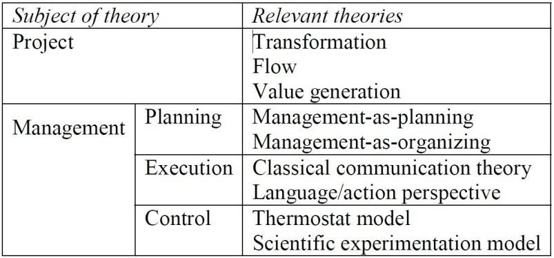
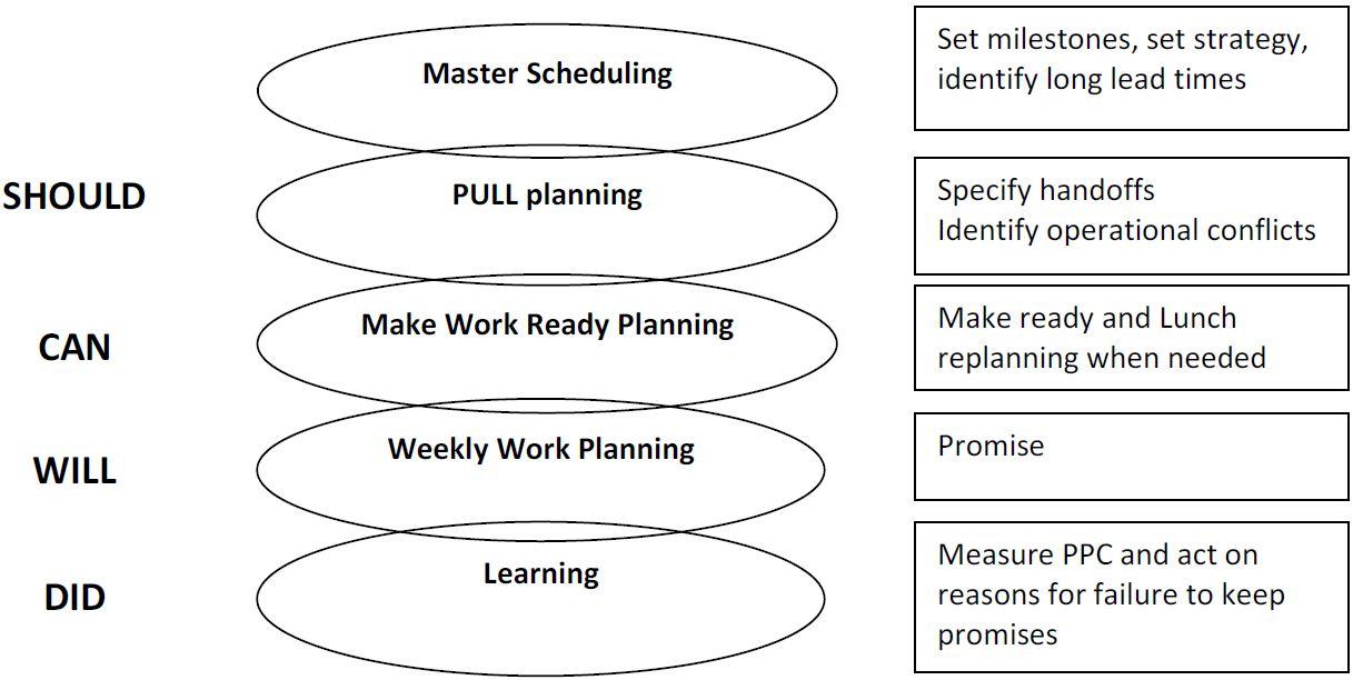
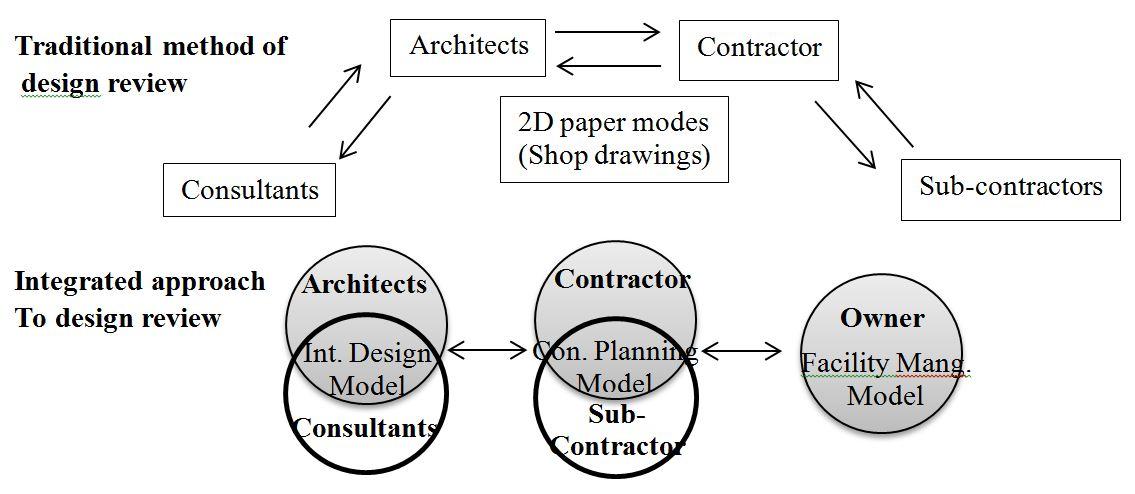
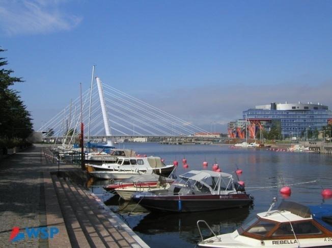
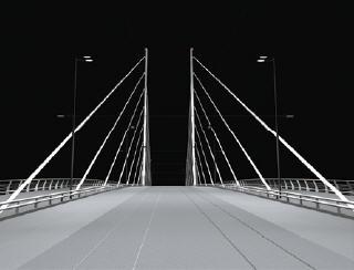
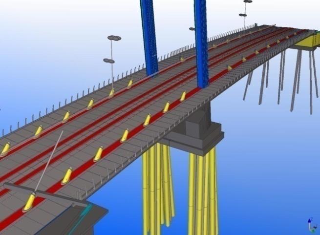
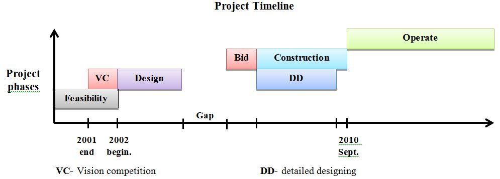


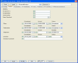
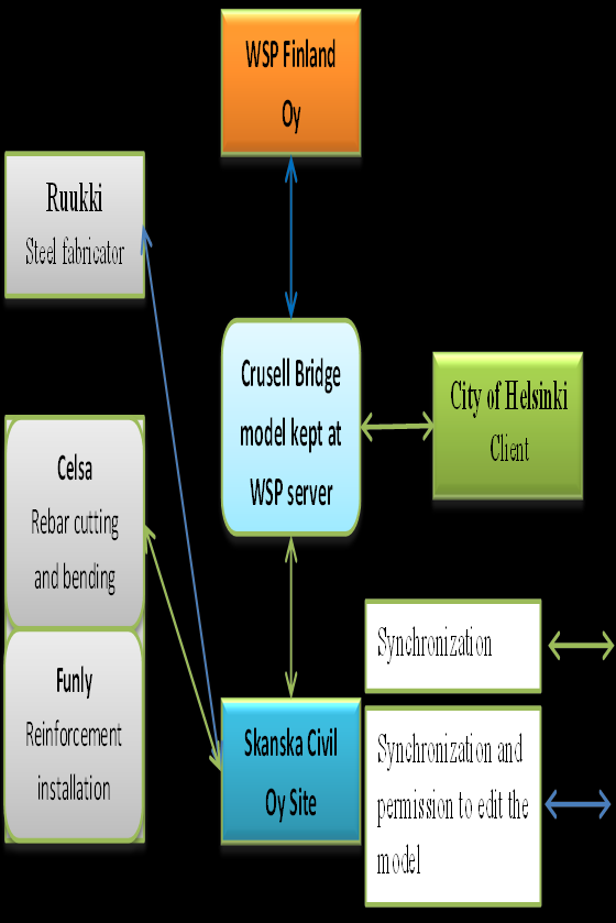
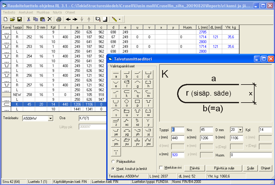
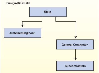
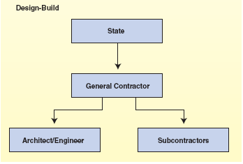
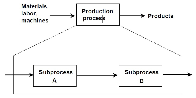
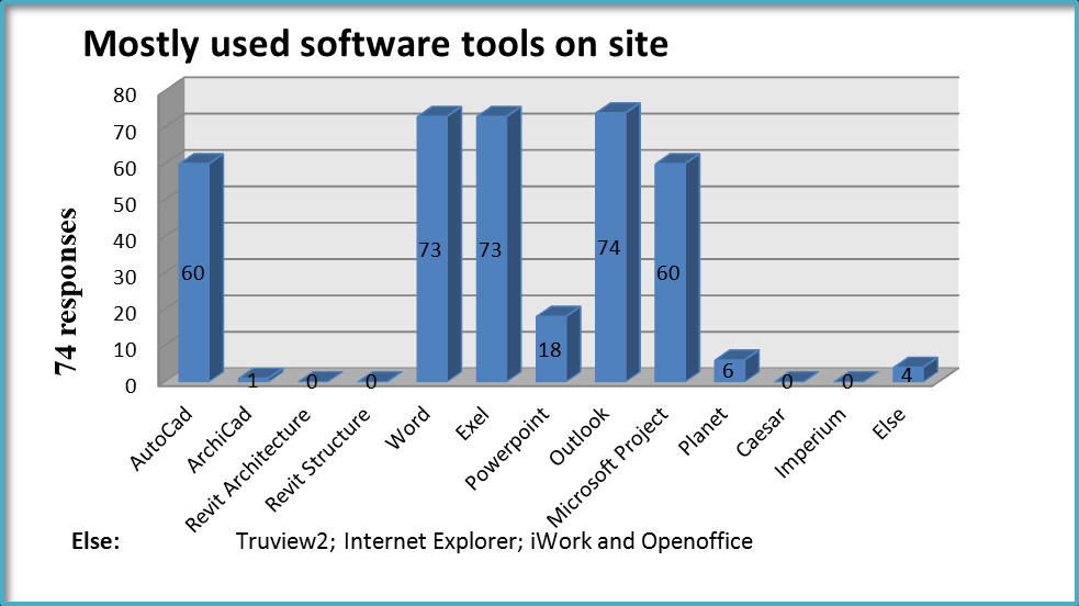

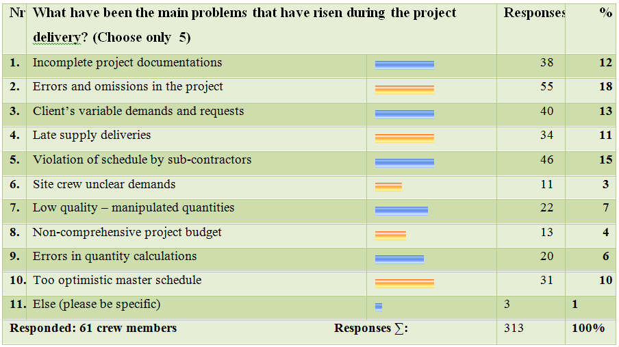
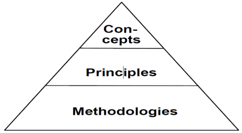
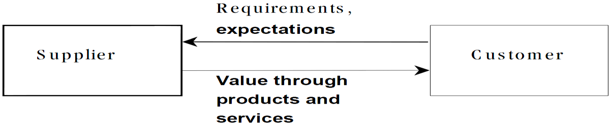
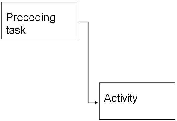
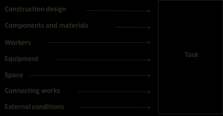
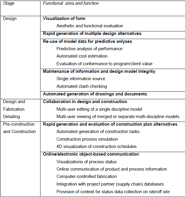
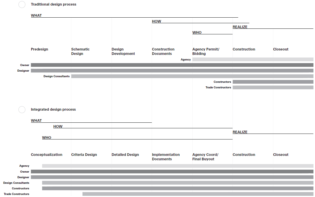


Kõik kommentaarid