Cat. No. W317-E1-11
SYSMAC
CPM1AProgrammable Controllers OPERATION MANUAL CPM1A Programmable ControllersOperation ManualRevised October 2007iv Notice :OMRON products are manufactured for use according to
proper procedures by a qualified
operator and only for the
purposes described in this manual.
The
following conventions are used to indicate and classify precautions in this manual. Always heed
the information
provided with
them .
Failure to heed precautions can
result in injury to people or dam-
age to property.
! DANGERIndicates an imminently
hazardous situation which, if not avoided, will result in death or
serious injury. Additionally,
there may be severe property damage.
! WARNINGIndicates a potentially hazardous situation which, if not avoided,
could result in death or
serious injury. Additionally, there may be severe property damage.
! CautionIndicates a potentially hazardous situation which, if not avoided, may result in
minor or
moderate injury, or property damage.
OMRON Product ReferencesAll OMRON products are
capitalized in this manual. The word “
Unit ” is also capitalized when it refers
to an OMRON product, regardless of whether or not it
appears in the proper name of the product.
The abbreviation “Ch,” which appears in some displays and on some OMRON products, often
means “word” and is
abbreviated “Wd” in documentation in this
sense .
The abbreviation “PC” means Programmable Controller and is not used as an abbreviation for any-
thing else .
Visual AidsThe following headings appear in the
left column of the manual to help you
locate different types of
information.
Note Indicates information of
particular interest for efficient and convenient operation
of the product.
1, 2, 3...1.
Indicates
lists of one sort or
another ,
such as procedures, checklists, etc.
OMRON, 1997All
rights reserved. No
part of this publication may be reproduced,
stored in a retrieval system, or transmitted, in any
form, or by any means,
mechanical , electronic, photocopying, recording, or otherwise,
without the
prior written permis-
sion of OMRON.
No patent
liability is assumed with respect to the use of the information contained herein. Moreover, because OMRON is
constantly striving to
improve its high-quality products, the information contained in this manual is
subject to
change without notice. Every precaution has been taken in the
preparation of this manual. Nevertheless, OMRON assumes no
responsibility for errors or omissions. Neither is any liability assumed for damages resulting from the use of the informa-
tion contained in this publication.
vviTABLE OF CONTENTSPRECAUTIONS . . . . . . . . . . . . . . . . . . . . . . . . . . . . . . . . . xv1 Intended
Audience . . . . . . . . . . . . . . . . . . . . . . . . . . . . . . . . . . . . . . . . . . . . . . . . . . . . . . . . . . .
xvi
2 General Precautions . . . . . . . . . . . . . . . . . . . . . . . . . . . . . . . . . . . . . . . . . . . . . . . . . . . . . . . . . .
xvi
3
Safety Precautions . . . . . . . . . . . . . . . . . . . . . . . . . . . . . . . . . . . . . . . . . . . . . . . . . . . . . . . . . . .
xvi
4
Operating Environment Precautions . . . . . . . . . . . . . . . . . . . . . . . . . . . . . . . . . . . . . . . . . . . . .
xvii 5
Application Precautions . . . . . . . . . . . . . . . . . . . . . . . . . . . . . . . . . . . . . . . . . . . . . . . . . . . . . .
xviii 6 EC Directives . . . . . . . . . . . . . . . . . . . . . . . . . . . . . . . . . . . . . . . . . . . . . . . . . . . . . . . . . . . . . .
xxi
7 Revised Specifications . . . . . . . . . . . . . . . . . . . . . . . . . . . . . . . . . . . . . . . . . . . . . . . . . . . . . . .
xxiii
SECTION 1
Introduction . . . . . . . . . . . . . . . . . . . . . . . . . . . . . . . . . . . . 11-1
CPM1A
Features and
Functions . . . . . . . . . . . . . . . . . . . . . . . . . . . . . . . . . . . . . . . . . . . .
2
1-2
System Configuration . . . . . . . . . . . . . . . . . . . . . . . . . . . . . . . . . . . . . . . . . . . . . . . . . . . . .
10
SECTION 2
Unit Specifications and Components . . . . . . . . . . . . . . . . 212-1
Specifications . . . . . . . . . . . . . . . . . . . . . . . . . . . . . . . . . . . . . . . . . . . . . . . . . . . . . . . . . . .
22
2-2
Unit Components . . . . . . . . . . . . . . . . . . . . . . . . . . . . . . . . . . . . . . . . . . . . . . . . . . . . . . . .
31
SECTION 3
Installation and Wiring . . . . . . . . . . . . . . . . . . . . . . . . . . . 413-1
Design Precautions . . . . . . . . . . . . . . . . . . . . . . . . . . . . . . . . . . . . . . . . . . . . . . . . . . . . . . .
42
3-2
Selecting an Installation Site . . . . . . . . . . . . . . . . . . . . . . . . . . . . . . . . . . . . . . . . . . . . . . .
43
3-3
Installing the CPM1A . . . . . . . . . . . . . . . . . . . . . . . . . . . . . . . . . . . . . . . . . . . . . . . . . . . . .
45
3-4
Wiring and Connections . . . . . . . . . . . . . . . . . . . . . . . . . . . . . . . . . . . . . . . . . . . . . . . . . . .
50
SECTION 4
Using Peripheral Devices . . . . . . . . . . . . . . . . . . . . . . . . . . 774-1
Support Software Capabilities . . . . . . . . . . . . . . . . . . . . . . . . . . . . . . . . . . . . . . . . . . . . . .
78
4-2
Using a Programming Console . . . . . . . . . . . . . . . . . . . . . . . . . . . . . . . . . . . . . . . . . . . . .
84
4-3
Programming Console Operations . . . . . . . . . . . . . . . . . . . . . . . . . . . . . . . . . . . . . . . . . . .
90
4-4
Programming Example . . . . . . . . . . . . . . . . . . . . . . . . . . . . . . . . . . . . . . . . . . . . . . . . . . . .
112
SECTION 5
Test Runs and Error Processing . . . . . . . . . . . . . . . . . . . . 1195-1
Initial System Checks and Test Run Procedure . . . . . . . . . . . . . . . . . . . . . . . . . . . . . . . . .
120
5-2
The CPM1A
Cycle . . . . . . . . . . . . . . . . . . . . . . . . . . . . . . . . . . . . . . . . . . . . . . . . . . . . . . .
122
5-3
Self-diagnosis Functions . . . . . . . . . . . . . . . . . . . . . . . . . . . . . . . . . . . . . . . . . . . . . . . . . .
123
5-4
Programming Console Operation Errors . . . . . . . . . . . . . . . . . . . . . . . . . . . . . . . . . . . . . .
125
5-5
Programming Errors . . . . . . . . . . . . . . . . . . . . . . . . . . . . . . . . . . . . . . . . . . . . . . . . . . . . . .
125
5-6
Troubleshooting Flowcharts . . . . . . . . . . . . . . . . . . . . . . . . . . . . . . . . . . . . . . . . . . . . . . . .
127
5-7
Maintenance Inspections . . . . . . . . . . . . . . . . . . . . . . . . . . . . . . . . . . . . . . . . . . . . . . . . . .
135
5-8
Handling Precautions . . . . . . . . . . . . . . . . . . . . . . . . . . . . . . . . . . . . . . . . . . . . . . . . . . . . .
136
SECTION 6
Expansion Memory Unit . . . . . . . . . . . . . . . . . . . . . . . . . . 1376-1
Overview . . . . . . . . . . . . . . . . . . . . . . . . . . . . . . . . . . . . . . . . . . . . . . . . . . . . . . . . . . . . . .
138
6-2
Specifications and Nomenclature . . . . . . . . . . . . . . . . . . . . . . . . . . . . . . . . . . . . . . . . . . .
139
6-3
Handling . . . . . . . . . . . . . . . . . . . . . . . . . . . . . . . . . . . . . . . . . . . . . . . . . . . . . . . . . . . . . . .
140
viiTABLE OF CONTENTSAppendicesA Standard Models . . . . . . . . . . . . . . . . . . . . . . . . . . . . . . . . . . . . . . . . . . . . . . . . . . . . . . . . . . .
147
B Dimensions . . . . . . . . . . . . . . . . . . . . . . . . . . . . . . . . . . . . . . . . . . . . . . . . . . . . . . . . . . . . . . . .
151
Glossary . . . . . . . . . . . . . . . . . . . . . . . . . . . . . . . . . . . . . . . 159Index . . . . . . . . . . . . . . . . . . . . . . . . . . . . . . . . . . . . . . . . . . 175 Revision History . . . . . . . . . . . . . . . . . . . . . . . . . . . . . . . . . 179viiiAbout this Manual:The CPM1A is a compact, high-
speed Programmable Controller (PC)
designed for
control operations in
systems requiring from 10 to 100 I/O
points per PC. There are two manuals describing the setup and
operation of the CPM1A: the
CPM1A Operation Manual (this manual) and the
CPM1/CPM1A/CPM2A/
CPM2C/SRM1(-V2) Programming Manual (W353).
This manual describes the system configuration and installation of the CPM1A and provides a
basic explanation of operating procedures for the Programming Consoles. It also introduces the capabilities of
the SYSMAC Support Software (SSS). Read this manual
first to acquaint yourself with the CPM1A.
The
CPM1/CPM1A/CPM2A/CPM2C/SRM1(-V2) Programming Manual (W353) provides detailed
descriptions of the CPM1A’s programming functions. The
SYSMAC Support Software Operation Manu-
als: Basics and
C-series PCs (W247 and W248)
provide descriptions of SSS operations for the CPM1A
and
other SYSMAC C-series PCs. The
SYSMAC-CPT Support Software Quick Start Guide (W332) and
User Manual (W333) provide descriptions of
ladder diagram operations in the
Windows environment. The
WS02-CXPC1-E-V72 CX-Programmer Ver. 7.2 Operation Manual (W446) and the
WS02-CXPC1-E-V7
CX-Programmer Ver. 7.2 Operation Manual: Function Blocks /Structured Text (W447) provide
details of
operations for the WS02-CXPC1-E CX-Programmer. The
CompoBus/S Operation Manual (W266) pro-
vides CompoBus/S communications specifications and describes CompoBus/S application methods.
Please read this manual carefully and be
sure you
understand the information provide
before attempting
to
install and operate the CPM1A.
Section 1 gives a brief overview of the steps involved in developing of a CPM1A System, describes the
possible system configurations, and describes the CPM1A’s
special features and functions.
Section 2 provides the technical specifications of the
Units that go together to create a CPM1A PC and
describes the main components of the Units.
Section 3 describes how to install and
wire a CPM1A PC.
Section 4 describes SSS capabilities, how to connect the Programming Console, and how to
perform the
various Programming Console operations.
Section 5 describes how to perform a test run and how to diagnose and
correct the hardware and
soft -
ware errors that can
occur during PC operation.
Section 6 describes how to use the CPM1-EMU01-V1 Expansion Memory Unit.
Follow the handling pre-
cautions and procedures to properly use the Unit.
Appendix A provides tables of CPM1A Units and
related products.
Appendix B provides the dimensions of CPM1A Units.
! WARNING Failure to read and understand the information provided in this manual may result in
personal injury or death, damage to the product, or product failure. Please read each
section in its entirety and be sure you understand the information provided in the section
and related sections before attempting any of the procedures or operations
given .
ixTABLE OF CONTENTSxRead and Understand this ManualPlease read and understand this manual before using the product. Please consult your OMRON
representative if you have any questions or comments.
Warranty and Limitations of LiabilityWARRANTYÁÁÁÁÁÁÁÁÁÁÁÁÁÁÁÁÁÁÁÁÁÁÁÁÁÁÁÁÁÁÁÁÁ
ÁÁÁÁÁÁÁÁÁÁÁÁÁÁÁÁÁÁÁÁÁÁÁÁÁÁÁÁÁÁÁÁÁ
OMRON’s exclusive warranty is that the products are free from defects in materials and workmanship for
ÁÁÁÁÁÁÁÁÁÁÁÁÁÁÁÁÁÁÁÁÁÁÁÁÁÁÁÁÁÁÁÁ
Á
a
period of one
year (or other period if specified) from
date of sale by OMRON.
Á ÁÁÁÁÁÁÁÁÁÁÁÁÁÁÁÁÁÁÁÁÁÁÁÁÁÁÁÁÁÁÁ
Á
OMRON
MAKES NO WARRANTY OR REPRESENTATION,
EXPRESS OR IMPLIED, REGARDING
Á ÁÁÁÁÁÁÁÁÁÁÁÁÁÁÁÁÁÁÁÁÁÁÁÁÁÁÁÁÁÁÁ
Á
NON–INFRINGEMENT, MERCHANTABILITY, OR FITNESS FOR PARTICULAR
PURPOSE OF THE
Á ÁÁÁÁÁÁÁÁÁÁÁÁÁÁÁÁÁÁÁÁÁÁÁÁÁÁÁÁÁÁÁ
Á
PRODUCTS. ANY BUYER OR USER ACKNOWLEDGES THAT THE BUYER OR USER
ALONE HAS
Á ÁÁÁÁÁÁÁÁÁÁÁÁÁÁÁÁÁÁÁÁÁÁÁÁÁÁÁÁÁÁÁ
Á
DETERMINED THAT THE PRODUCTS WILL SUITABLY MEET THE
REQUIREMENTS OF THEIR
INTENDED USE. OMRON DISCLAIMS ALL OTHER WARRANTIES, EXPRESS OR IMPLIED.
Á ÁÁÁÁÁÁÁÁÁÁÁÁÁÁÁÁÁÁÁÁÁÁÁÁÁÁÁÁÁÁÁ
Á
ÁÁÁÁÁÁÁÁÁÁÁÁÁÁÁÁÁÁÁÁÁÁÁÁÁÁÁÁÁÁÁÁÁ
ÁÁÁÁÁÁÁÁÁÁÁÁÁÁÁÁÁÁÁÁÁÁÁÁÁÁÁÁÁÁÁÁÁ
LIMITATIONS OF LIABILITYÁÁÁÁÁÁÁÁÁÁÁÁÁÁÁÁÁÁÁÁÁÁÁÁÁÁÁÁÁÁÁÁ
Á
OMRON
SHALL NOT BE
RESPONSIBLE FOR SPECIAL,
INDIRECT , OR CONSEQUENTIAL
ÁÁÁÁÁÁÁÁÁÁÁÁÁÁÁÁÁÁÁÁÁÁÁÁÁÁÁÁÁÁÁÁÁ
ÁÁÁÁÁÁÁÁÁÁÁÁÁÁÁÁÁÁÁÁÁÁÁÁÁÁÁÁÁÁÁÁÁ
DAMAGES, LOSS OF PROFITS OR COMMERCIAL LOSS IN ANY WAY CONNECTED WITH THE
ÁÁÁÁÁÁÁÁÁÁÁÁÁÁÁÁÁÁÁÁÁÁÁÁÁÁÁÁÁÁÁÁ
Á
PRODUCTS, WHETHER SUCH CLAIM IS
BASED ON CONTRACT, WARRANTY, NEGLIGENCE, OR
STRICT LIABILITY.
Á ÁÁÁÁÁÁÁÁÁÁÁÁÁÁÁÁÁÁÁÁÁÁÁÁÁÁÁÁÁÁÁ
Á
Á ÁÁÁÁÁÁÁÁÁÁÁÁÁÁÁÁÁÁÁÁÁÁÁÁÁÁÁÁÁÁÁ
Á
In no event shall the responsibility of OMRON for any act exceed the
individual price of the product on
Á ÁÁÁÁÁÁÁÁÁÁÁÁÁÁÁÁÁÁÁÁÁÁÁÁÁÁÁÁÁÁÁ
Á
which liability is asserted.
Á ÁÁÁÁÁÁÁÁÁÁÁÁÁÁÁÁÁÁÁÁÁÁÁÁÁÁÁÁÁÁÁ
Á
IN NO EVENT SHALL OMRON BE RESPONSIBLE FOR WARRANTY,
REPAIR , OR OTHER CLAIMS
Á ÁÁÁÁÁÁÁÁÁÁÁÁÁÁÁÁÁÁÁÁÁÁÁÁÁÁÁÁÁÁÁ
Á
REGARDING THE PRODUCTS
UNLESS OMRON’S
ANALYSIS CONFIRMS THAT THE PRODUCTS
Á ÁÁÁÁÁÁÁÁÁÁÁÁÁÁÁÁÁÁÁÁÁÁÁÁÁÁÁÁÁÁÁ
Á
WERE PROPERLY HANDLED, STORED, INSTALLED, AND MAINTAINED AND NOT SUBJECT TO
Á ÁÁÁÁÁÁÁÁÁÁÁÁÁÁÁÁÁÁÁÁÁÁÁÁÁÁÁÁÁÁÁ
Á
CONTAMINATION, ABUSE, MISUSE, OR INAPPROPRIATE MODIFICATION OR REPAIR.
ÁÁÁÁÁÁÁÁÁÁÁÁÁÁÁÁÁÁÁÁÁÁÁÁÁÁÁÁÁÁÁÁÁ
xiApplication ConsiderationsÁÁÁÁÁÁÁÁÁÁÁÁÁÁÁÁÁÁÁÁÁÁÁÁÁÁÁÁÁÁÁÁÁ
SUITABILITY FOR USEÁÁÁÁÁÁÁÁÁÁÁÁÁÁÁÁÁÁÁÁÁÁÁÁÁÁÁÁÁÁÁÁÁ
OMRON shall not be responsible for conformity with any standards, codes, or regulations that
apply to
ÁÁÁÁÁÁÁÁÁÁÁÁÁÁÁÁÁÁÁÁÁÁÁÁÁÁÁÁÁÁÁÁ
Á
the combination of products in the customer’s application or use of the products.
Á ÁÁÁÁÁÁÁÁÁÁÁÁÁÁÁÁÁÁÁÁÁÁÁÁÁÁÁÁÁÁÁ
Á
At the customer’s request, OMRON will provide
applicable third
party certification documents identifying
Á ÁÁÁÁÁÁÁÁÁÁÁÁÁÁÁÁÁÁÁÁÁÁÁÁÁÁÁÁÁÁÁ
Á
ratings and limitations of use that apply to the products. This information by itself is not sufficient for a
Á ÁÁÁÁÁÁÁÁÁÁÁÁÁÁÁÁÁÁÁÁÁÁÁÁÁÁÁÁÁÁÁ
Á
complete determination of the suitability of the products in combination with the end product,
machine ,
Á ÁÁÁÁÁÁÁÁÁÁÁÁÁÁÁÁÁÁÁÁÁÁÁÁÁÁÁÁÁÁÁ
Á
system, or other application or use.
Á ÁÁÁÁÁÁÁÁÁÁÁÁÁÁÁÁÁÁÁÁÁÁÁÁÁÁÁÁÁÁÁ
Á
The following are some
examples of applications for which particular
attention must be given. This is not
Á ÁÁÁÁÁÁÁÁÁÁÁÁÁÁÁÁÁÁÁÁÁÁÁÁÁÁÁÁÁÁÁ
Á
intended to be an exhaustive list of all possible uses of the products, nor is it intended to imply that the
Á ÁÁÁÁÁÁÁÁÁÁÁÁÁÁÁÁÁÁÁÁÁÁÁÁÁÁÁÁÁÁÁ
Á
uses listed may be suitable for the products:
Á ÁÁÁÁÁÁÁÁÁÁÁÁÁÁÁÁÁÁÁÁÁÁÁÁÁÁÁÁÁÁÁ
Á
• Outdoor use, uses involving potential chemical contamination or
electrical interference, or
conditions Á ÁÁÁÁÁÁÁÁÁÁÁÁÁÁÁÁÁÁÁÁÁÁÁÁÁÁÁÁÁÁÁ
Á
or uses not described in this manual.
Á ÁÁÁÁÁÁÁÁÁÁÁÁÁÁÁÁÁÁÁÁÁÁÁÁÁÁÁÁÁÁÁ
Á
• Nuclear energy control systems, combustion systems, railroad systems, aviation systems, medical
Á ÁÁÁÁÁÁÁÁÁÁÁÁÁÁÁÁÁÁÁÁÁÁÁÁÁÁÁÁÁÁÁ
Á
equipment , amusement
machines , vehicles, safety equipment, and installations subject to separate
industry or
government regulations.
Á ÁÁÁÁÁÁÁÁÁÁÁÁÁÁÁÁÁÁÁÁÁÁÁÁÁÁÁÁÁÁÁ
Á
Á ÁÁÁÁÁÁÁÁÁÁÁÁÁÁÁÁÁÁÁÁÁÁÁÁÁÁÁÁÁÁÁ
Á
• Systems, machines, and equipment that could
present a risk to life or property.
Á ÁÁÁÁÁÁÁÁÁÁÁÁÁÁÁÁÁÁÁÁÁÁÁÁÁÁÁÁÁÁÁ
Á
Please know and observe all prohibitions of use applicable to the products.
Á ÁÁÁÁÁÁÁÁÁÁÁÁÁÁÁÁÁÁÁÁÁÁÁÁÁÁÁÁÁÁÁ
Á
Á ÁÁÁÁÁÁÁÁÁÁÁÁÁÁÁÁÁÁÁÁÁÁÁÁÁÁÁÁÁÁÁ
Á
NEVER USE THE PRODUCTS FOR AN APPLICATION INVOLVING SERIOUS RISK TO LIFE OR
PROPERTY WITHOUT ENSURING THAT THE SYSTEM AS A
WHOLE HAS BEEN DESIGNED TO
Á ÁÁÁÁÁÁÁÁÁÁÁÁÁÁÁÁÁÁÁÁÁÁÁÁÁÁÁÁÁÁÁ
Á
ADDRESS THE RISKS, AND THAT THE OMRON PRODUCTS ARE PROPERLY RATED AND
Á ÁÁÁÁÁÁÁÁÁÁÁÁÁÁÁÁÁÁÁÁÁÁÁÁÁÁÁÁÁÁÁ
Á
INSTALLED FOR THE INTENDED USE
WITHIN THE
OVERALL EQUIPMENT OR SYSTEM.
Á ÁÁÁÁÁÁÁÁÁÁÁÁÁÁÁÁÁÁÁÁÁÁÁÁÁÁÁÁÁÁÁ
Á
ÁÁÁÁÁÁÁÁÁÁÁÁÁÁÁÁÁÁÁÁÁÁÁÁÁÁÁÁÁÁÁÁÁ
ÁÁÁÁÁÁÁÁÁÁÁÁÁÁÁÁÁÁÁÁÁÁÁÁÁÁÁÁÁÁÁÁÁ
PROGRAMMABLE PRODUCTSÁÁÁÁÁÁÁÁÁÁÁÁÁÁÁÁÁÁÁÁÁÁÁÁÁÁÁÁÁÁÁÁ
Á
ÁÁÁÁÁÁÁÁÁÁÁÁÁÁÁÁÁÁÁÁÁÁÁÁÁÁÁÁÁÁÁÁÁ
ÁÁÁÁÁÁÁÁÁÁÁÁÁÁÁÁÁÁÁÁÁÁÁÁÁÁÁÁÁÁÁÁÁ
OMRON shall not be responsible for the user’s programming of a programmable product, or any
consequence thereof.
ÁÁÁÁÁÁÁÁÁÁÁÁÁÁÁÁÁÁÁÁÁÁÁÁÁÁÁÁÁÁÁÁ
Á
ÁÁÁÁÁÁÁÁÁÁÁÁÁÁÁÁÁÁÁÁÁÁÁÁÁÁÁÁÁÁÁÁÁ
xiiDisclaimersÁÁÁÁÁÁÁÁÁÁÁÁÁÁÁÁÁÁÁÁÁÁÁÁÁÁÁÁÁÁÁÁÁ
CHANGE IN SPECIFICATIONSÁÁÁÁÁÁÁÁÁÁÁÁÁÁÁÁÁÁÁÁÁÁÁÁÁÁÁÁÁÁÁÁ
Á
Product specifications and accessories may be changed at any time based on improvements and other
ÁÁÁÁÁÁÁÁÁÁÁÁÁÁÁÁÁÁÁÁÁÁÁÁÁÁÁÁÁÁÁÁÁ
ÁÁÁÁÁÁÁÁÁÁÁÁÁÁÁÁÁÁÁÁÁÁÁÁÁÁÁÁÁÁÁÁÁ
reasons.
ÁÁÁÁÁÁÁÁÁÁÁÁÁÁÁÁÁÁÁÁÁÁÁÁÁÁÁÁÁÁÁÁ
Á
It is our practice to change model
numbers when published ratings or features are changed, or when
Á ÁÁÁÁÁÁÁÁÁÁÁÁÁÁÁÁÁÁÁÁÁÁÁÁÁÁÁÁÁÁÁ
Á
significant
construction changes are made.
However , some specifications of the products may be
Á ÁÁÁÁÁÁÁÁÁÁÁÁÁÁÁÁÁÁÁÁÁÁÁÁÁÁÁÁÁÁÁ
Á
changed without any notice. When in doubt, special model numbers may be assigned to fix or establish
Á ÁÁÁÁÁÁÁÁÁÁÁÁÁÁÁÁÁÁÁÁÁÁÁÁÁÁÁÁÁÁÁ
Á
key specifications for your application on your request. Please consult with your OMRON representative
Á ÁÁÁÁÁÁÁÁÁÁÁÁÁÁÁÁÁÁÁÁÁÁÁÁÁÁÁÁÁÁÁ
Á
at any time to confirm actual specifications of purchased products.
ÁÁÁÁÁÁÁÁÁÁÁÁÁÁÁÁÁÁÁÁÁÁÁÁÁÁÁÁÁÁÁÁÁ
ÁÁÁÁÁÁÁÁÁÁÁÁÁÁÁÁÁÁÁÁÁÁÁÁÁÁÁÁÁÁÁÁÁ
DIMENSIONS AND WEIGHTSÁÁÁÁÁÁÁÁÁÁÁÁÁÁÁÁÁÁÁÁÁÁÁÁÁÁÁÁÁÁÁÁ
Á
Dimensions and weights are nominal and are not to be used for manufacturing purposes,
even when
ÁÁÁÁÁÁÁÁÁÁÁÁÁÁÁÁÁÁÁÁÁÁÁÁÁÁÁÁÁÁÁÁÁ
ÁÁÁÁÁÁÁÁÁÁÁÁÁÁÁÁÁÁÁÁÁÁÁÁÁÁÁÁÁÁÁÁÁ
tolerances are shown.
ÁÁÁÁÁÁÁÁÁÁÁÁÁÁÁÁÁÁÁÁÁÁÁÁÁÁÁÁÁÁÁÁ
Á
ÁÁÁÁÁÁÁÁÁÁÁÁÁÁÁÁÁÁÁÁÁÁÁÁÁÁÁÁÁÁÁÁÁ
ÁÁÁÁÁÁÁÁÁÁÁÁÁÁÁÁÁÁÁÁÁÁÁÁÁÁÁÁÁÁÁÁÁ
PERFORMANCE DATAÁÁÁÁÁÁÁÁÁÁÁÁÁÁÁÁÁÁÁÁÁÁÁÁÁÁÁÁÁÁÁÁÁ
Performance data given in this manual is provided as a guide for the user in determining suitability and
ÁÁÁÁÁÁÁÁÁÁÁÁÁÁÁÁÁÁÁÁÁÁÁÁÁÁÁÁÁÁÁÁ
Á
does not constitute a warranty. It may
represent the result of OMRON’s test conditions, and the
users Á ÁÁÁÁÁÁÁÁÁÁÁÁÁÁÁÁÁÁÁÁÁÁÁÁÁÁÁÁÁÁÁ
Á
must correlate it to actual application requirements. Actual performance is subject to the OMRON
Warranty and Limitations of Liability.
Á ÁÁÁÁÁÁÁÁÁÁÁÁÁÁÁÁÁÁÁÁÁÁÁÁÁÁÁÁÁÁÁ
Á
ÁÁÁÁÁÁÁÁÁÁÁÁÁÁÁÁÁÁÁÁÁÁÁÁÁÁÁÁÁÁÁÁÁ
ÁÁÁÁÁÁÁÁÁÁÁÁÁÁÁÁÁÁÁÁÁÁÁÁÁÁÁÁÁÁÁÁÁ
ERRORS AND OMISSIONSÁÁÁÁÁÁÁÁÁÁÁÁÁÁÁÁÁÁÁÁÁÁÁÁÁÁÁÁÁÁÁÁ
Á
The information in this manual has been carefully checked and is believed to be accurate; however, no
ÁÁÁÁÁÁÁÁÁÁÁÁÁÁÁÁÁÁÁÁÁÁÁÁÁÁÁÁÁÁÁÁÁ
ÁÁÁÁÁÁÁÁÁÁÁÁÁÁÁÁÁÁÁÁÁÁÁÁÁÁÁÁÁÁÁÁÁ
responsibility is assumed for clerical, typographical, or proofreading errors, or omissions.
ÁÁÁÁÁÁÁÁÁÁÁÁÁÁÁÁÁÁÁÁÁÁÁÁÁÁÁÁÁÁÁÁ
Á
ÁÁÁÁÁÁÁÁÁÁÁÁÁÁÁÁÁÁÁÁÁÁÁÁÁÁÁÁÁÁÁÁÁ
xiiixivPRECAUTIONSThis section provides general precautions for using the Programmable Controller (PC) and related devices.
The information contained in this section is important for the safe and reliable application of the Programmable Con-
troller. You must read this section and understand the information contained before attempting to set up or operate a
PC system.1 Intended Audience . . . . . . . . . . . . . . . . . . . . . . . . . . . . . . . . . . . . . . . . . . . . . . . . . . . . . . . . . . . .
xvi
2 General Precautions . . . . . . . . . . . . . . . . . . . . . . . . . . . . . . . . . . . . . . . . . . . . . . . . . . . . . . . . . . .
xvi
3 Safety Precautions . . . . . . . . . . . . . . . . . . . . . . . . . . . . . . . . . . . . . . . . . . . . . . . . . . . . . . . . . . . .
xvi
4 Operating Environment Precautions . . . . . . . . . . . . . . . . . . . . . . . . . . . . . . . . . . . . . . . . . . . . . .
xvii
5 Application Precautions . . . . . . . . . . . . . . . . . . . . . . . . . . . . . . . . . . . . . . . . . . . . . . . . . . . . . . . .
xviii
6 EC Directives . . . . . . . . . . . . . . . . . . . . . . . . . . . . . . . . . . . . . . . . . . . . . . . . . . . . . . . . . . . . . . . .
xxi
7 Revised Specifications . . . . . . . . . . . . . . . . . . . . . . . . . . . . . . . . . . . . . . . . . . . . . . . . . . . . . . . . .
xxiii
xvSafety Precautions71Intended AudienceThis manual is intended for the following personnel, who must also have knowl-
edge of electrical systems (an electrical engineer or the
equivalent ).
• Personnel in
charge of installing FA systems.
• Personnel in charge of designing FA systems.
• Personnel in charge of managing FA systems and facilities.
2General PrecautionsThe user must operate the product according to the performance specifications
described in the operation manuals.
Before using the product under conditions which are not described in the manual
or applying the product to nuclear control systems, railroad systems, aviation
systems, vehicles, combustion systems, medical equipment, amusement ma-
chines, safety equipment, and other systems, machines, and equipment that
may have a serious
influence on lives and property if used improperly, consult
your OMRON representative.
Make sure that the ratings and performance
characteristics of the product are
sufficient for the systems, machines, and equipment, and be sure to provide the
systems, machines, and equipment with
double safety mechanisms.
This manual provides information for programming and operating the Unit. Be
sure to read this manual before attempting to use the Unit and
keep this manual
close at
hand for
reference during operation.
! WARNING It is extremely important that a PC and all PC Units be used for the specified
purpose and under the specified conditions, especially in applications that can
directly or indirectly
affect human life. You must consult with your OMRON
representative before applying a PC System to the
above -mentioned
applications.
3Safety Precautions! WARNING Do not attempt to take any Unit apart
while the
power is being supplied. Doing so
may result in
electric shock .
! WARNING Do not
touch any of the
terminals or
terminal blocks while the power is being
supplied. Doing so may result in electric shock.
! WARNING Do not attempt to disassemble, repair, or modify any Units. Any attempt to do so
may result in malfunction,
fire , or electric shock.
! WARNING Provide safety
measures in
external circuits (i.e., not in the Programmable
Controller),
including the following
items , in
order to ensure safety in the system
if an abnormality occurs due to malfunction of the PC or another external
factor affecting the PC operation. Not doing so may result in serious accidents.
• Emergency stop circuits, interlock circuits,
limit circuits, and
similar safety
measures must be provided in external control circuits.
• The PC will
turn OFF all outputs when its self-diagnosis function detects any
error or when a severe failure
alarm (FALS) instruction is executed. As a coun-
termeasure for such errors, external safety measures must be provided to en-
sure safety in the system.
xviOperating Environment Precautions4• The PC outputs may
remain ON or OFF due to deposition or
burning of the
output relays or destruction of the output transistors. As a countermeasure for
such problems, external safety measures must be provided to ensure safety in
the system.
• When the 24-VDC output (
service power
supply to the PC) is overloaded or
short-circuited, the
voltage may
drop and result in the outputs being turned
OFF. As a countermeasure for such problems, external safety measures must
be provided to ensure safety in the system.
! WARNING When transferring programs to other nodes, or when
making changes to I/O
memory, confirm the safety of the destination
node before
transfer . Not doing so
may result in injury.
! CautionExecute online edit only after confirming that no
adverse effects will be caused
by extending the cycle time. Otherwise, the input
signals may not be readable.
! CautionTighten the screws on the terminal block of the AC Power Supply Unit to the
torque specified in the operation manual. The loose screws may result in burning
or malfunction.
! CautionWhen
connecting a personal computer or other peripheral
device to the CPM1A,
either
ground the 0 V side of the CPM1A or do not ground at all. Depending on
the
method of grounding, the 24-V power supply may short-
circuit ; do not
ground the 24-V side as shown in the following diagram.
Example: Connections where 24-V Power Supply Will Short-circuitNon-isolated DC
power supply
CPM1A
Peripheral device
4Operating Environment Precautions! CautionDo not operate the control system in the following
places :
• Locations subject to
direct sunlight.
• Locations subject to
temperatures or humidity
outside the range specified in
the specifications.
• Locations subject to condensation as the result of severe changes in tempera-
ture.
• Locations subject to corrosive or flammable gases.
• Locations subject to
dust (especially
iron dust) or salts.
• Locations subject to
exposure to water, oil, or chemicals.
• Locations subject to shock or vibration.
! CautionTake appropriate and sufficient countermeasures when installing systems in the
following locations:
xviiApplication Precautions5• Locations subject to static electricity or other forms of noise.
• Locations subject to strong electromagnetic fields.
• Locations subject to possible exposure to radioactivity.
• Locations close to power supplies.
! CautionThe operating environment of the PC System can have a large
effect on the lon-
gevity and
reliability of the system. Improper operating environments can
lead to
malfunction, failure, and other unforeseeable problems with the PC System. Be
sure that the operating environment is within the specified conditions at installa-
tion and remains within the specified conditions during the life of the system.
5Application PrecautionsObserve the following precautions when using the PC System.
! WARNING Always heed
these precautions. Failure to abide by the following precautions
could lead to serious or possibly
fatal injury.
• Always connect to a ground of 100 Ω or less when installing the Units. Not con-
necting to a ground of 100 Ω or less may result in electric shock.
• Always turn off the power supply to the PC before attempting any of the follow-
ing. Not
turning off the power supply may result in malfunction or electric
shock.
• Mounting or dismounting I/O Units, CPU Units, or any other Units.
• Assembling the Units.
• Connecting or wiring the cables.
• Connecting or disconnecting the connectors.
! CautionFailure to abide by the following precautions could lead to faulty operation of the
PC or the system, or could damage the PC or PC Units. Always heed these pre-
cautions.
• Fail-safe measures must be taken by the customer to ensure safety in the
event of incorrect, missing, or abnormal signals caused by broken
signal lines,
momentary power interruptions, or other
causes .
•
Construct a control circuit so that power supply for the I/O circuits does not
come ON before power supply for the Unit. If power supply for the I/O circuits
comes ON before power supply for the Unit, normal operation may be tempo-
rarily interrupted.
• If the operating mode is changed from RUN or
MONITOR mode to
PROGRAM mode, with the IOM
Hold Bit ON, the output will hold the most recent
status . In
such a
case , ensure that the external
load does not exceed specifications. (If
operation is stopped because of an operation error (including FALS instruc-
tions), the
values in the
internal memory of the CPU Unit will be saved, but the
outputs will all turn OFF.)
• Always use the power supply voltage specified in the operation manuals. An
incorrect voltage may result in malfunction or burning.
• Take appropriate measures to ensure that the specified power with the rated
voltage and
frequency is supplied. Be particularly careful in places where the
power supply is unstable. An incorrect power supply may result in malfunction.
• Install external breakers and take other safety measures against short-circuit-
ing in external wiring. Insufficient safety measures against short-circuiting may
result in burning.
xviiiApplication Precautions5• Do not apply voltages to the Input Units in
excess of the rated input voltage.
Excess voltages may result in burning.
• Do not apply voltages or connect loads to the Output Units in excess of the
maximum switching
capacity . Excess voltage or loads may result in burning.
• Disconnect the
functional ground terminal when performing withstand voltage
tests . Not disconnecting the functional ground terminal may result in burning.
• Install the Unit properly as specified in the operation manual. Improper installa-
tion of the Unit may result in malfunction.
• Be sure that all the mounting screws, terminal screws, and
cable connector screws are tightened to the torque specified in the
relevant manuals. Incorrect
tightening torque may result in malfunction.
• With
version -1 CPU Units, leave the label attached wiring in order to
prevent wiring cuttings from entering in the Unit.
• With pre-version-1 CPU Units, be sure to
attach the supplied labels when wir-
ing in order to prevent wiring cuttings from entering in the Unit.
•
Remove the label after the completion of wiring to ensure proper
heat dissipa-
tion. Leaving the label attached may result in malfunction.
• Use crimp terminals for wiring. Do not connect
bare stranded wires directly to
terminals.
Connection of bare stranded wires may result in burning.
• Double-
check all the wiring before turning on the power supply. Incorrect wir-
ing may result in burning.
• Be sure that the terminal blocks, expansion cables, and other items with lock-
ing devices are properly
locked into
place . Improper locking may result in mal-
function.
• Check the user program for proper execution before actually
running it on the
Unit. Not checking the program may result in an unexpected operation.
• Confirm that no adverse effect will occur in the system before attempting any of
the following. Not doing so may result in an unexpected operation.
•
Changing the operating mode of the PC.
•
Force -
setting /force-resetting any bit in memory.
• Changing the present
value of any word or any set value in memory.
•
Resume operation only after transferring to the new CPU Unit the contents of
the DM and HR
Areas required for resuming operation. Not doing so may result
in an unexpected operation.
• Do not
pull on the cables or bend the cables beyond their natural limit. Doing
either of these may break the cables.
• Do not place objects on top of the cables. Doing so may break the cables.
• When replacing parts, be sure to confirm that the rating of a new part is correct.
Not doing so may result in malfunction or burning.
• Before touching the Unit, be sure to first touch a grounded metallic
object in
order to discharge any static
built -up. Not doing so may result in malfunction or
damage.
• Do not touch the Expansion I/O Unit Connecting Cable while the power is be-
ing supplied in order to prevent any malfunction due to static electricity.
• When using a thermocouple-input type Temperature
Sensor Unit, observe the
following precautions:
• Do not remove the
cold junction compensator attached at the time of deliv-
ery. If the cold junction compensator is removed the Unit will not be
able to
measure temperatures correctly.
• Each of the input circuits is calibrated with the cold junction compensator
attached to the Unit. If the Unit is used with the cold junction compensator
from other Units, the Unit will not be able to measure temperatures correct-
ly.
xixApplication Precautions5• Do not touch the cold junction compensator. Doing so may result in incor-
rect temperature measurement.
! CautionAlways
clear memory before
beginning to program the CPM1A.
Although memory is cleared before the CPU Unit is shipped (except for
bits with
specific functions), AR
1314 , which turns ON when the internal
capacitor cannot back up
memory, may have turned ON during shipment.
! CautionIf the CPM1A will be turned off for periods exceeding the data backup period of
the internal capacitor, design the system so that it will not be influenced if data in
the DM, HR, and CNT areas is cleared when power is turned off.
! CautionEither
switch the CPM1A to RUN or MONITOR mode, or turn off and on power to
the CPM1A after changing from a Programming Device any data that is backed
up in
flash memory. This data includes the user program, read-only DM area
(DM 6144 to DM 6599), and the PC Setup (DM 6600 to DM 6655).
• The user program and memory area data in the CPM1A are backed up either
by an internal capacitor or in flash memory as shown in the following table.
Backup methodDataInternal capacitor
Read/write DM area (DM 0000 to DM 0999, DM 1022, and
DM
1023 )
Error log area (DM 1000 to DM 1021)
HR area (HR 00 to HR 19)
Counter area (CNT 000 to CNT 127)
Flash memory
User program
Read-only DM area (DM 6144 to DM 6599)
PC Setup (DM 6600 to DM 6655)
Note1. The IR, TR, LR, and
timer areas are not normally backed up when power is
turned off and all contents will be cleared the next time power is turned on.
(The PC Setup setting in DM 6601 can be used to back up this data.
Refer to
details on the PC Setup
later in this manual for details.)
2. The bits in the AR and SR areas have special functions and are set
accord -
ing to these functions when power is turned on.
• The capacitor backup time depends on the
ambient temperature, as shown in
the following
graph . The backup time, however, assumes that the capacitor is
fully charged, which
requires that power be supplied to the CPU Unit continu-
ously for at
least 15 minutes.
20
10
Backup time (
days )
7
1
25
40
80
Ambient temperature (_C)
xxEC Directives6If the power remains off for a period exceeding the data backup period,
AR 1314 will turn ON to indicate that the capacitor can no longer back up data
and the data backed up by the capacitor will be cleared. AR 1314 will remain
ON unless it is turned OFF using I/O monitor operations, using memory clear
operations, or from the user program.
If desired, the PC Setup setting in DM 6604 can be set to create a fatal error
and thus stop the system when AR 1314
goes ON.
• The data stored in flash memory will not be
lost even if power remains off for a
period exceeding the data backup period, because the data stored in flash
memory will be read to the CPU Unit when the CPM1A is turned on.
• If the power is turned off without changing the mode from PROGRAM mode to
RUN or MONITOR mode after
having made changes in the data that is backed
up in flash memory, the changes will not be written to flash memory. If the pow-
er is then left off for more
than 20 days (at 25_C), the changes (i.e., the con-
tents of the RAM) will be erased and the data values will become
undefined .
6EC Directives6-1Applicable Directives• EMC Directives
• Low Voltage Directive
6-2ConceptsEMC Directives
OMRON devices that comply with EC Directives also conform to the related
EMC standards so that they can be more easily built into other devices or the
overall machine. The actual products have been checked for conformity to EMC
standards (see the following note). Whether the products conform to the
stan -
dards in the system used by the customer, however, must be checked by the
customer.
EMC-related performance of the OMRON devices that comply with EC Direc-
tives will
vary depending on the configuration, wiring, and other conditions of the
equipment or control panel on which the OMRON devices are installed. The cus-
tomer must,
therefore , perform the
final check to confirm that devices and the
overall machine conform to EMC standards.
Note Applicable EMC (Electromagnetic Compatibility) standards are as follows:
EMS (Electromagnetic Susceptibility):
EN61131-2
EMI (Electromagnetic Interference):
EN61000-6-4
(Radiated
emission : 10-m regulations)
Low Voltage Directive
Always ensure that devices operating at voltages of 50 to 1,000 VAC or 75 to
1,500 VDC meet the required safety standards for the PC (EN61131-2).
6-3Conformance to EC DirectivesAll CPM1A CPU Units with model numbers
ending in “-V1” conform to EC direc-
tives.
The following restrictions apply to CPM1A CPU Units with model numbers not
ending in “-V1.”
•
Relay Output Units and
Transistor Output Units of CPU Units with DC power
supplies conform to EC Directives. Relay Output Units, however, conform to
EC Directives only when the output load power supply is outside the
ranges specified for the Low Voltage Directive (less than 75 VDC or less than 50 VAC).
• Relay Output Units and Transistor Output Units of CPM1A CPU Units with AC
power supplies do not conform to EC Directives.
xxiEC Directives6All Expansion I/O Units except for the CPM1A-20EDR conform to EC Directives.
To ensure that the machine or device in which the CPM1A PC is used complies
with EC Directives, the PC must be installed as follows:
1, 2, 3...1. The CPM1A PC must be installed within a control panel.
2.
Reinforced insulation or double insulation must be used for the DC power
supplies used for the PC and I/O power supplies.
3. CPM1A PCs complying with EC Directives also conform to the Common
Emission Standard (EN61000-6-4). Radiated emission characteristics
(10-m regulations) may vary depending on the configuration of the control
panel used, other devices connected to the control panel, wiring, and other
conditions. You must therefore confirm that the overall machine or equip-
ment complies with EC Directives.
6-4Relay Output Noise Reduction MethodsAll CPM1A CPU Units with model numbers ending in “-V1” conform to the Com-
mon Emission Standards (EN61000-6-4) of the EMC Directives.
For CPM1A CPU Units with model numbers not ending in “-V1,” Relay Output
Units and Transistor Output Units of CPU Units with DC power supplies conform
to the Common Emission Standards (EN61000-6-4) of the EMC Directives.
Relay Output Units, however, conform to the Common Emission Standards
(EN61000-6-4) only when the output load power supply is outside the ranges
specified for the Low Voltage Directive (less than 75 VDC or less than 50 VAC).
When a Unit is built into another device, however, it may not satisfy these stan-
dards due to noise generated by relay output switching. In such a case, a noise
filter must be connected to the load side or other appropriate countermeasures
must be provided external to the PC.
Countermeasures taken to satisfy the standards vary depending on the devices
on the load side, wiring, configuration of machines, etc. Following are examples
of countermeasures for reducing the generated noise.
CountermeasuresRefer to EN50081-2 for more details.
Countermeasures are not required if the frequency of load switching for the
whole system including the PC is less than 5
times per
minute .
Countermeasures are required if the frequency of load switching for the whole
system including the PC is more than 5 times per minute.
Countermeasure ExamplesWhen switching an inductive load, connect a surge protector, diodes, etc., in par-
allel with the load or contact. For detailed circuit examples, refer to the relevant
parts of this manual.
6-5CPM1A-MAD01 Conformance to EMC DirectivesImmunity testing conditions when using the
current I/O of the CPM1A-MAD01
are as follows.
•
Total accuracy : +10%/-1%
•
Insert the following
core in each line as shown
below .
Recommended core: 2643-002402
xxiiRevised Specifications7Manufacturer: Fair Rite Products Corp.
7Revised SpecificationsThe following table
shows the changes that have been made in product specifi-
cations beginning with lots produced in
January 1998 (December 1997 for some
models).
Item Previous specificationsNew specificationsRelevant pagesInput
indicator operation
The input indicators will
The input indicators will
Item 8.,
Input Indicators, on
when an error occurs
maintain the current status
change with the status of
page 33.
and will not change with the the input signal when a
status of the input signal
memory error, no END
when a memory error, no
instruction error, or system
END instruction error, or
error occurs.
system error occurs.
Memory
holding operation
If the power remains OFF
If the power remains OFF
Pages xviii to xx under
5of built-in capacitor
for a period exceeding the
for a period exceeding the
Application Precautions.
data backup period, the
data backup period,
Page 24 under
2-1-2capacitor will not be able to
AR 1314 will turn ON to
Characteristics.
back up data and the
indicate that the capacitor
status of the data backed
can no longer back up data
See also information on the
up by the capacitor
and the data backed up by
PC Setup in the
(Read/write DM area, Error
the capacitor (Read/write
CPM1/CPM1A/CPM2A/CPM2log area, HR area, and
DM area, Error log area,
C/SRM1(-V2) ProgrammableCounter area) will become
HR area, and Counter
Controllers Programmingunstable.
area) will be cleared. The
Manual (W353).PC Setup setting in
DM 6604 can be set to
create a fatal error and thus
stop the system when
AR 1314 goes ON.
xxiiiRevised Specifications7ItemPrevious specificationsNew specificationsRelevant pagesOnline editing and changing
If unsupported addresses
If unsupported addresses
4-1-2 CPM1A Restrictions andset values from the SSS
are set in the program for
are set in the program for
Precautionsoperands or for set values
operands or for set values
for timers or counters from
for timers or counters from
the SSS during online
the SSS during online
editing, the values will be
editing, error messages will
accepted, but a memory
be displayed and the
error will occur in
values will not be accepted.
MONITOR or RUN mode.
Communications
Communications are not
Communications are
See information on the PC
parameters for the
possible if unsupported
possible using the following
Setup in the
peripheral port
settings are made for the
parameters if unsupported
CPM1/CPM1A/CPM2A/CPM2peripheral port’s
settings are made for the
C/SRM1(-V2) Programmablecommunications
peripheral port’s
Controllers Programmingparameters.
communications
Manual (W353).parameters.
Mode:
Host Link Standard
format 1 start bit
7-bit data
Even
parity 2 stop bits
9,600 bps
baud Transmission
delay :
None Unit number: 0
The following specifications have changed in products manufactured
since Oc-
tober 2000.
ItemPrevious specificationsNew specificationsRelevant pagesSupport for UM Area
The UM Area
allocation CX-Programmer can be
See information on UM Area
allocation function
function is not supported.
used to set the I/O
allocation in the
As a result, a memory error
comment area in the CPU
WS02-CXPC1-EV3will be displayed if the I/O
Unit, and I/O comments
CX-Programmer Operationcomment area is set
can be set together with
Manual (W414) and the(although no actual
programs.
WS02-CXPC1-E-V4memory error has
CX-Programmer Operationoccurred).
Manual (W425).
The following table shows the changes that have been made in product specifi-
cations beginning with the introduction of version-1 Units in May 2001 (April
2001 for some models).
ItemNew specifications (V1 models)EC Directives
All products with model numbers ending in “-V1”
conform to EC Directives.
Model numbers
“-V1” was added to the end of the model
numbers.
External appearance
The arrangement of input, output, and operation
indicators was changed.
The shape of the I/O connector was changed.
Output
Relay outputs
The mechanical life of output relays was
specifications
spec ca o s
increased from 10 to 20 million operations.
Transistor
The fuse was eliminated for
both sourcing and
outputs
sinking outputs.
Terminal blocks
The functional earth terminal was eliminated
(i.e., converted to an NC terminal) on CPU Units
with AC power supplies.
External dimensions
The depth of CPU Units with AC power supplies
was decreased from 85 mm to 70 mm.
xxivRevised Specifications7In this manual, version-1 CPU Units are referred to as V1 CPU Units and the
previous CPU Units are referred to as pre-V1 CPU Units.
Unless otherwise specified, “CPM1A” refers to both V1 and pre-V1 CPU Units.
xxvSECTION 1IntroductionThis section describes the CPM1A’s special features and functions and shows the possible system configurations. Refer to the
Programming Manual (W353) for details on programming actual operation.
1-1
CPM1A Features and Functions . . . . . . . . . . . . . . . . . . . . . . . . . . . . . . . . . . . . . . . . . . . . .
2
1-1-1
CPM1A Features . . . . . . . . . . . . . . . . . . . . . . . . . . . . . . . . . . . . . . . . . . . . . . . . . .
2
1-1-2
I/O Terminal and IR Bit Allocation . . . . . . . . . . . . . . . . . . . . . . . . . . . . . . . . . . . .
5
1-1-3
CPM1A Functions . . . . . . . . . . . . . . . . . . . . . . . . . . . . . . . . . . . . . . . . . . . . . . . . .
5
1-2
System Configuration . . . . . . . . . . . . . . . . . . . . . . . . . . . . . . . . . . . . . . . . . . . . . . . . . . . . . .
10
1-2-1
CPU Unit and Expansion I/O Unit Configuration . . . . . . . . . . . . . . . . . . . . . . . . .
10
1-2-2
CPU Unit and Expansion Unit . . . . . . . . . . . . . . . . . . . . . . . . . . . . . . . . . . . . . . . .
12
1-2-3
Host Link Communications . . . . . . . . . . . . . . . . . . . . . . . . . . . . . . . . . . . . . . . . . .
14
1-2-4
One-to-one PC Link Communications . . . . . . . . . . . . . . . . . . . . . . . . . . . . . . . . .
16
1-2-5
One-to-one NT Link Communications . . . . . . . . . . . . . . . . . . . . . . . . . . . . . . . . .
17
1-2-6
CompoBus/S I/O Link Connections . . . . . . . . . . . . . . . . . . . . . . . . . . . . . . . . . . .
17
1-2-7
DeviceNet I/O Link Connections . . . . . . . . . . . . . . . . . . . . . . . . . . . . . . . . . . . . .
18
1-2-8
Peripheral Device Connections . . . . . . . . . . . . . . . . . . . . . . . . . . . . . . . . . . . . . . .
18
1CPM1A Features and FunctionsSection 1-11-1CPM1A Features and Functions1-1-1 CPM1A FeaturesOne- piece ConstructionThe CPM1A CPU Units feature a one-piece construction including 10, 20, 30, or
40 built-in I/O terminals. The following three model groups are
available : relay
output models, sinking transistor output models, and sourcing transistor output
models.
CPU Units with 10 I/O Points
CPU Units with 20 I/O Points
CPM1A-10CDj-j-V1 CPM1A-10CDj-j
CPM1A-20CDj-j-V1 CPM1A-20CDj-j
CPU Units with 30 I/O Points
CPM1A-30CDj-j-V1
CPM1A-30CDj-j
CPU Units with 40 I/O Points
CPM1A-40CDj-j-V1
CPM1A-40CDj-j
Extra I/O CapacityUp to three Expansion I/O Units can be connected to a CPM1A-30CDj-j(-V1)
or CPM1A-40CDj-j(-V1) CPU Unit to add an extra 8 or 20 I/O points for each,
for a maximum of up to 100 I/O points.
Input Filter FunctionThe CPM1A is equipped with a filter function to prevent incorrect operation
caused by chatter or noise in the input signal. The user can
select an input time
constant of 1 ms, 2 ms, 4 ms, 8 ms, 16 ms, 32 ms, 64 ms, or 128 ms.
Low-maintenance DesignFlash memory provides memory backup without a battery.
Input InterruptsThe CPM1A-10CDj-j(-V1)
CPU Units can
handle 2 interrupt inputs; the
CPM1A-20CDj-j(-V1), CPM1A-30CDj-j(-V1), and CPM1A-40CDj-j
(-V1) CPU Units can handle 4 interrupt inputs. In
addition to normal input
inter -
rupts, the CPM1A has a counter mode that
counts high-speed input signals and
triggers interrupts at
fixed count multiples.
Quick-response InputsQuick-response inputs can detect input signals with a pulse
width as short as
0.2 ms regardless of their timing during the PC cycle. Quick-response inputs
and interrupt inputs use the
same input terminals.
2CPM1A Features and FunctionsSection 1-1Interval TimerCPM1A PCs have a high-speed interval timer which can be set from 0.5 ms to
319,968 ms. The timer can be set to
trigger a
single interrupt (one-
shot mode) or
repeat scheduled interrupts (scheduled interrupt mode).
High-speed CounterCPM1A PCs have a high-speed counter that can be used in
incremental mode
or up/down mode. The high-speed counter can be combined with input inter-
rupts to perform
target value control or zone
comparison control that isn’t
affected by the PC’s cycle time.
Pulse Output FunctionThe CPM1A transistor output models have an output function capable of output-
ting a pulse of 20 Hz to 2 kHz (single-phase output).
Analog Setting FunctionThe CPM1A PCs have 2 analog
volume controls that can be used to make
manual analog settings.
Analog I/O UnitsUp to 3 Analog I/O Units can be connected to provide analog inputs and outputs.
Each Unit provides 2 analog inputs and 1 analog output, so a maximum of 6 ana-
log inputs and 3 analog outputs can be achieved by connecting 3 Analog I/O
Units.
UnitAnalog inputsAnalog outputsCPM1A-MAD01
Signal range: 0 to 10 V, 1 to 5 V, or
Signal range: 0 to 10 V,
4 to 20 mA, Resolution of 1/256
–10 to 10 V, or 4 to
20 mA,
The
open -circuit detection function
Resolution of 1/256
can be used with the 1 to 5 VDC
and 4 to 20 mA settings.
CPM1A-MAD11
Signal range: 0 to V 5, 0 to 10 V, 1
Signal range: 0 to 10 V, 1
to 5 V, –10 to 10 V, 0 to 20 mA, or 4
to 5 V, –10 to 10 V, 0 to
to 20 mA, Resolution of 1/6,000
20 mA, or 4 to 20 mA,
Resolution of 1/6,000
The open-circuit detection function
can be used with the 1 to 5 VDC
and 4 to 20 mA settings.
Temperature SensorA Temperature Sensor Unit can be connected to provide up to 6 inputs for tem-
Unitsperature input from sensors, such as thermocouples or platinum
resistance thermometers.
Temperature Sensor Unit Functions
Thermocouple input (CPM1A-TS001/002; 2/4 input points):
K:
–200° to 1,300°C (–300° to 2,300°F)
0.0° to 500.0°C (0.0° to 900.0°F)
J:
–100° to 850°C (–100° to 1,500°F)
0.0° to 400.0°C (0.0° to 750.0°F)
Platinum resistance thermometer input (CPM1A-TS101/102; 2/4 input points):
Pt100: –200.0° to 650.0°C (–300.0° to 1,200.0°F)
JPt100: –200.0° to 650.0°C (–300.0° to 1,200.0°F)
Host Link CommunicationsThe CPM1A PCs are compatible with the Host Link, which allows communica-
tions with personal
computers . The CPM1A using the Host Link can also com-
municate with Programmable Terminal using host link
commands .
An RS-232C
Adapter is used for 1:1 communications and an RS-422 Adapter is
used for 1:N communications.
One-to-one PC LinkA data link can be created with a data area in another CPM1A, CQM1, CPM1,
SRM1 or C200HS or C200HX/HG/HE PC. An RS-232C Adapter is used to make
the 1:1 connection.
NT Link CommunicationsHigh-speed operations can be achieved by
providing a direct
access by con-
necting the CPM1A to the OMRON Programmable Terminal
through the NT Link
Interface . An RS-232C Adapter is used for this connection.
CompoBus/S I/O LinkUp to 3 CompoBus/S I/O Link Units can be connected to make the CPM1A a
UnitsSlave Device in a CompoBus/S
Network . The I/O Link Unit has 8 input bits (inter-
nal) and 8 output bits (internal).
3CPM1A Features and FunctionsSection 1-1The CompoBus/S Network provides distributed CPU control based on a “PC +
compact PC” configuration, which is an improvement on the earlier distributed
I/O control based on a “PC + remote I/O” configuration. The distributed CPU
control makes equipment modular, so designs can be standardized, special
needs can be addressed, and modules can be replaced easily in the event of a
breakdown.
CompoBus/S Master Unit
Master PC
(or SRM1 CompoBus/S Master Control Unit)
CPM1A (Slave)
CompoBus/S I/O Link Unit
CompoBus/S
Distributed CPU control
DeviceNet I/O Link UnitsDeviceNet I/O Link Units can be connected to
enable using the CPM1A as a De-
viceNet slave. Up to 32 internal input and 32 internal outputs points are sup-
ported for each Unit, and up to 3 Units can connected. DeviceNet application
allows networks to be constructed including devices from other manufacturers.
Standard Peripheral Devices The CPM1A uses the same Programming Consoles and SYSMAC Support
Software (SSS) as the C200H/HS, C200HX/HG/HE, CPM1, SRM1, and CQM1
PCs.
Programming is PossibleProgramming operation is possible through the PT
screen by using an OMRON
Using the PTPT that has a built-in Programming Console function.
Expansion Memory UnitThe CPM1-EMU01-V1 Expansion Memory Unit is a program loader for small-
size or micro PLCs. Using the CPM1-EMU01-V1, simple on-site transfer of user
programs and data memory is possible with PLCs.
Uploading
Download-
ing
EEPROM SYSMAC
4CPM1A Features and FunctionsSection 1-11-1-2 I/O Terminal and IR Bit AllocationThe following table shows which IR bits are allocated to the I/O terminals on the
CPM1A’s CPU Units and Expansion I/O Unit.
CPU UnitsNo. of I/O termi-10
20
30
40
nals on the CPU
UnitPower supplyAC
DC
AC
DC
AC
DC
AC
DC
ModelRelayCPM1A-
CPM1A-
CPM1A-
CPM1A-
CPM1A-
CPM1A-
CPM1A-
CPM1A-
No.outputs10CDR-A(-V1)
10CDR-D(-V1)
20CDR-A(-V1)
20CDR-D(-V1)
30CDR-A(-V1)
30CDR-D(-V1)
40CDR-A(-V1)
40CDR-D(-V1)
SinkingCPM1A-
CPM1A-
CPM1A-
CPM1A-
CPM1A-
CPM1A-
CPM1A-
CPM1A-
transistor10CDT-A(-V1)
10CDT-D(-V1)
20CDT-A(-V1)
20CDT-D(-V1)
30CDT-A(-V1)
30CDT-D(-V1)
40CDT-A(-V1)
40CDT-D(-V1)
outputsSourcingCPM1A-
CPM1A-
CPM1A-
CPM1A-
CPM1A-
CPM1A-
CPM1A-
CPM1A-
transistor10CDT1-A(-V1)
10CDT1-D(-V1)
20CDT1-A(-V1)
20CDT1-D(-V1)
30CDT1-A(-V1)
30CDT1-D(-V1)
40CDT1-A(-V1)
40CDT1-D(-V1)
outputsCPUInputs6 points:
12 points:
18 points:
24 points:
Unit00000 to 00005
00000 to 00011
00000 to 00011
00000 to 00011
termi-
nals00100 to 00105
00100 to 00111
Outputs4 points:
8 points:
12 points:
16 points:
01000 to 01003
01000 to 01007
01000 to 01007
01000 to 01007
01100 to 01103
01100 to 01107
Expansion I/O UnitsUnitI/ORelay outputypTransistor outputSinking outputsSourcing outputs20 I/O
12 inputs
CPM1A-20EDR
CPM1A-20EDT
CPM1A-20EDT1
points
8 outputs
CPM1A-20EDR1
8 inputs
8 inputs
CPM1A-8ED
8 outputs
8 outputs
CPM1A-8ER
CPM1A-8ET
CPM1A-8ET1
1-1-3 CPM1A FunctionsAnalog Setting FunctionCPM1A PCs have 2 variable-
resistor adjustment knobs used to control analog
timer and counter settings manually. When one of the adjustments is turned, the
content of the corresponding IR word is set automatically
between 0 and 200
(BCD).
Turn the adjustment knob with a Phillips screwdriver.
Analog adjustment 0
Analog adjustment 1
24 VDC 0.2 A
OUT PUT
5CPM1A Features and FunctionsSection 1-1The following table shows which IR
words are allocated to the analog
adjust -
ments on the CPM1A’s CPU Unit.
ControlCorresponding IR wordSetting range (BCD)Analog adjustment 0
IR 250
0000 to 0200
Analog adjustment 1
IR 251
Input Filter FunctionThe input time constant for the CPM1A’s external inputs can be set to 1, 2, 4, 8,
16, 32, 64, or 128 ms. Increasing the input time constant can
reduce the effects
of chatter or noise in the input signal.
Input from an input device
such as a limit switch
Input bit status
t
t Input time constant
With the CPM1A, actual response time for each set input time constant for word
000 is different from that for word 001 or later.
Set valueWord 000Word 001 or later1 ms
1 to 1.5 ms
0.1 to 0.3 ms
2 ms
2 to 2.5 ms
0.7 to 1.5 ms
4 ms
4 to 4.5 ms
1.5 to 2.5 ms
8 ms
8 to 8.5 ms
3 to 4.5 ms
16 ms
16 to 16.5 ms
6 to 9 ms
32 ms
32 to 32.5 ms
12 to 18 ms
64 ms
64 to 64.5 ms
24 to 35 ms
128 ms
128 to 128.5 ms
50 to 70 ms
The input response time of the CPM1A is obtained with the following:
2 ms max. (hardware performance) + input time constant (see above table)
+ cycle time
Input InterruptsThe CPM1A-10CDR-j(-V1)/10CDT-D(-V1)/10CDT1-D(-V1) PCs have 2 inter-
rupt input terminals and the CPM1A-20CDR-j(-V1)/20CDT-
D(-V1)/20CDT1-D(-V1), CPM1A-30CDR-j(-V1)/ 30CDT-D/30CDT1-D(-V1),
and CPM1A-40CDR-j(-V1)/40CDT-D(-V1)/40CDT1-D(-V1) PCs have 4 inter-
rupt input terminals. There are two
modes for input interrupts: input interrupt
mode and counter mode.
1, 2, 3...1. When an interrupt occurs in Input Interrupt Mode, the main program is inter-
rupted and the interrupt program is executed immediately, regardless of the
cycle time.
2. In Counter Mode, external input signals are counted at high speed (up to
1 kHz) and an interrupt is generated each time the count reaches the set
value. When an interrupt occurs, the main program is interrupted and the
interrupt program is executed. The set value can be set from 0 to 65,535.
6CPM1A Features and FunctionsSection 1-1The following diagram shows the program execution when an interrupt occurs.
Main program
Input interrupt
MOV
ADD
Interrupt program
SBN00
MOV
END
RET
PC modelInput bitsResponse timeCPM1A-10CDR-j(-V1)/
IR 00003 to IR 00004 0.3 ms
10CDT-D(-V1)/10CDT1-D(-V1)
(1 kHz in Counter Mode)
CPM1A-20CDR-j(-V1)/
IR 00003 to IR 00006
20CDT-D(-V1)/20CDT1-D(-V1)/
30CDR-j(-V1)/30CDT-D(-V1)/
30CDT1-D(-V1)/40CDR-j(-V1)/
40CDT-D(-V1)/40CDT1-D(-V1)
Note When not using as interrupt input terminals, the input bits IR 00003 to IR 00006
can be used as normal input terminals.
! CautionAlthough
IORF (97) can be used in interrupt subroutines, you must be careful of
the interval between IORF(97) executions. If IORF(97) is executed too frequent-
ly, a fatal system error may occur (FALS 9F), stopping operation. The interval
between executions of IORF(97) should be at least 1.3 ms + total execution time
of the interrupt subroutine.
7CPM1A Features and FunctionsSection 1-1Quick-response InputsThe CPM1A-10CDR-j(-V1)/10CDT-D(-V1)/10CDT1-D(-V1) PCs have 2
quick-response input terminals and the CPM1A-20CDR-j(-V1)/20CDT-
D/20CDT1-D(-V1), CPM1A-30CDR-j(-V1)/30CDT-D(-V1)/30CDT1-D(-V1)
and CPM1A-40CDR-j(-V1)/40CDT-D(-V1)/40CDT1-D(-V1)
PCs have 4
quick-response input terminals. (The same terminals are used for quick-re-
sponse inputs and interrupt inputs.)
Quick-response inputs have an internal
buffer , so input signals shorter than one
cycle can be detected.
Overseeing
Program
I/O
Overseeing
Program
I/O
processes execution
refreshing
processes
execution
refreshing
Input signal
(00003)
IR 00003
One cycle
PC modelInput bitsMin. input pulsewidthCPM1A-10CDR-j(-V1)/
IR 00003 to IR 00004
0.2 ms
10CDT-D(-V1)/10CDT1-D(-V1)
CPM1A-20CDR-j(-V1)/
IR 00003 to IR 00006
20CDT-D(-V1)/20CDT1-D(-V1)/
30CDR-j(-V1)/30CDT-D(-V1)/
30CDT1-D(-V1)/40CDR-j(-V1)/
40CDT-D(-V1)/40CDT1-D(-V1)
Interval Timer FunctionCPM1A PCs are equipped with an interval timer which can be set from 0.5 ms to
(Scheduled Interrupts)319,968 ms in units of 0.1 ms. The timer can be set to trigger a single interrupt
(one-shot mode) or to trigger scheduled interrupts (scheduled interrupt mode).
Main program
Interval timer time-out
MOV
ADD
Interrupt program
SBN00
MOV
END
RET
ModeFunctionOne-shot
Generates a single interrupt the first time that the timer times
out.
Scheduled interrupt
Generates an interrupt each time that the timer times out.
Pulse Output FunctionSince the CPM1A with transistor output has a pulse output function capable of
outputting a pulse of 20 Hz to 2kHz (single-phase output), a stepping
motor can
be controlled by the CPU Unit alone.
8CPM1A Features and FunctionsSection 1-1The pulse output can be set to either the
continuous mode, under which the out-
put can be stopped by an instruction, or the single mode, under which the output
can be stopped by the preset pulse
rate (1 to 16,777,215).
Stepping motor
Stepping motor
Control input
Motor
controller
CW/CCW control output
Pulse output
(single-phase output)
High-speed CounterCPM1A PCs have a high-speed counter that can be used in incremental mode
or up/down mode. The high-speed counter can be combined with input inter-
rupts to perform target value control or zone comparison control that isn’t
affected by the PC’s cycle time.
Count input
Reset input
00000
00001
00002
Solenoid
Sensor
Rotary encoder
Motor
controller
9System ConfigurationSection 1-2ModeInput functionsInput methodCountCountControl methodsfrequencyrangeUp/Down
00000: A-phase input
Phase-
difference ,
2.5 kHz
–32767
Target value control:
00001: B-phase input
4× inputs
to
Up to 16 target values and interrupt
00002: Z-phase input
32767
subroutine numbers can be
registered.
Z
i
t l
Zone comparison control:
Incremental
00000: Count input
Individual inputs
5.0 kHz
0
Up to 8
sets of
upper limit values,
00001: See note.
to
lower limit values, and interrupt
00002: Reset input
65535
subroutine numbers can be
registered.
Note In incremental mode, this input (00001) can be used as an
regular input.
1-2System Configuration1-2-1 CPU Unit and Expansion I/O Unit ConfigurationCPM1A CPU Units
10 I/O points
CPM1A-10CDR-j(-V1)
CPM1A-10CDT-j(-V1)
CPM1A-10CDT1-j(-V1)
Not possible to add Expansion I/O Units
or Expansion Units.
20 I/O points
CPM1A-20CDR-j(-V1)
CPM1A-20CDT-j(-V1)
CPM1A-20CDT1-j(-V1)
Expansion I/O Units/Expansion Units
30 I/O points
CPM1A-30CDR-j(-V1)
CPM1A-30CDT-j(-V1)
CPM1A-30CDT1-j(-V1)
40 I/O points
CPM1A-40CDR-j(-V1)
CPM1A-40CDT-j(-V1)
CPM1A-40CDT1-j(-V1)
10System ConfigurationSection 1-2V1 CPM1A CPU Units10 I/O points
20 I/O points
30 I/O points
40 I/O points
NumberInputspOutputspPowerModel numberf I/Oof I/OlsupplyRelay outputsypTransistor outputsterminalsterminalsSinking outputsSourcing outputs10
6 points
p
4 points
p
AC
CPM1A-10CDR-A-V1
CPM1A-10CDT-A-V1
CPM1A-10CDT1-A-V1
DC
CPM1A-10CDR-D-V1
CPM1A-10CDT-D-V1
CPM1A-10CDT1-D-V1
20
12 points
p
8 points
p
AC
CPM1A-20CDR-A-V1
CPM1A-20CDT-A-V1
CPM1A-20CDT1-A-V1
DC
CPM1A-20CDR-D-V1
CPM1A-20CDT-D-V1
CPM1A-20CDT1-D-V1
30
18 points
p
12 points
p
AC
CPM1A-30CDR-A-V1
CPM1A-30CDT-A-V1
CPM1A-30CDT1-A-V1
DC
CPM1A-30CDR-D-V1
CPM1A-30CDT-D-V1
CPM1A-30CDT1-D-V1
40
24 points
p
16 points
p
AC
CPM1A-40CDR-A-V1
CPM1A-40CDT-A-V1
CPM1A-40CDT1-A-V1
DC
CPM1A-40CDR-D-V1
CPM1A-40CDT-D-V1
CPM1A-40CDT1-D-V1
Pre-V1 CPM1A CPU Units10 I/O points
20 I/O points
30 I/O points
40 I/O points
Number ofInputspOutputspPowerModel numberI/OlsupplyRelay outputsypTransistor outputsterminalsterminalsSinking outputsSourcing outputs10
6 points
p
4 points
p
AC
CPM1A-10CDR-A
CPM1A-10CDT-A
CPM1A-10CDT1-A
DC
CPM1A-10CDR-D
CPM1A-10CDT-D
CPM1A-10CDT1-D
20
12 points
p
8 points
p
AC
CPM1A-20CDR-A
CPM1A-20CDT-A
CPM1A-20CDT1-A
DC
CPM1A-20CDR-D
CPM1A-20CDT-D
CPM1A-20CDT1-D
30
18 points
p
12 points
p
AC
CPM1A-30CDR-A
CPM1A-30CDT-A
CPM1A-30CDT1-A
DC
CPM1A-30CDR-D
CPM1A-30CDT-D
CPM1A-30CDT1-D
40
24 points
p
16 points
p
AC
CPM1A-40CDR-A
CPM1A-40CDT-A
CPM1A-40CDT1-A
DC
CPM1A-40CDR-D
CPM1A-40CDT-D
CPM1A-40CDT1-D
11System ConfigurationSection 1-21-2-2 CPU Unit and Expansion UnitUp to 3 Expansion I/O Units or Expansion Units can be connected to a CPU Unit
with 30 or 40 I/O points.
There are three types of Expansion Units available: Analog I/O Units, Tempera-
ture Sensor Units, the CompoBus/S I/O Link Unit, and the DeviceNet I/O Link
Unit.
Expansion Connector
Expansion I/O Unit: Analog I/O Unit,
Temperature Sensor Unit, Compo-
Bus/S I/O Link Unit, or DeviceNet I/O
Link Unit
Expansion I/O Connecting Cable
A PC with 100 I/O points (the maximum) can be
assembled by connecting three
Expansion I/O Units.
CPM1A-40CDj-j
CPM1A-20EDR1
× 1 Unit +
× 3 Units = 60 inputs, 40 outputs
(24 inputs, 16 outputs)
(12 inputs, 8 outputs)
A PC with 6 analog inputs and 3 analog outputs (the maximum) can be as-
sembled by connecting three Analog I/O Units.
A PC with up to 6 temperature inputs for input from thermocouples or platinum
resistance thermometers can be assembled by connecting Temperature Sensor
Units.
CompoBus/S I/O Link Units (Slave Units) can be connected to a CPU Unit. I/O
data (8 inputs and 8 outputs) is transferred between the CPU Unit and the area
allocated to the CompoBus/S Slave. (The I/O data exchanged with the Slave is
internal data; there are no external input or output terminals.)
Up to three DeviceNet I/O Link Units can be connected to a CPU Unit. Each De-
viceNet I/O Link Unit enables using the CPM1A as a DeviceNet slave with 32
input and 32 output points.
Note Different types of Expansion Units can be connected at the same time. For ex-
ample, an Expansion I/O Unit, Analog I/O Unit, and CompoBus/S I/O Link Unit,
or an Expansion I/O Unit, Analog I/O Unit, and Temperature Sensor Unit can be
connected to the CPU Unit.
Expansion I/O Units20-point I/O Unit
8-point Input Unit
8-point Output Unit
12System ConfigurationSection 1-2UnitMax. numberInputsOutputsModelof Units20 I/O points
p
3 Units max.
24 VDC
Relays
CPM1A-20EDR1
(S
(See note.)
12 inputs
12 inputs
24 VDC
Sinking transistors
CPM1A-20EDT
8 outputs
24 VDC
Sourcing transistors
CPM1A-20EDT1
8 inputs
24 VDC
---
CPM1A-8ED
8 outputs
p
---
Relays
CPM1A-8ER
---
Sinking Transistors
CPM1A-8ET
---
Sourcing Transistors
CPM1A-8ET1
Expansion UnitsCPM1A-MAD01
CPM1A-MAD11
Temperature Sensor Unit
Analog I/O Unit
Analog I/O Unit
CompoBus/S I/O
DeviceNet I/O
Link Unit
Link Unit
UnitMax. numberInputsOutputsModelof UnitsAnalog I/O Unit
3 Units max.
2 analog inputs
1 analog output
CPM1A-MAD01
(See note.)
2 analog inputs (2 words)
CPM1A-MAD11
1 analog output (1 word)
Temperature
Thermocouple
3 Units max.
2 inputs (K, J)
---
CPM1A-TS001
Sensor Unit
Se so U
inputs
pu s
(See note.)
1 Unit max.
4 inputs (K, J)
CPM1A-TS002
Platinum
3 Units max.
2 inputs (Pt100, JPt100)
CPM1A-TS101
resistance
(See note.)
thermometer
thermometer
inputs
1 Unit max.
4 inputs (Pt100, JPt100)
CPM1A-TS102
CompoBus/S I/O Link Unit
3 Units max.
8 bits
8 bits
CPM1A-SRT21
(See note.)
8 inputs and 8 outputs
(Inputs from the Master.)
(Outputs to the Master.)
DeviceNet I/O Link Unit
3 Units max.
32 bits
32 bits
CPM1A-DRT21
(See note.)
32 inputs and 32 outputs
(Inputs from the Master.)
(Outputs to the Master.)
Note Only one CPM1A-TS002/TS102 Temperature Sensor Unit can be connected to
the CPU Unit. If a CPM1A-TS002/102 is connected to the CPU Unit, only one
additional Expansion Unit (other than a CPM1A-TS002/102) or one Expansion
I/O Unit can be connected to the CPU Unit.
13System ConfigurationSection 1-21-2-3 Host Link CommunicationsHost Link communications which allows up to 32 OMRON PCs to be controlled
from a host computer. The computer-PC connections can be made connectors
such as RS-232C and RS-422 Adapters.
One-to-one Communications The following diagram shows the possible methods for a 1:1 connection
between a CPM1A and an IBM PC/AT or compatible computer.
RS-232C Adapter
CPM1A CPU Unit
IBM PC/AT or
compatible
RS-232C Cable
XW2Z-200T (2 m)
XW2Z-500T (5 m)
CQM1-CIF02
Connecting to aThe following diagram shows the possible methods for a connection between a
Programmable TerminalCPM1A PC and an OMRON Programmable Terminal (a operator interface
device).
OMRON Programmable Terminal
RS-232C Adapter
CPM1A CPU Unit
RS-232C Cable
14System ConfigurationSection 1-2One-to-N CommunicationsThe following diagram shows how to connect up to 32 CPM1A PCs to an IBM
PC/AT or compatible computer.
IBM PC/AT or compatible
RS-422
CPM1A CPU Units
RS-232C Cable
Adapters
RS-422 Cable
3G2A9-AL004-E
Link Adapter
OMRON CPM1A PCs
(32 PCs max.)
The maximum cable
length of RS-422 should be 500 m.
Adapters and CablesThe following table lists some of the Adapters and Cables used in Host Link com-
munications.
Name Usage Model numberRS-232C Adapter
Converts to peripheral port-level
p
p
p
CPM1-
CIF01 i
i
RS-422 Adapter
communications.
CPM1-
CIF11 Connecting Cables
Used to connect IBM PC/AT or
CQM1-CIF02
compatible computers.
(Cable length: 3.3 m)
Link Adapter
Converts between the RS-232C and
3G2A9-AL004-E
RS-422 formats.
15System ConfigurationSection 1-21-2-4 One-to-one PC Link CommunicationsA data link can be created with a data area in another CPM1A, CQM1, CPM1,
CPM2A, CPM2C, SRM1(-V2) or C200HS PC or a C200HX/HG/HE PC. An
RS-232C Adapter must be used to make the 1:1 connection.
RS-232C Adapters
CPM1A CPU Units
RS-232C Cable
CQM1
CPM1 + RS-232C Adapter
C200HS/C200HX/HG/HE
NameUsageModel numberRS-232C Adapter
Converts to the Peripheral Port format.
CPM1-CIF01
16System ConfigurationSection 1-21-2-5 One-to-one NT Link CommunicationsUsing the NT Link, the CPM1A PC can connected to the Programmable Termi-
nal (NT Link Interface) through an RS-232C Adapter.
RS-232C
OMRON Programmable Terminal
CPM1A CPU Unit
Adapter
RS-232C Cable
WX2Z-200T (2 m)
WX2Z-500T (5 m)
NameUsageModel numberRS-232C Adapter
Converts to peripheral port-level
CPM1-CIF01
communications.
1-2-6 CompoBus/S I/O Link ConnectionsA CompoBus/S I/O Link can be used to create an I/O link (remote I/O) of 8 input
points and 8 output points with a CompoBus/S Master Unit or SRM1 PC. The
connection is made through a CompoBus/S I/O Link Unit.
From the standpoint of the CPM1A CPU Unit, the area allocated to the Compo-
Bus/S I/O Link Unit can be treated just like the area allocated to an Expansion I/O
Unit. The difference is that the bits are not actual I/O points, but I/O bits in the
Master Unit.
CompoBus/S Master Unit (or SRM1 PC)
SYSMAC CS-series PC
CPM1A CPU Unit
CompoBus/S I/O Link Unit
(with 30 or 40 I/O points)
(Slave)
Cables
Use special
flat cable, VCTF 2-core cable, or VCTF 4-core cable. Do not com-
bine different types of cable in the same system.
NameSpecificationsFlat cable
4-core flat cable, 0.75 mm2
VCTF cable
2-core x 0.75 mm2, 4-core x 0.75 mm2 (JIS C3306)
17System ConfigurationSection 1-21-2-7 DeviceNet I/O Link ConnectionsA DeviceNet I/O Link Unit can be used to create an I/O link (remote I/O) of 32
input points and 32 output points with a DeviceNet master, i.e., the CPM1A
oper -
ates as a DeviceNet slave. From the standpoint of the CPM1A CPU Unit, the
area allocated to the DeviceNet I/O Link Unit can be treated just like the area
allocated to an Expansion I/O Unit. The difference is that the bits are not actual
I/O points, but I/O bits in the DeviceNet master.
Up to three DeviceNet I/O Link Units can be connected, for a maximum Device-
Net I/O link capacity of 192 I/O points (96 inputs and 96 outputs).
CS-series, C200HX/HG/HE(-Z),
CVM1, or CV-series PC
DeviceNet (Master) Unit
DeviceNet transmission
path DeviceNet slave
DeviceNet slave
Remote I/O communications are
possible as a DeviceNet slave
for up to 32 input and 32 output
points for each Unit.
CPM1A CPU Unit (with
DeviceNet I/O Link Unit
30 or 40 I/O points)
(slave)
1-2-8 Peripheral Device ConnectionsCPM1A programs can be created or edited with a Programming Console or a
personal computer running SYSMAC Support Software (SSS).
Programming ConsolesA CQM1-
PRO01 -E or C200H-
PRO27 -E Programming Console can be con-
nected to the CPM1A as shown in the following diagram.
CPM1A CPU Unit
C200H-CN222/422
CQM1-PRO01-E
C200H-PRO27-E
18System ConfigurationSection 1-2NameModel numberCQM1 Programming Console
CQM1-PRO01-E
(The Connecting Cable is
included .)
C200H/HS and C200HX/HG/HE Programming Console
C200H-PRO27-E
C200H-series Connecting Cables
g
Cable length: 2 m
C200H-CN222
Cable length: 4 m
C200H-CN422
SYSMAC Support SoftwareAn IBM PC/AT or compatible personal computer running SSS or the SYSMAC-
and SYSMAC-CPT SupportCPT Support Software can be connected to the CPM1A as shown in the follow-
Softwareing diagram. Refer to
3-4-7 Host Link Connections for a diagram showing the
standard wiring for the RS-232C cable.
Any version of the Support Software may be used. Refer to
4-1 Support Soft-
ware Capabilities for further details on installing and using Support Software.
RS-232C Adapter
CPM1A CPU Unit
IBM PC/AT or compatible
RS-232C Cable
CQM1-CIF02
SSS,
SYSMAC-CPT,
CX-Programmer
NameUsageModel numberRS-232C Adapter
Converts to Peripheral Port format level communications.
CPM1-CIF01
Connecting Cable
Used to connect IBM PC/AT or compatible computers. (Length: 3.3 m)
CQM1-CIF02
SYSMAC Support Software
For IBM PC/AT or compatible computers (3.5” disks, 2HD)
C500-ZL3AT1-E
SYSMAC-CPT Support
For IBM PC/AT or compatible computers
WS01-CPTB1-E
Software
(3.5” disks (2HD) and CDROM)
CX-Programmer
For Windows 95 or 98 computers
WS02-CXPC1-E
(CDROM), version 1.2 or
higher 19SECTION 2Unit Specifications and ComponentsThis section provides the technical specifications of the Units that go together to create a CPM1A PC and describes the main
components of the Units.
2-1
Specifications . . . . . . . . . . . . . . . . . . . . . . . . . . . . . . . . . . . . . . . . . . . . . . . . . . . . . . . . . . . .
22
2-1-1
General Specifications . . . . . . . . . . . . . . . . . . . . . . . . . . . . . . . . . . . . . . . . . . . . . .
22
2-1-2
Characteristics . . . . . . . . . . . . . . . . . . . . . . . . . . . . . . . . . . . . . . . . . . . . . . . . . . . .
23
2-1-3
I/O Specifications . . . . . . . . . . . . . . . . . . . . . . . . . . . . . . . . . . . . . . . . . . . . . . . . .
25
2-1-4
Communications Adapter Specifications . . . . . . . . . . . . . . . . . . . . . . . . . . . . . . . .
30
2-2
Unit Components . . . . . . . . . . . . . . . . . . . . . . . . . . . . . . . . . . . . . . . . . . . . . . . . . . . . . . . . .
31
2-2-1
CPU Unit Components . . . . . . . . . . . . . . . . . . . . . . . . . . . . . . . . . . . . . . . . . . . . .
31
2-2-2
Expansion I/O Unit Components . . . . . . . . . . . . . . . . . . . . . . . . . . . . . . . . . . . . . .
33
2-2-3
Analog I/O Unit Components . . . . . . . . . . . . . . . . . . . . . . . . . . . . . . . . . . . . . . . .
35
2-2-4
Temperature Sensor Unit Components . . . . . . . . . . . . . . . . . . . . . . . . . . . . . . . . .
36
2-2-5
CompoBus/S I/O Link Unit Components . . . . . . . . . . . . . . . . . . . . . . . . . . . . . . .
37
2-2-6
DeviceNet I/O Link Unit Components . . . . . . . . . . . . . . . . . . . . . . . . . . . . . . . . .
38
2-2-7
Communications Adapter Components . . . . . . . . . . . . . . . . . . . . . . . . . . . . . . . . .
40
21SpecificationsSection 2-12-1Specifications2-1-1 General SpecificationsItemCPM1A-10CDR-j
(-V1)CPM1A-20CDR-j
(-V1)CPM1A-30CDR-j
(-V1)CPM1A-40CDR-j
(-V1)CPM1A-10CDT-j
(-V1)CPM1A-20CDT-j
(-V1)CPM1A-30CDT-j
(-V1)CPM1A-40CDT-j
(-V1)CPM1A-10CDT1-j
(-V1)CPM1A-20CDT1-j
(-V1) CPM1A-30CDT1-j
(-V1) CPM1A-40CDT1-j
(-V1)Supply
pp y
AC type
100 to 240 VAC, 50/60 Hz
l
voltage
DC type
24 VDC
Operating
AC type
85 to 264 VAC
voltage
voltage
range
DC type
20.4 to 26.4 VDC
Power con-
AC type
30 VA max.
60 VA max.
i
sumption
DC type
6 W max.
20 W max.
Inrush current
30 A max.
38 A max.
External
Supply
24 VDC
power
voltage
supply
(AC type
type
only)
Output
200 mA (See note 2.)
300 mA
(See note
capacity
1.)
Insulation resistance
20 MΩ min. (at 500 VDC) between the external AC terminals and protective earth terminals
Dielectric strength
2,300 VAC 50/60 Hz for 1 min between the external AC and protective earth terminals, leakage
current: 10 mA max.
Noise immunity
Conforms to IEC6100-4-4; 2 kV (power lines)
Vibration resistance
10 to 57 Hz, 0.075-mm amplitude, 57 to 150 Hz, acceleration: 9.8 m/s2 in X, Y, and Z
directions for 80 minutes each
(Time coefficient; 8 minutes × coefficient factor 10 = total time 80 minutes)
Shock resistance
147 m/s2 three times each in X, Y, and Z directions
Ambient temperature
Operating: 0° to 55°C
Storage : –20° to 75°C
Humidity
10% to 90% (with no condensation)
Atmosphere
Must be free from corrosive gas
Terminal
screw size
M3
Grounding
Less than 100 W
Power interrupt time
AC type: 10 ms min.
DC type: 2 ms min.
(A power interruption occurs if power falls below 85% of the rated voltage for longer than the
power interrupt time.)
CPU Unit
AC type
400 g max.
500 g max.
600 g max.
700 g max.
i h
weight DC type
300 g max.
400 g max.
500 g max.
600 g max.
Expansion I/O Unit
Units with 20 I/O points:
300 g max.
weight
Units with 8 output points:
250 g max.
Units with 8 input points:
200 g max.
Expansion Unit weight
Analog I/O Unit:
150 g max.
Temperature Sensor Units:
250 g max.
CompoBus/S I/O Link Unit:
200 g max.
DeviceNet I/O Link Unit:
200 g max.
Note1. Use the external power supply as the service power supply of input devices.
The power supply cannot be used for driving output devices.
2. If there is an overcurrent or short on the external power supply, the voltage of
the external power supply will drop and the PC will stop operation.
22SpecificationsSection 2-12-1-2 CharacteristicsItemCPM1A-10CDR-j
(-V1)CPM1A-20CDR-j
(-V1)CPM1A-30CDR-j
(-V1)CPM1A-40CDR-j
(-V1)CPM1A-10CDT-j
(-V1)CPM1A-20CDT-j
(-V1)CPM1A-30CDT-j
(-V1)CPM1A-40CDT-j
(-V1)CPM1A-10CDT1-j
(-V1)CPM1A-20CDT1-j
(-V1) CPM1A-30CDT1-j
(-V1)CPM1A-40CDT1-j
(-V1)Control method
Stored program method
I/O control method
Cyclic
scan with direct output; immediate refresh processing
Programming
Ladder diagram
language Instruction length
1
step per instruction, 1 to 5 words per instruction
Types of instructions
Basic instructions:
14
Special instructions:
77 types, 135 instructions
Execution time
Basic instructions:
0.72 to 16.2 µs
Special instructions:
16.3 µs (MOV instruction)
Program capacity
2,048 words
Max. I/O
CPU Unit
10 points
20 points
30 points
40 points
capacity
capac y
only
With
---
---
50, 70, or 90 points
60, 80, or 100 points
Expansion
I/O Units
Input bits
00000 to 00915
Words not used for input or output bits can be
p
p
d f
k bi
Output bits
01000 to 01915
used for
work bits.
Work bits
512 bits: 20000 to 23115 (Words IR 200 to IR 231)
Special bits (SR area)
384 bits: 23200 to 25515 (Words IR 232 to IR 255)
Temporary bits (TR
8 bits (TR0 to TR7)
area)
Holding bits (HR area)
320 bits: HR 0000 to HR 1915 (Words HR 00 to HR 19)
Auxiliary bits (AR
256 bits: AR 0000 to AR
1515 (Words AR 00 to AR 15)
area)
Link bits (LR area)
256 bits: LR 0000 to LR 1515 (Words LR 00 to LR 15)
Timers/Counters
128 timers/counters (TIM/CNT 000 to TIM/CNT 127)
100-ms timers: TIM 000 to TIM 127
10-ms timers (high-speed counter): TIM 000 to TIM 127 (see note 1)
(the timer numbers used are the same as for the 100-ms timers)
Decrementing counters and reversible counters
Data memory
Read/Write: 1,024 words (DM 0000 to DM 1023)
Read-only: 512 words (DM 6144 to DM 6655)
Interrupt processing
External interrupts: 2
External interrupts: 4
(see note 2)
Interval timer
1 (0.5 to 319,968 ms in Scheduled Interrupt Mode or Single Interrupt Mode)
interrupts
Memory
protection HR and read/write DM area contents; and counter values maintained during power
interruptions.
Memory backup
Flash memory:
The program, read-only DM area, and PC Setup area are backed up without a battery.
Capacitor backup:
The read/write DM area, error log area, HR area, and counter values are backed up by a
capacitor for 20 days at 25_C. The capacitor backup time depends on the ambient
temperature. See the graph on the following page for details.
Self-diagnostic
CPU Unit failure (
watchdog timer), I/O bus error, and memory failure
functions
Program checks
No END instruction, programming errors (continuously checked during operation)
High-speed counter
One high-speed counter: 5 kHz single-phase or 2.5 kHz two-phase (linear count method)
Increment mode: 0 to 65,535 (16 bits)
Up/Down mode: –32,767 to 32,767 (16 bits)
Quick-response inputs
The same inputs are used for quick-response inputs and external interrupt inputs.
(Min. input pulse width: 0.2 ms)
23SpecificationsSection 2-1ItemCPM1A-10CDR-j
(-V1)CPM1A-20CDR-j
(-V1)CPM1A-30CDR-j
(-V1)CPM1A-40CDR-j
(-V1)CPM1A-10CDT-j
(-V1)CPM1A-20CDT-j
(-V1)CPM1A-30CDT-j
(-V1)CPM1A-40CDT-j
(-V1)CPM1A-10CDT1-j
(-V1) CPM1A-20CDT1-j
(-V1) CPM1A-30CDT1-j
(-V1)CPM1A-40CDT1-j
(-V1)Pulse output
One point, 20 Hz to 2 kHz (single-phase output)
Can preset the pulse rate (1 to 16,777,215).
Input time constant
Can be set to 1 ms, 2 ms, 4 ms, 8 ms, 16 ms, 32 ms, 64 ms, or 128 ms.
Analog controls
2 controls, setting range: 0 to 200 BCD
Note1. Use TIM 000 to TIM 003 when creating a timer using the high-speed timer
instruction to perform interrupt processing.
2. The input interrupt response time is 0.3 ms max.
Memory BackupThe user program and memory area data in the CPM1A are backed up either by
an internal capacitor or in flash memory as shown in the following table.
Backup methodDataInternal capacitor
Read/write DM area (DM 0000 to DM 0999, DM 1022, and
DM 1023)
Error log area (DM 1000 to DM 1021)
HR area (HR 00 to HR 19)
Counter area (CNT 000 to CNT 127)
Flash memory
User program
Read-only DM area (DM 6144 to DM 6599)
PC Setup (DM 6600 to DM 6655)
Note1. The IR, TR, LR, and timer areas are not normally backed up when power is
turned off and all contents will be cleared the next time power is turned on.
(The PC Setup setting in DM 6601 can be used to back up this data. Refer to
details on the PC Setup later in this manual for details.)
2. The bits in the AR and SR areas have special functions and are set accord-
ing to these functions when power is turned on.
The capacitor backup time depends on the ambient temperature, as shown in
the following graph. The backup time, however, assumes that the capacitor is
fully charged, which requires that power be supplied to the CPU Unit continu-
ously for at least 15 minutes.
20
10
Backup time (days)
7
1
25
40
80
Ambient temperature (_C)
If the power remains off for a period exceeding the data backup period,
AR 1314 will turn ON to indicate that the capacitor can no longer back up data
and the data backed up by the capacitor will be cleared. AR 1314 will remain
ON unless it is turned OFF using I/O monitor operations, using memory clear
operations, or from the user program.
If desired, the PC Setup setting in DM 6604 can be set to create a fatal error
and thus stop the system when AR 1314 goes ON.
24SpecificationsSection 2-1The data stored in flash memory will not be lost even if power remains off for a
period exceeding the data backup period, because the data stored in flash
memory will be read to the CPU Unit when the CPM1A is turned on.
If the power is turned off without changing the mode from PROGRAM mode to
RUN or MONITOR mode after having made changes in the data that is backed
up in flash memory, the changes will not be written to flash memory. If the power
is then left off for more than 20 days (at 25_C), the changes (i.e., the contents of
the RAM) will be erased and the data values will become undefined.
Either switch the CPM1A to RUN or MONITOR mode, or turn off and on power to
the CPM1A after changing from a Programming Device any data that is backed
up in flash memory. This data includes the user program, read-only DM area
(DM 6144 to DM 6599), and the PC Setup (DM 6600 to DM 6655).
2-1-3 I/O SpecificationsCPU Unit Input SpecificationsItemSpecificationInput voltage
24 VDC +10%/–15%
Input impedance
IN00000 to IN00002: 2 kΩ; other inputs: 4.7 kΩ
Input current
IN00000 to IN00002: 12 mA
typical ; other inputs: 5 mA typical
ON voltage
14.4 VDC min.
OFF voltage
5.0 VDC max.
ON delay
1 to 128 ms max. Default: 8 ms (see note.)
OFF delay
1 to 128 ms max. Default: 8 ms (see note.)
Circuit configuration
IN
Input
LED
4.7 kΩ
IN
(2 kΩ)
Internal
820 Ω
Circuits
COM
(510 Ω)
Note Figures in parentheses are for IN00000 to IN00002.
Note Using the PC Setup, 1, 2, 4, 8, 16, 32, 64, or 128 ms can be selected. When
IN00000 through IN00002 are used as high-speed counter inputs, the delays
are as shown in the following table.
InputIncrement modeDifferential phase modeIN00000 (A-phase)
5 kHz
2.5 kHz
IN00001 (B-phase)
Normal input
IN00002 (Z-phase)
ON: 100 µs min.; OFF delay: 500 µs min.
The minimum delay is as follows.
Increment Mode (5 kHz Max.)200 µs min.
90 µs
min.
ON
A phase
OFF
90 µs
min.
25SpecificationsSection 2-1Differential Phase Mode (2.5 kHz Max.) IN00000 (A phase), IN00001 (B
phase)
400 µs min.
ON
Phase A
OFF
ON
Phase B
OFF
T1
T2
T3
T4
T1 T2 T3 T4 : 90 µs min.
IN00002 (Z phase)
100 µs min.
ON
Phase Z
OFF
500 µs
min.
When IN00003 through IN00006 are used as interrupt inputs, the delay is 0.3 ms
max. The delay is measured from the time that the input goes ON
until the inter-
rupt subroutine is executed.
Expansion I/O Unit Input SpecificationsItemSpecificationInput voltage
24 VDC +10%/–15%
Input impedance
4.7 kΩ
Input current
5 mA typical
ON voltage
14.4 VDC min.
OFF voltage
5.0 VDC max.
ON delay
1 to 128 ms max. Default: 8 ms (see note.)
OFF delay
1 to 128 ms max. Default: 8 ms (see note.)
Circuit configuration
IN
Input
LED
IN
4.7 kΩ
Internal
820 Ω
Circuits
COM
Note Using the PC Setup, 1, 2, 4, 8, 16, 32, 64, or 128 ms can be selected.
! CautionDo not apply voltage in excess of the rated voltage to the input terminal. It may
result in damage to the product or fire.
26SpecificationsSection 2-1CPU Unit and Expansion I/O Unit Output SpecificationsRelay OutputsItemSpecificationMax. switching capacity
2 A, 250 VAC (cosφ = 1)
2 A, 24 VDC
(4 A/common)
Min. switching capacity
10 mA, 5 VDC
Service life of relay
Electrical: 150,000 operations (resistive load, 24 VDC) 100,000 operations (inductive
load, 220 VAC, cos φ=0.4)
Mechanical for pre-V1 Units: 10,000,000 operations
Mechanical for V1 Units: 20,000,000 operations
ON delay
15 ms max.
OFF delay
15 ms max.
Circuit configuration
OUT
Output
LED
Internal
OUT
Circuits
COM
Maximum
250 VAC: 2 A
24 VDC: 2 A
Note1. The service life of relay output contacts shown in the table assumes the
worst conditions. The following graph shows the
results of OMRON’s ser-
vice life tests at a switching rate of 1,800 times/hour.
2. The CPM1A-20EDR Expansion I/O Unit with Relay Outputs does not con-
form to the EC Directives. Use the CPM1A-20EDR1 or CPM1A-8ER Expan-
sion I/O Unit, which has the CE marking, when conformance to EC Direc-
tives is required.
Pre-V1 UnitsV1 Units500
120 VAC, resistive load
4
4
120 VAC, resistive load
300
24 VDC, τ = 7 ms
24 VDC, τ = 7 ms
200
120 VAC, cosφ = 0.4
120 VAC, cosφ = 0.4
240 VAC, cosφ = 0.4
24 VDC/240 VAC, resistive load
Life (x 10 )
Life (x 10 )
100
240 VAC, cosφ = 0.4
24 VDC/240 VAC, resistive load
50
30
20
10
Switching rate:
5
Switching rate:
1,800 times/hour
1,800 times/hour
3
2
0.1
0.2
0.3
0.5
0.7
1
2
3
5
Contact current (A)
Contact current (A)
27SpecificationsSection 2-1Transistor Outputs (Sinking)ItemSpecificationCPM1A-CPM1A-CPM1A-CPM1A-CPM1A-20EDTCPM1A-8ET10CDT-j
(-V1)20CDT-j
(-V1)30CDT-j
(-V1)40CDT-j
(-V1)Max.
24 VDC +10%/–15%, 0.3 A/point (see note)
4.5 to 30 VDC
switching
0.2 A (See note 2.)
capacity
p
y
0.3 A (See note 3.)
0.9 A/Unit
0.9 A/common
0.9 A/common
0.9 A/common
0.9 A/common
1.8 A/Unit
2.7 A/Unit
3.6 A/Unit
1.8 A/Unit
Leakage
0.1 mA max.
current
Residual
1.5 V max.
voltage
ON delay
0.1 ms max.
OFF delay
OUT01000/01001: 0.2 ms max. (load current: 100 to 300 mA)
1 ms max.
0.5 ms max. (load current: 5 to 100 mA)
(24 VDC +10%/–5%, 5 to 300 mA)
Other than OUT01000/01001: 1 ms max. (load current: 5 to
300 mA)
Fuse
V1 CPU Units: No fuse
Expansion I/O Units and Pre-V1 CPU Units 1.25 A/common (cannot be replaced by the user)
Circuit
Output LED
OUT
configuration
Internal
OUT
24 VDC
Circuits
COM (–)
Note When using the OUT01000 or OUT01001 as a pulse output, connect dummy
resistors as required to set the load current to 0.1 to 0.2 A. If the load current is
below 0.1 A, the ON-to-OFF response time will become longer and high-speed
pulse will not be output. On the other hand, if the load current is above 0.2 A, the
transistor may
generate heat and components may be damaged.
28SpecificationsSection 2-1Transistor Outputs (Sourcing)ItemSpecificationCPM1A-CPM1A-CPM1A-CPM1A-CPM1A-CPM1A-8ET110CDT1-j
(-V1)20CDT1-j
(-V1)30CDT1-j
(-V1)40CDT1-j
(-V1)20EDT1Max.
24 VDC +10%/–15%, 0.3 A/point (See note.)
4.5 to 30 VDC
switching
0.2 A (See note 2.)
capacity
p
y
0.3 A (See note 3.)
0.9 A/Unit
0.9 A/common
0.9 A/common
0.9 A/common
0.9 A/common
1.8 A/Unit
2.7 A/Unit
3.6 A/Unit
1.8 A/Unit
Leakage
0.1 mA max.
current
Residual
1.5 V max.
voltage
ON delay
0.1 ms max.
OFF delay
OUT01000/01001: 0.2 ms max. (load current: 100 to 300 mA)
1 ms max.
0.5 ms max. (load current: 5 to 100 mA)
(24 VDC +10%/–5%, 5 to 300 mA)
Other than OUT01000/01001: 1 ms max. (load current: 5 to 300 mA)
Fuse
V1 CPU Units: No fuse
Expansion I/O Units and Pre-V1 CPU Units 1.25 A/common (cannot be replaced by the user)
Circuit
configuration
Output LED
COM (+)
Internal
Circuits
OUT
24 VDC
OUT
Note When using the OUT01000 or OUT01001 as a pulse output, connect dummy
resistors as required to set the load current to 0.1 to 0.2 A. If the load current is
below 0.1 A, the ON-to-OFF response time will become longer and high-speed
pulse will not be output. On the other hand, if the load current is above 0.2 A, the
transistor may generate heat and components may be damaged.
! CautionDo not apply voltage in excess of the maximum switching capacity to an output
terminal. It may result in damage to the product or fire.
29SpecificationsSection 2-12-1-4 Communications Adapter SpecificationsRS-232C Adapter SpecificationsItemSpecificationFunction
Converts between the CMOS format (PC CPU Unit side) and the RS-232C format
(peripheral device side).
Insulation
The RS-232C (peripheral device side) is isolated by a DC/DC convertor and photocoupler.
Power supply
Power is supplied from the PC CPU Unit.
Power
consumption 0.3 A max.
Baud rate
38,400 bps max.
Transmission
distance Total length:15 m max.
Vibration resistance
10 to 57 Hz: 0.075-mm amplitude
57 to 150 Hz: 9.8 m/s2 acceleration in X, Y, and Z directions for 80 minutes each
(Time coefficient; 8 minutes × coefficient factor 10 = total time 80 minutes)
Shock resistance
147 m/s2 three times each in X, Y, and Z directions
Ambient temperature
Operating: 0° to 55°C
Storage: –20° to 75°C
Humidity
10% to 90% (with no condensation)
Atmosphere
Must be free from corrosive gas
Weight
200 g max.
RS-422 Adapter SpecificationsItemSpecificationFunction
Converts between the CMOS format (PC CPU Unit side) and the RS-422 format (peripheral
device side).
Insulation
The RS-422 (peripheral device side) is isolated by a DC/DC convertor and photocoupler.
Power supply
Power is supplied from the PC CPU Unit.
Power consumption
0.3 A max.
Baud rate
38,400 bps max.
Transmission distance
Total length: 500 m max.
Vibration resistance
10 to 57 Hz: 0.075-mm amplitude
57 to 150 Hz: 9.8 m/s2 acceleration in X, Y, and Z directions for 80 minutes each
(Time coefficient; 8 minutes × coefficient factor 10 = total time 80 minutes)
Shock resistance
147 m/s2 three times each in X, Y, and Z directions
Ambient temperature
Operating: 0° to 55°C
Storage: –20° to 75°C
Humidity
10% to 90% (with no condensation)
Atmosphere
Must be free from corrosive gas
Weight
200 g max.
30Unit ComponentsSection 2-22-2Unit Components2-2-1 CPU Unit ComponentsCPU Units with 10 I/O TerminalsCPM1A-10CDR-j
-V1/10CDT-j
-V1/10CDT1-j
-V13. Protective earth terminal
1. Power supply input terminals
5. Input terminals
8. Input indicators
10. Analog controls
9. Output indicators
11. Peripheral Port
7. PC status indicators
4. Power supply output terminals
6. Output terminals
(AC power supplies only)
CPM1A-10CDR-j
/10CDT-j
/10CDT1-j
2. Functional earth terminal
3. Protective earth terminal
(AC power supplies only)
1. Power supply input terminals
5. Input terminals
8. Input indicators
10. Analog controls
7. PC status indicators
11. Peripheral Port
9. Output indicators
4. Power supply output terminals
6. Output terminals
(AC power supplies only)
31Unit ComponentsSection 2-2CPU Units with 20 I/O TerminalsCPM1A-20CDR-j
-V1/20CDT-j
-V1/20CDT1-j
-V1CPM1A-20CDR-j
/20CDT-j
/20CDT1-j
CPU Units with 30 I/O TerminalsCPM1A-30CDR-j
-V1/30CDT-j
/-V130CDT1-j
-V1CPM1A-30CDR-j
/30CDT-j
/30CDT1-j
12. Expansion
12. Expansion
I/O Unit
I/O Unit
connector
connector
CPU Units with 40 I/O TerminalsCPM1A-40CDR-j
-V1/40CDT-j
-V1/40CDT1-j
-V1CPM1A-40CDR-j
/40CDT-j
/40CDT1-j
12. Expansion
12. Expansion
I/O Unit
I/O Unit
connector
connector
CPU Unit Component Descriptions1, 2, 3...1. Power Supply Input Terminals
Connect the power supply (100 to 240 VAC or 24 VDC) to these terminals.
2. Functional Earth Terminal (
) (Pre-V1 CPU Units only)
Be sure to ground this terminal (AC-type PCs only) to enhance immunity to
noise and reduce the risk of electric shock.
3. Protective Earth Terminal (
Be sure to ground this terminal to reduce the risk of electric shock.
4. Power Supply Output Terminals
CPM1A PCs are equipped with these 24-VDC power output terminals to
supply power to input devices. (AC-type PCs only.)
5. Input Terminals
Connect the Unit to external input devices.
6. Output Terminals
Connect the Unit to external output devices.
32Unit ComponentsSection 2-27. PC Status Indicators
These indicators show the operating status of the PC, as shown in the fol-
lowing table.
IndicatorStatus Meaning PWR (
green )
(g
ON
Power is being supplied to the PC.
OFF
Power isn’t being supplied to the PC.
RUN (green)
(g
ON
The PC is operating in RUN or MONITOR mode.
OFF
The PC is in PROGRAM mode or a fatal error
has occurred.
ERR/ALARM
ON
A fatal error has occurred. (PC operation stops.)
( d)
(red)
Flashing
A non-fatal error has occurred. (PC operation
continues.)
OFF
Indicates normal operation.
COMM (orange)
g )
ON
Data is being transferred via the Peripheral Port.
OFF
Data isn’t being transferred via the Peripheral
Port.
8. Input Indicators
These indicators are lit when the corresponding input terminal is ON.
When a fatal error occurs, the input indicators change as follows:
Fatal errorInput indicatorsCPU Unit error or I/O bus error
Turn OFF.
Memory error, no END instruction
The indicators will change with the
error, or system error
status of the input signal, but input
status will not be updated in memory.
9. Output Indicators
These indicators are lit when the corresponding output terminal is ON.
10. Analog Controls
Setting these controls sets the contents of IR 250 and IR 251 from 0 to 200.
11. Peripheral Port
Connects the PC to a Peripheral Device, RS-232C Adapter, or RS-422
Adapter.
12. Expansion I/O Unit Connector
Connects the PC’s CPU Unit to an Expansion I/O Unit to add another 12
input points and 8 output points. Up to 3 Expansion I/O Units can be con-
nected.
2-2-2 Expansion I/O Unit ComponentsExpansion I/O Unit with 20 I/O Terminals1. Input terminals
3. Input indicators
6. Expansion connector
4. Output indicators
5. Expansion I/O Unit Connecting Cable
2. Output terminals
33Unit ComponentsSection 2-2Expansion I/O Unit with 8 Input Terminals1. Input terminals
3. Input indicators
6. Expansion connector
5. Expansion I/O Unit Connecting Cable
1. Input terminals
Expansion I/O Unit with 8 Output Terminals2. Output terminals
4. Output indicators
6. Expansion connector
5. Expansion I/O Unit Connecting Cable
2. Output terminals
1, 2, 3...1. Input Terminals
Connects the Unit to external input devices.
2. Output Terminals
Connects the Unit to external output devices.
3. Input Indicators
The input indicators are lit when the corresponding input terminal is ON.
4. Output Indicators
The output indicators are lit when the corresponding output terminal is ON.
5. Expansion I/O Unit Connecting Cable
Connects the Expansion I/O Unit to the Expansion Connector on the PC’s
CPU Unit or another Expansion Unit.
! CautionDo not touch the Expansion I/O Unit Connecting Cable while the power is being
supplied in order to prevent any malfunction due to static electricity.
6. Expansion Connector
Connects to another Expansion Unit (Expansion I/O Unit, Analog I/O Unit, or
CompoBus/S I/O Link Unit). Up to 3 Expansion Units can be connected to a
CPU Unit.
34Unit ComponentsSection 2-22-2-3 Analog I/O Unit ComponentsCPM1A-MAD013. Expansion connector
1. Analog I/O terminals
2. Expansion I/O Unit Connecting Cable
1, 2, 3...1. Analog I/O Terminals
Connects the Unit to analog input devices and analog output devices.
2. Expansion I/O Unit Connecting Cable
Connects the Analog I/O Unit to the Expansion Connector on the PC’s CPU
Unit or another Expansion Unit. The cable is connected to the Analog I/O
Unit and cannot be removed.
! CautionDo not touch the Expansion I/O Unit Connecting Cable while the power is being
supplied in order to prevent any malfunction due to static electricity.
3. Expansion Connector
Connects to another Expansion Unit (Expansion I/O Unit, Analog I/O Unit, or
CompoBus/S I/O Link Unit). Up to 3 Expansion Units can be connected to a
CPU Unit.
CPM1A-MAD114. DIP Switch
3. Expansion connector
1. Analog I/O terminals
2. Expansion I/O Unit Connecting Cable
1, 2, 3...1. Analog I/O Terminals
Connects the Unit to analog input devices and analog output devices.
2. Expansion I/O Unit Connecting Cable
Connects the Analog I/O Unit to the Expansion Connector on the PC’s CPU
Unit or another Expansion Unit. The cable is connected to the Analog I/O
Unit and cannot be removed.
! CautionDo not touch the Expansion I/O Unit Connecting Cable while the power is being
supplied in order to prevent any malfunction due to static electricity.
3. Expansion Connector
Connects to another Expansion Unit (Expansion I/O Unit, Analog I/O Unit, or
CompoBus/S I/O Link Unit). Up to 3 Expansion Units can be connected to a
CPU Unit.
35Unit ComponentsSection 2-24. DIP Switch
Used to set averaging processing.
2-2-4 Temperature Sensor Unit ComponentsThe following Temperature Sensor Units are available: CPM1A-TS001,
CPM1A-TS002, CPM1A-TS101, and CPM1A-TS102.
2. DIP switch
3. Rotary switch
5. Expansion connector
1. Temperature input terminals
4. Expansion I/O connecting cable
1, 2, 3...1. Temperature Input Terminals
Connect to a thermocouple or a platinum resistance thermometer.
2. DIP Switch
Sets the temperature unit (°C or °F), and the number of decimal places
used.
ON1
2
Number of decimal places used
OFF: Normal (0 or 1); ON: 2
Temperature unit
OFF: °C; ON: °F
3. Rotary Switch
Sets the temperature range. Set the range in
accordance with the specifica-
tions of the temperature sensor used.
CPM1A-TS001/002Set valueThermocoupleRange (°
C)Range (°
F)0
K
–200 to 1,300
–300 to 2,300
1
0.0 to 500.0
0.0 to 900.0
2
J
–100 to 850
–100 to 1,500
3
0.0 to 400.0
0.0 to 750.0
4 to F
---
Setting not possible
CPM1A-TS101/102Set valuePlatinum resistanceRange (°
C)Range (°
F)thermometer0
Pt100
–200.0 to 650.0
–300.0 to 1,200.0
1
JPt100
–200.0 to 650.0
–300.0 to 1,200.0
2 to F
---
Setting not possible
36Unit ComponentsSection 2-24. Expansion I/O Connecting Cable
Connects the Temperature Sensor Unit to the expansion connector on the
PC’s CPU Unit, an Expansion I/O Unit, or another Expansion Unit. The cable
is connected to the Temperature Sensor Unit and cannot be removed.
! CautionDo not touch the expansion I/O connecting cable while the power is being sup-
plied in order to prevent any malfunction due to static electricity.
5. Expansion Connector
Connects to an additional Expansion I/O Unit or another Expansion Unit.
2-2-5 CompoBus/S I/O Link Unit ComponentsThe following CompoBus/S I/O Link Unit is available: CPM1A-SRT21.
2. DIP switch
3. LED indicators
5. Expansion connector
4. Expansion I/O Unit Connecting Cable
1. CompoBus/S terminals
1, 2, 3...1. CompoBus/S Terminals
Include the CompoBus/S communications data high/low terminal, commu-
nications power supply +/– terminals, and NC terminals. Power is supplied
to the Unit internally, so the power supply terminals can be used as relay
terminals.
2. DIP Switch
The DIP switch sets the Unit’s node address, sets the communications
mode, and determines whether or not the outputs will be cleared in the event
of a communications error.
Pin(s)FunctionNODE ADDRESS
1 to 4
These
pins set the Unit’s node address using the DIP switch pins as
1
2
4
8
DR
HOLD
(labeled
binary digits. (1 = ON)
1, 2, 4,
ON
0: 0000
1: 0001
2: 0010
3: 0011
and 8)
4: 0100
5: 0101
6: 0110
7: 0111
8: 1000
9: 1001
10:
1010 11: 1011
SW1
12: 1100
13: 1101
14: 1110
15: 1111
DR
ON: Long-distance Communications Mode
OFF: High-speed Communications Mode
(See note.)
HOLD
ON:
Retain outputs when a communications error occurs.
OFF: Clear outputs when a communications error occurs.
Note The Long-distance Communications Mode can be used only when connected to
one of the following Master Units: C200HW-SRM21-V1, CQM1-SRM21-V1, or
SRM1-C0j-V2.
37Unit ComponentsSection 2-23. LED Indicators
These indicators show the status of CompoBus/S communications.
IndicatorStatusMeaningCOMM
ON
Communications in progress.
ll
(yellow)
OFF
Communications error or stopped.
ERR
ON
A communications error has occurred.
( d)
(red)
OFF
Indicates normal or no communications.
4. Expansion I/O Unit Connecting Cable
Connects the CompoBus/S I/O Link Unit to the Expansion Connector on the
PC’s CPU Unit or another Expansion Unit.
! CautionDo not touch the Expansion I/O Unit Connecting Cable while the power is being
supplied in order to prevent any malfunction due to static electricity.
5. Expansion Connector
Connects to another Expansion Unit (Expansion I/O Unit, Analog I/O Unit, or
CompoBus/S I/O Link Unit). Up to 3 Expansion Units can be connected to a
CPU Unit.
2-2-6 DeviceNet I/O Link Unit ComponentsThe following DeviceNet I/O Link Unit is available: CPM1A-DRT21.
2. Rotary switches
3. DIP switches
4. LED indicators
6. Expansion connector
5. Expansion I/O Unit Connecting Cable
1. DeviceNet communications terminals
1, 2, 3...1. DeviceNet Communications Terminals
Connect these terminals to the DeviceNet transmission path. Use either the
enclosed connector or another connector for wiring.
2. Rotary Switches (SW2 and SW3)
The rotary switches are used to set the DeviceNet node address of the Unit
between 00 and 64. (Do not set values 64 to 99.)
3. DIP Switch (SW1)
The DIP switch sets the baud rate and determines whether or not the out-
puts will be cleared in the event of a communications error.
38Unit ComponentsSection 2-2Baud Rate SettingPin 1Pin 2DeviceNet baud rateMax. transmission pathlength (reference value)OFF
OFF
125 kbps
500 m max.
ON
OFF
250 kbps
250 m max.
OFF
ON
500 kbps
100 m max.
ON
ON
Do not set.
Output Hold SettingPin 4Output treatment for communications errorsOFF
Clear outputs when a communications error occurs.
ON
Retain outputs when a communications error occurs.
4. LED Indicators
Indi- Color StatusDefinitionMeaningca-torMS
Green
ON
Device
Normal operating status.
Operational
Flashing
Device in
Reading switch settings.
Standby
Red
ON
Unrecover-
Unit hardware error: Watchdog timer error
able
Fault Flashing
Minor Fault
Switch settings incorrect, etc.
---
OFF
No Power
Power isn’t being supplied,
waiting for
initial processing, or Unit is being reset.
NS
Green
ON
On-line,
Network is operating normally
Connected.
(communications
established )
Flashing
On-line, Not
Network is operating normally, but
Connected
communications are not yet established.
Red
ON
Fatal Com-
A fatal communications error has
munications
occurred. Network communications are
Error
not possible. Check for a node address
duplication or Bus Off error.
Flashing
Non–fatal
Communications timeout or
communica-
communications error for some of the
tions error
slaves.
---
OFF
Not
Checking for node address duplication on
Powered/
the master, switch settings are incorrect,
Not On-Line
or the power supply is OFF.
5. Expansion I/O Unit Connecting Cable
Connects the DeviceNet I/O Link Unit to the Expansion Connector on the
PC’s CPU Unit or another Expansion Unit. This cable cannot be removed.
! CautionDo not touch the Expansion I/O Unit Connecting Cable while the power is being
supplied in order to prevent any malfunction due to static electricity.
6. Expansion Connector
Connects to another Expansion Unit or Expansion I/O Unit
39Unit ComponentsSection 2-22-2-7 Communications Adapter ComponentsCPM1-CIF01 RS-232C Adapter1. Mode Setting Switch
3. RS-232C port
RS-232C Port Pin AllocationFG 1
6 DCD
SD 2
7 DSR
RD 3
8 DTR
RTS 4
9 SG
2. Connector
CTS 5
1, 2, 3...1. Mode Setting Switch
Set this switch to “HOST” when using a Host Link system to connect to a
personal computer. Set this switch to “NT” when connecting to a Program-
mable Terminal or PC for 1:1 PC Link.
2. Connector
Connects to the CPU Unit’s Peripheral Port.
3. RS-232C Port
Connects to the RS-232C cable from the other device such as a personal
computer, Peripheral Device, or Programmable Terminal.
CPM1-CIF11 RS-422 Adapter1. Termination Resistance Switch
RS-422 Port Pin Allocation3. RS-422 port
FG
SG
SDB
SDA
RDB
RDA
2. Connector
1, 2, 3...1. Termination Resistance Switch
Set the termination resistance switch to “ON” (upper side) for the Link
Adapters on both ends of the Host Link system and for the RS-422 Adapter.
2. Connector
Connects to the CPU Unit’s Peripheral Port.
3. RS-422 Port
Connects to the Host Link network.
40SECTION 3Installation and WiringThis section provides information on installing and wiring a CPM1A PC. Be sure to follow the directions and precautions in
this section when installing the CPM1A in a panel or cabinet, wiring the power supply, or wiring I/O.
3-1
Design Precautions . . . . . . . . . . . . . . . . . . . . . . . . . . . . . . . . . . . . . . . . . . . . . . . . . . . . . . . .
42
3-1-1
Power Supply Wiring . . . . . . . . . . . . . . . . . . . . . . . . . . . . . . . . . . . . . . . . . . . . . . .
42
3-1-2
Interlock and Limit Circuits . . . . . . . . . . . . . . . . . . . . . . . . . . . . . . . . . . . . . . . . . .
42
3-1-3
Power Supply Voltage . . . . . . . . . . . . . . . . . . . . . . . . . . . . . . . . . . . . . . . . . . . . . .
42
3-1-4
CPM1A Power Interruptions . . . . . . . . . . . . . . . . . . . . . . . . . . . . . . . . . . . . . . . . .
42
3-2
Selecting an Installation Site . . . . . . . . . . . . . . . . . . . . . . . . . . . . . . . . . . . . . . . . . . . . . . . .
43
3-2-1
Installation Site Conditions . . . . . . . . . . . . . . . . . . . . . . . . . . . . . . . . . . . . . . . . . .
43
3-2-2
Panel/Cabinet Installation . . . . . . . . . . . . . . . . . . . . . . . . . . . . . . . . . . . . . . . . . . .
44
3-3
Installing the CPM1A . . . . . . . . . . . . . . . . . . . . . . . . . . . . . . . . . . . . . . . . . . . . . . . . . . . . . .
45
3-3-1
CPM1A Orientation . . . . . . . . . . . . . . . . . . . . . . . . . . . . . . . . . . . . . . . . . . . . . . . .
45
3-3-2
CPM1A Installation . . . . . . . . . . . . . . . . . . . . . . . . . . . . . . . . . . . . . . . . . . . . . . . .
45
3-3-3
Connecting an Expansion I/O Unit . . . . . . . . . . . . . . . . . . . . . . . . . . . . . . . . . . . .
47
3-4
Wiring and Connections . . . . . . . . . . . . . . . . . . . . . . . . . . . . . . . . . . . . . . . . . . . . . . . . . . . .
50
3-4-1
General Precautions for Wiring . . . . . . . . . . . . . . . . . . . . . . . . . . . . . . . . . . . . . . .
50
3-4-2
Ground Wiring . . . . . . . . . . . . . . . . . . . . . . . . . . . . . . . . . . . . . . . . . . . . . . . . . . . .
51
3-4-3
Power Supply Wiring . . . . . . . . . . . . . . . . . . . . . . . . . . . . . . . . . . . . . . . . . . . . . . .
52
3-4-4
Input Wiring . . . . . . . . . . . . . . . . . . . . . . . . . . . . . . . . . . . . . . . . . . . . . . . . . . . . . .
55
3-4-5
Output Wiring . . . . . . . . . . . . . . . . . . . . . . . . . . . . . . . . . . . . . . . . . . . . . . . . . . . .
61
3-4-6
Peripheral Device Connection . . . . . . . . . . . . . . . . . . . . . . . . . . . . . . . . . . . . . . . .
69
3-4-7
Host Link Connections . . . . . . . . . . . . . . . . . . . . . . . . . . . . . . . . . . . . . . . . . . . . .
69
3-4-8
One-to-one PC Link Connections . . . . . . . . . . . . . . . . . . . . . . . . . . . . . . . . . . . . .
72
3-4-9
One-to-one NT Link Connections . . . . . . . . . . . . . . . . . . . . . . . . . . . . . . . . . . . . .
73
3-4-10
CompoBus/S I/O Link Unit Connections . . . . . . . . . . . . . . . . . . . . . . . . . . . . . . .
74
3-4-11
DeviceNet I/O Link Unit Connections . . . . . . . . . . . . . . . . . . . . . . . . . . . . . . . . .
75
41Design PrecautionsSection 3-13-1Design PrecautionsObserve the following precautions when designing a system incorporating a
CPM1A PC.
3-1-1 Power Supply WiringSeparate the power supply wiring from the control system, CPM1A system, and
DC I/O system wiring. Separate the control circuits that supply power to the main
Unit from the main circuits using
dedicated circuit protectors and fuses.
3-1-2 Interlock and Limit Circuits! WARNING Emergency stop circuits, interlock circuits, limit circuits, and similar safety
measures must be provided in external control circuits (i.e., not in the
Programmable Controller) to ensure safety in the system if an abnormality
occurs due to malfunction of the PC or another external factor affecting the PC
operation. Not providing proper safety measures may result in serious
accidents.
Construct an external interlock circuit if CPM1A outputs are used to perform
reciprocal operations such as controlling the
forward and
reverse operation of a
motor or if incorrect PC operation could
cause accidents or mechanical damage.
Also, construct an external limit circuit to prevent run-away movement in sys-
tems such as
position control.
The following diagram shows an example of an interlock circuit.
Interlock Circuit
01005
MC2
MC1
Motor forward
CPM1A
01006
MC1
MC2
Motor reverse
In the interlock circuit above, MC1 and MC2 can’t be ON at the same time even if
CPM1A outputs 01005 and 01006 are both ON (an incorrect PC operation).
3-1-3 Power Supply Voltage! CautionUse the power supply voltages indicated in
Section 2 Unit Specifications and
Components. Failure to adhere to the specifications may result in fire. In places
where power supply conditions are poor, take steps to ensure that power is sup-
plied at the rated voltage. Be sure to adhere to safety precautions, such as pro-
viding breakers to prevent short circuits in external wiring. When conducting any
of the following operations, turn OFF the power to the PC. Electric shock,
prod -
uct damage and malfunction may result.
• Connecting or disconnecting Expansion I/O Units and CPU Units.
• Assembling Units
• Connecting cables and wiring.
3-1-4 CPM1A Power InterruptionsSupply Voltage Drop
When the supply voltage falls below 85% of the rated value, the PC will stop and
the outputs will go OFF.
42Selecting an Installation SiteSection 3-2Momentary Power Failure Detection
A momentary power failure lasting less than 10 ms with an AC power supply and
2 ms with a DC power supply is not detected and the CPU Unit continues to oper-
ate.
A momentary power failure lasting longer than 10 ms with an AC power supply
and 2 ms with a DC power supply may or may not be detected in an uncertain
area.
When a momentary power failure is detected, the CPU Unit stops operating and
the output goes OFF.
Automatic Restart
When the supply voltage recovers to a value higher than 85% of the rated value,
operations resumes automatically.
Under
10 ms (2 ms)
Over
Duration of power interrupt
(Below 85% of rated voltage)
Normal operation
Operation may stop.
All outputs go OFF when
operations stop.
Note The CPM1A may repeat stop/start operations if the supply voltage of less than
85% of the rated value gradually goes up or down.
If this affects the equipment, etc., provide a protection circuit which shuts off the
output if the supply voltage is not above the rated value.
Time Up to the Start of Operation
The time from when the power supply is turned on to when the operation starts
varies depending on the operation conditions such as power supply voltage,
configuration, ambient temperature, etc. The minimum time is approximately
300 ms.
3-2Selecting an Installation SiteThe CPM1A is resistant to harsh conditions and highly reliable, but installing the
PC in a favorable site will maximize its reliability and operating lifetime.
! CautionBe sure to install the CPM1A correctly, as outlined in this manual. Failure to do so
may result in Unit malfunction.
3-2-1 Installation Site ConditionsNote Do not install the CPM1A under any of the following conditions.
• Locations subject to direct sunlight.
• Locations subject to a temperature below 0°C or over 55°C.
• Locations subject to a humidity below 10% or over 90%.
• Locations subject to condensation as the result of severe changes in tempera-
ture.
• Locations subject to corrosive or flammable gases.
• Locations subject to dust (especially iron dust) or salts.
• Locations subject to shock or vibration.
• Locations subject to exposure to water, oil, or chemicals.
Be sure that the conditions at the installation site conform to the CPM1A’s gen-
eral specifications. Refer to
2-1-1 General Specifications for details.
43Selecting an Installation SiteSection 3-2Note Provide proper shielding when installing in the following locations:
• Locations subject to static electricity or other sources of noise.
• Locations subject to strong electromagnetic fields.
• Locations subject to possible exposure to radiation.
• Locations
near to power supply lines.
3-2-2 Panel/Cabinet InstallationConsider PC operation, maintenance, and surrounding conditions when instal-
ling the CPM1A in a panel or cabinet.
OverheatingThe operating temperature range for the CPM1A is 0_C to 55_C. Be sure that
there is adequate ventilation for cooling.
•
Allow enough
space for air circulation.
• Do not install the CPM1A above equipment that generates a large
amount of
heat, such as heaters, transformers, or large resistors.
• Install a cooling fan or system when the ambient temperature exceeds 55_C.
Control panel
Fan
CPM1A
Air
vent Electrical NoisePower lines and high-voltage equipment can cause electrical noise in the PC.
• Do not install the CPM1A in a panel or cabinet with high-voltage equipment.
• Allow at least 200 mm between the CPM1A and nearby power lines.
200 mm min.
CPM1A
200 mm min.
AccessibilityEnsure that the CPM1A can be accessed for normal operation and mainte-
nance.
• Provide a clear path to the CPM1A for operation and maintenance. High-volt-
age equipment or power lines could be
dangerous if they are in the way during
routine operations.
• The PC will be easiest to access if the panel or cabinet is installed about 3 to 5
feet off of the floor.
44Installing the CPM1ASection 3-33-3Installing the CPM1A3-3-1 CPM1A OrientationThe CPM1A must be installed in the position shown below to ensure adequate
cooling.
CorrectDo not install the CPM1A in either of the following
positions .
IncorrectIncorrect3-3-2 CPM1A InstallationThe CPM1A can be installed on a horizontal surface or on a DIN
track .
Surface InstallationUse the following pattern when installing a CPM1A on a horizontal surface.
CPM1A-10CDR-j
(-V1)/10CDT-j
(-V1)/10CDT1-j
(-V1) and
CPM1A-20CDR-j
(-V1)/20CDT-j
(-V1)/20CDT1-j
(-V1)Two, M4
holes 100 mm
CPU Unit
A
8 mm
Use M4 dia. x 15 screws.
The width (A) between the mounting holes depends on the CPM1A model.
Model numberWidth (A)CPM1A-10CDR-j(-V1)/10CDT-j(-V1)/10CDT1-j(-V1) CPU Unit
56 mm
CPM1A-20CDR-j(-V1)/20CDT-j(-V1)/20CDT1-j(-V1) CPU Unit
76 mm
Allow 10 to 15 mm between the Units when installing a Communications Adapter
next to the CPU Unit, as shown below.
21 mm
81 mm
CPU Unit
100 mm
Communications
Adapter
10 to
15 mm
45Installing the CPM1ASection 3-3CPM1A-30CDR-j
(-V1)/30CDT-j
(-V1)/30CDT1-j
(-V1) and
CPM1A-40CDR-j
(-V1)/40CDT-j
(-V1)/40CDT1-j
(-V1)Four , M4 holes
100 mm
CPU Unit
A
8 mm
Use M4 dia. x 15 screws.
The width (A) between the mounting holes depends on the CPM1A model.
Model numberWidth (A)CPM1A-30CDR-j(-V1)/30CDT-j(-V1)/30CDT1-j(-V1) CPU Units
120 mm
CPM1A-40CDR-j(-V1)/40CDT-j(-V1)/40CDT1-j(-V1) CPU Units
140 mm
Expansion I/O Units
p
CPM1A-20EDj
76 mm
CPM1A-8Ej
56 mm
Analog I/O Unit
g
CPM1A-MAD01
56 mm
CPM1A-MAD11
76 mm
CompoBus/S I/O Link Unit
56 mm
DeviceNet I/O Link Unit
56 mm
RS-232C Adapter
21 mm
RS-422 Adapter
21 mm
Temperature Sensor Unit
76 mm
Allow 10 to 15 mm between the Units when installing an Expansion Unit, Expan-
sion I/O Unit, or Communications Adapter next to the CPU Unit, as shown below.
21 mm
81 mm
CPU Unit
100 mm
Expansion Unit or
Communications
A
10 to
10 to
Expansion I/O Unit
Adapter
15 mm
15 mm
DIN Track InstallationThe CPM1A can be installed on a 35-mm DIN Track.
DIN Track
End Plates
PFP-100N (1 m)
(PFP-M)
PFP-50N (50 cm)
PFP-100N2 (1 m)
46Installing the CPM1ASection 3-3Installation
Lower the CPM1A so that the notch on the back of the PC catches the top of the
DIN Track. Push the PC forward until the lock snaps into place.
Removal
Pry the lock down with a standard screwdriver and pivot the PC upward to
remove it.
Screwdriver
3-3-3 Connecting an Expansion I/O UnitUp to 3 Expansion I/O Units can be connected to the CPM1A-30CDR-j(-V1)/
30CDT-j(-V1)/30CDT1-j(-V1) and CPM1A-40CDR-j(-V1)/40CDT-j(-V1)/
40CDT1-j(-V1) CPU Units. Use the following procedure when connecting an
Expansion I/O Unit.
V1 Units1, 2, 3...1. Remove the
cover from the CPU Unit’s Expansion I/O Unit Connector. Insert
a flat-
blade screwdriver into the slot on the cover and press down lightly on
the handle of the screwdriver to remove it from the case.
Screwdriver
Expansion I/O Unit
connector cover
47Installing the CPM1ASection 3-32. Insert the Expansion I/O Unit’s Connecting Cable into the CPU Unit’s
Expansion I/O Unit Connector.
3. Attach the cover to the CPU Unit’s Expansion I/O Unit Connector by insert-
ing the two pins on the inside of the cover into the holes on the case and
pressing downward lightly and evenly.
4. When the pins are part way into the holes, press down on points (a) and (b)
in the following diagram alternately and firmly until the cover is securely in
place.
(a)
(b)
48Installing the CPM1ASection 3-3Pre-V1 Units1, 2, 3...1. Remove the cover from the CPU Unit’s or the Expansion I/O Unit’s Expan-
sion I/O Unit Connector. Use a flat-blade screwdriver to remove the cover
from the Expansion I/O Connector.
Expansion I/O Unit
connector cover
2. Insert the Expansion I/O Unit’s Connecting Cable into the CPU Unit’s or the
Expansion I/O Unit’s Expansion I/O Unit Connector.
3.
Replace the cover on the CPU Unit’s or the Expansion I/O Unit’s Expansion
I/O Unit Connector.
49Wiring and ConnectionsSection 3-43-4Wiring and ConnectionsThis section provides basic information on wiring the Power Supply Unit and
Expansion I/O Units, and on connecting Peripheral Devices.
3-4-1 General Precautions for Wiring! CautionWith pre-V1 Units, attach the dustproof label provided before wiring. With V1
Units, leave the dustproof label in place while wiring. If scraps of wire get inside
the Unit, malfunction will result. After completing wiring be sure to remove the
label to avoid overheating.
Dustproof label
I/O Line NoiseDo not run CPM1A I/O lines in the same duct or conduit as power lines.
Hanging Ducts
Leave at least 300 mm between the power cables and the I/O or control wiring,
as shown in the following diagram.
CPM1A I/O lines
300 mm min.
Control cables and
CPM1A power lines
300 mm min.
Power cables
50Wiring and ConnectionsSection 3-4Floor Ducts
Leave at least 200 mm between the wiring and the top of the duct, as shown in
the following diagram.
Control cables and
Metal plate (iron)
CPM1A I/O lines
CPM1A power lines
Power cables
200 mm min.
Conduits
Separate the CPM1A I/O lines, power and control lines, and power cables, as
shown in the following diagram.
Control cables and
CPM1A I/O lines CPM1A power lines Power cables
ÉÉÉÉÉÉÉÉÉÉÉÉ
3-4-2 Ground WiringGroundingBe sure to ground the earth terminal to less than 100 Ω in order to
protect against
electric shock and incorrect operation from electrical noise. Be sure to use a wire
of at least 1.25 mm2 for grounding.
! WARNING During installation, be sure to ground to 100 Ω max in order to protect against
electric shock.
Units with AC PowerV1 UnitsGround to 100 Ω max.
AC power supply unit
100 to 240 VAC
L1
L2/N
COM
01
NC
00
02
0 CH
51Wiring and ConnectionsSection 3-4Pre-V1 UnitsGround to 100 Ω max.
AC power supply unit
L1
L2/N
100 to 240 VAC
COM
01
00
02
0 CH
Note Disconnect the functional earth terminal before conducting withstand voltage
test on pre-V1 Units.
Units with DC PowerGround to 100 Ω max.
DC power supply unit
COM
24 VDC
–
01
NC
00
02
0 CH
Note The NC terminal is not used.
! CautionDisconnect the functional earth terminal when performing withstand voltage
tests. Not disconnecting the functional earth terminal may result in burning.
Crimp Connectors! CautionAlways use crimp connectors for the CPM1A’s power lines and I/O lines or else
use a
solid wire (instead of a stranded wire). Do not connect bare stranded wires
directly to terminals. Bare stranded wires connected directly to the terminal can
cause a fire.
Use M3 terminal screws and tighten the screws securely (0.5 N S m).
Fork terminal
Ring terminal
6.2 mm max.
6.2 mm max.
The recommended wire size for solid wires is 0.4 to 1.2 mm (AWG26 to AWG18).
3-4-3 Power Supply Wiring100- to 240-VAC PowerWire a separate circuit for the CPM1A’s power supply circuit so that there isn’t a
Supplyvoltage drop from the inrush current that flows when other equipment is turned
on.
When several CPM1A PCs are being used, it is recommended to wire the PCs
on separate circuits to prevent a voltage drop from the inrush current or incorrect
operation of the circuit breaker.
Use twisted power supply wires to prevent noise from the power supply lines.
Adding a 1:1 isolating transformer reduces electrical noise even further.
52Wiring and ConnectionsSection 3-4Considering the possibility of voltage drops and the allowable current, be sure to
use thick power lines.
Twist the wires. The cross-sectional area
of each wire must be 1.25 mm2 min.
Isolating
transformer
AC
Breaker
power
supply
100 to
L1
L2/N
COM
01
03
240 VAC
NC
00
02
0 CH
Note1. Before connecting the power supply, make sure that the CPU Unit requires
an AC power supply and not a DC power supply. The CPU Unit’s internal
circuitry will be damaged if AC power is mistakenly supplied to a CPU Unit
that requires a DC power supply.
2. The power supply input terminals are at the top of the CPU Unit; the termi-
nals at the
bottom of the CPU Unit output 24-VDC power for external de-
vices. The CPU Unit’s internal circuitry will be damaged if AC power is mis-
takenly supplied to a CPU Unit’s power supply output terminals.
Crimp Connectors! CautionAlways use crimp connectors for the CPM1A’s power lines. Do not connect bare
stranded wires directly to terminals. Bare stranded wires connected directly to
the terminal can cause a fire.
Use M3 terminal screws.
Connect a crimp connector with a ring terminal to each terminal screw.
Ring terminal
6.2 mm max.
! CautionTighten the terminal block screws of the AC Power Supply to the torque of
0.5 N S m. Loose screws may result in burning or malfunction.
24-VDC Power SupplyUse a DC power supply with sufficient capacity and low ripple. For a DC power
supply used for the transistor output, use a power supply with double insulation
or reinforced insulation to conform to the EC Directives (Low-voltage Direc-
tives). The NC terminal is not used.
24 VDC
COM
01
24 VDC
–
NC
00
02
0 CH
53Wiring and ConnectionsSection 3-4! CautionDo not perform a withstand voltage test on a CPU Unit with a DC power supply.
The test might damage the PC’s internal components.
Note1. Do not conduct a withstand voltage test for the power supply section of the
CPU Unit with a DC power supply. Doing so may damage internal elements.
2. Reinforced insulation or double insulation must be used for a DC power sup-
ply to conform to the EC Directives (Low Voltage Directive).
Crimp Connectors! CautionAlways use crimp connectors for the CPM1A’s power lines and I/O lines or else
use a solid wire (instead of a stranded wire). Do not connect bare stranded wires
directly to terminals. Bare stranded wires connected directly to the terminal can
cause a fire.
Use M3 terminal screws and tighten the screws securely (0.5 N S m).
Fork terminal
Ring terminal
6.2 mm max.
6.2 mm max.
The recommended wire size for solid wires is 0.4 to 1.2 mm (AWG26 to AWG18).
54Wiring and ConnectionsSection 3-43-4-4 Input WiringWire the inputs to the CPM1A’s CPU Unit and Expansion I/O Unit as shown in the
following
diagrams . Use crimp connectors or solid wire (not stranded wire) to
connect to the PC. Do not apply voltages exceeding the rated input voltage to the
input terminals. The power supply output terminals can be used with AC-type
CPU Units.
Input ConfigurationThe following diagrams show the input configurations.
CPM1A-10CDR-j(-V1)/10CDT-j(-V1)/10CDT1-j(-V1)
24 VDC +10%/–15%
Input devices
COM
01
03
05
00
02
04
0 CH
CPM1A-20CDR-j(-V1)/20CDT-j(-V1)/20CDT1-j(-V1)
24 VDC +10%/
Input devices
–15%
COM
01
03
05
07
09
11
00
02
04
06
08
10
0 CH
CPM1A-30CDR-j(-V1)/30CDT-j(-V1)/30CDT1-j(-V1)
Input devices
24 VDC +10%/–15%
COM
01
03
05
07
09
11
01
03
05
00
02
04
06
08
10
00
02
04
0 CH
1 CH
CPM1A-40CDR-j(-V1)/40CDT-j(-V1)/40CDT1-j(-V1)
24 VDC +10%/–15%
Input devices
COM
01
03
05
07
09
11
01
03
05
07
09
11
00
02
04
06
08
10
00
02
04
06
08
10
0 CH
1 CH
55Wiring and ConnectionsSection 3-4CPM1A-8ED
Input
24 VDC
devices
COM
01
03
00
02
04
06
COM
05
07
Input
devices
Note Although the COM terminals are internally connected, be sure to wire them ex-
ternally as well.
CPM1A-20EDR/20EDR1/EDT/EDT1
S
S
S
S
S
S
S
S
24 VDC
Input devices
COM
01
03
05
07
09
11
NC
00
02
04
06
08
10
j CH
56Wiring and ConnectionsSection 3-4Input Wiring ExampleAn AC-type CPU Unit is shown. DC-type CPU Units don’t have power supply
outputs.
Input devices
COM
COM
01
03
05
07
09
11
01
03
05
00
02
04
06
08
10
00
02
04
0 CH
1 CH
10 CH
11 CH
00
01
02
04
05
07
00
02
24 VDC at
–
COM
COM
COM
03
COM
06
COM
01
03
0.2 A output
External power supply:
24 VDC at 200 mA/10-point and 20-point I/O type CPU Units
24 VDC at 300 mA/30-point and 40-point I/O type CPU Units
(Applicable to CPU Units with a power supply of 100 to 240 VAC.)
! WARNING When the 24-VDC output (service power supply to the PC) is overloaded or
short-circuited, the voltage may drop and result in the outputs being turned OFF.
External safety measures must be provided to ensure safety in the system. Not
providing proper safety measures may result in serious accidents.
57Wiring and ConnectionsSection 3-4Input DevicesThe following table shows how to connect various input devices.
DeviceCircuit diagramRelay output
Relay
IN
5 mA/12 mA
CPM1A
COM (+)
NPN open collector
Sensor
Sensor power
supply
Output
IN
CPM1A
5 mA/12 mA
COM (+)
0 V
NPN current output
Use the same power supply for
the input and sensor.
Constant current
circuit
Output
IN
CPM1A
5 mA/12 mA
COM (+)
0 V
PNP current output
Sensor power
supply
CPM1A
5 mA/12 mA
IN
Output
COM (–)
0 V
Voltage output
COM (+)
CPM1A
Output
IN
0 V
Sensor power
supply
58Wiring and ConnectionsSection 3-4Leakage Current (24 VDC)A leakage current can cause
false inputs when using 2-wire sensors (proximity
switches or photoelectric switches) or limit switches with LEDs.
False inputs won’t occur if the leakage current is less than 1.0 mA (2.5 mA for
IN00000 to IN00002), but if the leakage current exceeds these values, insert a
bleeder resistor in the circuit to reduce the input impedance, as shown in the fol-
lowing diagram.
Input power
supply
Bleeder resistor
R
CPM1A
2-wire sensor, etc.
I: Device’s leakage current (mA)
LC: CPM1A’s input impedance (kΩ)
R: Bleeder resistance (kΩ)
IC: CPM1A’s input current (mA)
W: Bleeder resistor’s power rating (W)
EC: CPM1A’s OFF voltage (V) = 5.0 V
L 5.0
R +
C
kW max.
W + 2.3 W min.
I L –5.0
R
C
The equations above were derived from the following equations:
Input voltage (24)
R Input Current (I )
C
I
x OFF voltage (E : 5.0)
Input voltage (24)
C
R ) Input Current (I )
C
W y Input voltage (24) Input voltage (24) tolerance (4)
R
Refer to
2-1-3 I/O Specifications for details on the values LC, IC, and EC.
The input impedance, input current, and OFF voltage may vary depending on the
input being used. (IN00000 through IN00002 have different values.)
Sensor Surge CurrentIf a sensor power supply is turned ON when the PC is ON and
ready to receive
inputs, surge current from the sensor may result in an incorrect input. To prevent
improper operation, use the following type of programming in the ladder pro-
gram to delay accepting inputs from a sensor from when the sensor is turned ON
until the sensor reaches stable operation.
00000
00000: Sensor power supply voltage detection
TIM
0000
#0002
Time required for sensor to stabilize
(for OMRON Proximity Sensor): 100 ms
TIM000
00001
00001: Input from sensor
01000
Note The SV of TIM 000 can be set to #0001 (0.1 s) to achieve a delay time of 100 ms,
but the timer accuracy is 0 to 0.1 s, meaning that the timer’s Completion Flag
may turn ON immediately after the timer input. The SV must thus be set to #0002
(0.2 s) or higher to allow for timer accuracy.
Inductive LoadsWhen connecting an inductive load to an input, connect a
diode in parallel with
the load. The diode should satisfy the following requirements:
1, 2, 3...1. Peak reverse-breakdown voltage must be at least 3 times the load voltage.
59Wiring and ConnectionsSection 3-42.
Average rectified current must be 1 A.
IN
Diode
CPM1A
COM
Crimp Connectors! CautionAlways use crimp connectors for the CPM1A’s power lines and I/O lines or else
use a solid wire (instead of a stranded wire). Do not connect bare stranded wires
directly to terminals. Bare stranded wires connected directly to the terminal can
cause a fire.
Use M3 terminal screws and tighten the screws securely (0.5 N S m).
Fork terminal
Ring terminal
6.2 mm max.
6.2 mm max.
The recommended wire size for solid wires is 0.4 to 1.2 mm (AWG26 to AWG18).
60Wiring and ConnectionsSection 3-43-4-5 Output WiringRelay Output WiringWire the outputs to the CPM1A’s CPU Unit and Expansion I/O Unit as shown in
the following diagrams. Use crimp connectors or solid wire (not stranded wire) to
connect to the PC. The power supply output terminals can be used with AC-type
CPU Units.
• Always use solid wire or attach crimp connectors if a stranded wire is used.
• Do not connect loads or apply voltages exceeding the maximum switching ca-
pacity to the output terminals.
• Don’t exceed the output capacity or the maximum common current. Refer to
2-1-3 I/O Specifications for details.
• Each common terminal is separated from one another for each group of output
terminals.
ItemSpecificationOutput capacity
2 A (250 VAC or 24 VDC)
Max. common capacity
4 A/common
! WARNING The PC outputs may remain ON or OFF due to deposition or burning of the
output relays or destruction of the output transistors. External safety measures
must be provided to ensure safety in the system. Not providing proper safety
measures may result in serious accidents.
61Wiring and ConnectionsSection 3-4Output Configurations10 CH
CPM1A-10CDR-j(-V1)
00
01
02
COM
COM
COM
03
Load
Load
Load
Load
Common
CPM1A-20CDR-j(-V1)/CPM1A-20EDR/20EDR1
10 CH
00
01
02
04
05
07
COM
COM
COM
03
COM
06
Load
Load
Load
Load
Load
Load
Load
Load
Common
Common
CPM1A-30CDR-j(-V1)
10 CH
11 CH
00
01
02
04
05
07
00
02
COM
COM
COM
03
COM
06
COM
01
03
Load
Load
Load
Load
Load
Load
Load
Load
Load
Load
Load
Load
Common
Common
Common
CPM1A-40CDR-j(-V1)
10 CH
11 CH
00
01
02
04
05
07
00
02
04
05
07
COM
COM
COM
03
COM
06
COM
01
03
COM
06
Load
Load
Load
Load
Load
Load
Load
Load
Load
Load
Load
Load
Load
Load
Load
Load
Common
Common
Common
Common
62Wiring and ConnectionsSection 3-4CPM1A-8ER
250 VAC/
Load
Load
Load
Load
24 VDC
COM
01
03
00
02
04
06
COM
05
07
250 VAC/
24 VDC
Load
Load
Load
Load
63Wiring and ConnectionsSection 3-4Transistor Output Wiring (Sinking Outputs)Wire the outputs to the CPM1A’s CPU Unit and Expansion I/O Unit as shown in
the following diagrams.
• Always use solid wire or attach crimp connectors if a stranded wire is used.
• Don’t exceed the output capacity or the maximum common current. Refer to
2-1-3 I/O Specifications for details.
ItemSpecificationOutput capacity
300 mA (24 VDC)
Max. common capacity
0.9 A/common
Output Configurations10 CH
CPM1A-10CDT-j(-V1)
00
01
02
COM
COM
COM
03
24 VDC+10%/–15%
Load
Load
Load
Load
Common
CPM1A-20CDT-j(-V1)/CPM1A-20EDT
10 CH
00
01
02
04
05
07
COM
COM
COM
03
COM
06
24 VDC+10%/–15%
Load
Load
Load
Load
Load
Load
Load
Load
Common Common
CPM1A-30CDT-j(-V1)
10 CH
11 CH
00
01
02
04
05
07
00
02
COM
COM
COM
03
COM
06
COM
01
03
24 VDC+10%/–15%
Load
Load
Load
Load
Load
Load
Load
Load
Load
Load
Load
Load
CPM1A-40CDT-j(-V1)
Common
Common
Common
10 CH
11 CH
00
01
02
04
05
07
00
02
04
05
07
COM
COM
COM
03
COM
06
COM
01
03
COM
06
24 VDC+10%/–15%
Load
Load
Load
Load
Load
Load
Load
Load
Load
Load
Load
Load
Load
Load
Load
Load
Common
Common
Common
Common
64Wiring and ConnectionsSection 3-4CPM1A-8ET
24 VDC+10%/–15%
Load
Load
Load
Load
COM
01
03
00
02
04
06
COM
05
07
24 VDC+10%/–15%
Load
Load
Load
Load
! CautionDouble-check the polarity of the power supply for the load before turning it on.
65Wiring and ConnectionsSection 3-4Transistor Output Wiring (Sourcing Outputs)Wire the outputs to the CPM1A’s CPU Unit and Expansion I/O Unit as shown in
the following diagrams.
• Always use solid wire or attach crimp connectors if a stranded wire is used.
• Don’t exceed the output capacity or the maximum common current. Refer to
2-1-3 I/O Specifications for details.
ItemSpecificationOutput capacity
300 mA (24 VDC)
Max. common capacity
0.9 A/common
Output Configurations10 CH
CPM1A-10CDT1-j(-V1)
00
01
02
COM
COM
COM
03
24 VDC+10%/–15%
Load
Load
Load
Load
Common
CPM1A-20CDT1-j(-V1)/CPM1A-20EDT1
10 CH
00
01
02
04
05
07
COM
COM
COM
03
COM
06
24 VDC+10%/–15%
Load
Load
Load
Load
Load
Load
Load
Load
Common
Common
CPM1A-30CDT1-j(-V1)
10 CH
11 CH
00
01
02
04
05
07
00
02
COM
COM
COM
03
COM
06
COM
01
03
24 VDC+10%/–15%
Load
Load
Load
Load
Load
Load
Load
Load
Load
Load
Load
Load
CPM1A-40CDT1-j(-V1)
Common
Common
Common
10 CH
11 CH
00
01
02
04
05
07
00
02
04
05
07
COM
COM
COM
03
COM
06
COM
01
03
COM
06
24 VDC+10%/–15%
Load
Load
Load
Load
Load
Load
Load
Load
Load
Load
Load
Load
Load
Load
Load
Load
Common
Common
Common
Common
66Wiring and ConnectionsSection 3-4CPM1A-8ET1
24 VDC+10%/–15%
Load
Load
Load
Load
COM
01
03
00
02
04
06
COM
05
07
24 VDC+10%/–15%
Load
Load
Load
Load
! CautionDouble-check the polarity of the power supply for the load before turning it on.
Output Wiring PrecautionsObserve the following precautions to protect the PC’s internal components.
Output Short Protection
The output or internal circuitry might be damaged when the load connected to an
output is short-circuited, so it is recommended to install a protective fuse (0.5 to
1.0 A) in each output circuit.
Polarity of Power Supply for the Load
Double-check the polarity of the DC power supply for the load before wiring the
transistor output. If the polarity of the power supply is reversely connected, the
load will malfunction and internal components may be damaged.
67Wiring and ConnectionsSection 3-4Inductive Loads
When connecting an inductive load to an input, connect a surge protector or
diode in parallel with the load.
The surge protector’s components should have the following ratings:
Relay OutputOUT
CPM1A
Surge protector
COM
Relay Output
Transistor Output
(Sinking Output)OUT
CPM1A
Diode
COM
Relay Output
Transistor Output
(Sourcing Out-
put)OUT
CPM1A
Diode
COM
The diode should satisfy the following requirements:
Peak reverse-breakdown voltage must be at least 3 times the load voltage.
Average rectified current must be 1 A.
Inrush Current Considerations
When switching a load with a high inrush current in the CPM1A relay output or
transistor output model, such as an incandescent lamp, suppress the inrush cur-
rent as shown below.
Countermeasure 1Countermeasure 2R
OUT
OUT
R
COM
COM
Providing a dark current of
Providing a limiting resistor
approx. one-third of the rated
value through an incandescent
lamp
Fuse Insertion
The CPM1A with transistor output may
burn if the load is short-circuited, there-
fore , insert a protective fuse in series to the load.
Crimp Connectors! CautionAlways use crimp connectors for the CPM1A’s power lines and I/O lines or else
use a solid wire (instead of a stranded wire). Do not connect bare stranded wires
directly to terminals. Bare stranded wires connected directly to the terminal can
cause a fire.
Use M3 terminal screws and tighten the screws securely (0.5 N S m).
Fork terminal
Ring terminal
6.2 mm max.
6.2 mm max.
The recommended wire size for solid wires is 0.4 to 1.2 mm (AWG26 to AWG18).
68Wiring and ConnectionsSection 3-43-4-6 Peripheral Device ConnectionThe CPM1A CPU Unit can be connected to a C200H-PRO27-E Programming
Console with a standard C200H-CN222 (2 m) or C200H-CN422 (4 m) Connect-
ing Cable. The CPM1A CPU Unit can be also connected to a CQM1-PRO01-E.
The CQM1-PRO01-E is provided with a 2-m Connecting Cable.
3-4-7 Host Link ConnectionsHost Link is a command/response communications system in which commands
are transmitted from the host computer and corresponding responses are
returned from the destination PCs. Host Link commands can be used to read/
write data in PC data areas and read/write PC settings.
One-to-one Host LinkThe CPM1A CPU Unit can be connected to an IBM PC/AT compatible computer
Connectionor a Programmable Terminal with an RS-232C Adapter, as shown in the follow-
ing diagram.
OMRON PT
Command
Command
RS-232C
RS-232C
CPM1A CPU Unit
CPM1A CPU Unit
Adapter
Adapter
69Wiring and ConnectionsSection 3-4The following diagram shows the wiring in the RS-232C cable used to connect a
CPM1A to a host computer or Programmable Terminal.
IBM PC/AT compatible computeror Programmable Terminal (9-pin)RS-232C AdapterSignal
Pin No.
Pin No.
Signal
CD
1
1/Cover
FG
RD
2
2
SD
SD
3
3
RD
ER
4
4
RS
SG
5
5
CS
DR
6
6
–
RS
7
7
–
CS
8
8
–
CI
9
9
SG
The type of connector used will vary depending on the PT. Check the PT manual
to ensure the correct connector is used.
Note When the CPM1A is connected to a host computer or OMRON PT, set the
RS-232C Adapter’s mode setting switch to “HOST.”
One-to-N Host LinkUp to 32 CPU Units can be connected to an IBM PC/AT compatible computer
Connectionwith a 3G2A9-AL004-E Link Adapter and RS-422 Adapters, as shown in the fol-
lowing diagram.
RS-232C cable
Link Adapter
3G2A9-AL004-E
RS-422 cable
RS-422
RS-422
RS-422
Adapter
Adapter
Adapter
CPM1A
CPM1A
CPM1A
CPU Unit
CPU Unit
CPU Unit
70Wiring and ConnectionsSection 3-4The following diagram shows the wiring in the RS-422 cables used to connect
CPM1A PCs to a 3G2A9-AL004-E Link Adapter. In both the Link Adapter/
RS-422 Adapter connections and the RS-422 Adapter/RS-422 Adapter connec-
tions, connect the SG, RDA, RDB, SDA, and SDB terminals to the same termi-
nals in the other Adapter.
3G2A9-AL004-E Link Adapter
9-pin D-sub Connector
Signal
Pin no.
RDB
1
–
2
SG
3
–
4
25-pin D-sub Connector
SDB
5
RDA
6
FG
7
–
8
Use a straight RS-232C
SDA
9
cable to connect to the
RS-422 Adapter
CPM1A CPU Unit
host computer’s
RS-232C port.
SG
RDA
RDB
SDA
SDB
Note1. The maximum length of the RS-422 cable should be 500 m.
2. Set the termination resistance switch to “ON” (upper side) for Adapters on
both ends of the Host Link system.
Always use crimp connectors when wiring the RS-422 Adapters. Use M3 termi-
nal screws and tighten the screws securely to the torque of 0.5 N S m.
Fork terminal
Ring terminal
6.2 mm max.
6.2 mm max.
71Wiring and ConnectionsSection 3-43-4-8 One-to-one PC Link ConnectionsA CPM1A can be linked to a CPM1A, CQM1, CPM1, CPM2A, CPM2C,
SRM1(-V2), C200HS or C200HX/HG/HE PC through an RS-232C Adapter. One
PC acts as the Master and the other as the Slave to link up to 256 bits in the LR
area (LR 0000 to LR 1515).
RS-232C Cable
RS-232C Adapter
RS-232C Adapter
(see note)
(see note)
CPM1A CPU Unit
CPM1A CPU Unit
Link bits
Link bits
LR 00
LR 00
WRITE
WRITE area
READ area
READ
LR 07
LR 07
LR 08
LR 08
READ area
READ
WRITE area
WRITE
LR 15
LR 15
Note One-to-one PC connections can only be used when the RS-232C Adapter
(CPM1-CIF01) is connected.
Set the DIP switch of the RS-232C Adapter (CPM1-CIF01) to the NT (bottom)
side.
The following diagram shows the wiring in the RS-232C cable used to connect a
CPM1A to another PC.
RS-232C AdapterRS-232C AdapterSignal
Pin No.
Pin No.
Signal
FG
1/Cover
1/Cover
FG
SD
2
2
SD
RD
3
3
RD
RS
4
4
RS
CS
5
5
CS
–
6
6
–
–
7
7
–
–
8
8
–
SG
9
9
SG
72Wiring and ConnectionsSection 3-43-4-9 One-to-one NT Link ConnectionsHigh-speed communications can be achieved by providing a direct access
through the use of the 1:1 NT Link between the CPM1A and Programmable Ter-
minal.
OMRON Programmable Terminal
CPM1A CPU Unit
RS-232C Cable
RS-232C
Adapter
Note The 1:1 NT Link can only be used when the RS-232C Adapter (CPM1-CIF01) is
connected.
Set the DIP switch of the RS-232C Adapter (CPM1-CIF01) to the NT (bottom)
side.
The following diagram shows the wiring in the RS-232C cable used to connect a
CPM1A to a Programmable Terminal.
PTRS-232C AdapterSignal
Pin No.
Pin No.
Signal
–
1
1/Cover
FG
SD
2
2
SD
RD
3
3
RD
RS
4
4
RS
CS
5
5
CS
–
6
6
–
–
7
7
–
–
8
8
–
SG
9
9
SG
73Wiring and ConnectionsSection 3-43-4-10 CompoBus/S I/O Link Unit ConnectionsA CompoBus/S I/O Link Unit can be used to create an I/O link (remote I/O) of 8
input points and 8 output points with a CompoBus/S Master Unit or SRM1 PC.
The connection is made through a CompoBus/S I/O Link Unit.
From the standpoint of the CPM1A CPU Unit, the area allocated to the Compo-
Bus/S I/O Link Unit can be treated just like the area allocated to an Expansion I/O
Unit. The difference is that the bits are not actual I/O points, but I/O bits in the
Master Unit.
CompoBus/S Master Unit (or SRM1 PC)
CPM1A CPU Unit
CompoBus/S I/O Link Unit
C200HX/HG/HE PC
(Slave)
Cables
Use special flat cable or VCTF cable to connect the nodes in the CompoBus/S
I/O Link. (Special flat cables and VCTF cables cannot be combined in the same
system.)
NameSpecificationsFlat cable
4-core flat cable, 0.75 mm2
VCTF cable
2-core x 0.75 mm2
74Wiring and ConnectionsSection 3-43-4-11 DeviceNet I/O Link Unit ConnectionsA DeviceNet I/O Link Unit can be used to create an I/O link (remote I/O) of 32
input points and 32 output points with a DeviceNet master, i.e., the CPM1A oper-
ates as a DeviceNet slave.
Up to three DeviceNet I/O Link Units can be connected, for a maximum Device-
Net I/O link capacity of 192 I/O points (96 inputs and 96 outputs). The DeviceNet
I/O Link Unit can be connected only to 30-point or 40-point CPU Units.
CS-series, C200HX/HG/HE(-Z),
CVM1, or CV-series PC
DeviceNet (Master) Unit
DeviceNet transmission path
DeviceNet slave
DeviceNet slave
Remote I/O communications are
possible as a DeviceNet slave
for up to 32 input and 32 output
points for each Unit.
CPM1A CPU Unit
CPM1A-DRT21
(with 30 or 40 I/O
DeviceNet I/O Link Unit
points)
(slave)
Note The current consumption for communications for the DeviceNet I/O Link Unit is
30 mA.
75Wiring and ConnectionsSection 3-4Network ConnectionConnect the DeviceNet I/O Link Unit to the DeviceNet transmission path as
shown in the following diagram.
DeviceNet I/O Link Unit
(CPM1A-DRT21)Connector included with CPM1A-DRT21Multidrop Connector (XW4B-05C1-H1-D)(XW4B-05C4-TF-D)Black (V–)
Blue (CAN low)
Shield
White (CAN high)
Red (V+)
DeviceNet ConnectorsUse the following DeviceNet connectors.
Model number
XW4B-05C1-H1-D
XW4B-05C4-TF-D
Specifications
OMRON, with set screws,
OMRON, multidrop connector
included with the
(See note.)
CQM1A-DRT21
Appearance
Note Use the XW4B-05C4-TF-D for multidrop wiring of thick cables.
The OMRON XW4Z-00C Screwdriver is available for tightening the line set
screws.
3.5 mm
0.6 mm
76SECTION 4Using Peripheral DevicesThis section outlines the operations possible with the SYSMAC Support Software (SSS) and the Programming Consoles.
Actual SSS operating procedures are provided in the
SSS Operation Manuals: Basics and
C-series PCs. Programming Con-
sole connection and operating procedures are provided in this section.
4-1
Support Software Capabilities . . . . . . . . . . . . . . . . . . . . . . . . . . . . . . . . . . . . . . . . . . . . . . .
78
4-1-1
SSS System Setup . . . . . . . . . . . . . . . . . . . . . . . . . . . . . . . . . . . . . . . . . . . . . . . . .
78
4-1-2
CPM1A Restrictions and Precautions . . . . . . . . . . . . . . . . . . . . . . . . . . . . . . . . . .
78
4-1-3
Offline Operations . . . . . . . . . . . . . . . . . . . . . . . . . . . . . . . . . . . . . . . . . . . . . . . . .
79
4-1-4
Online Operations . . . . . . . . . . . . . . . . . . . . . . . . . . . . . . . . . . . . . . . . . . . . . . . . .
82
4-1-5
Offline and Online Operations . . . . . . . . . . . . . . . . . . . . . . . . . . . . . . . . . . . . . . . .
83
4-2
Using a Programming Console . . . . . . . . . . . . . . . . . . . . . . . . . . . . . . . . . . . . . . . . . . . . . .
84
4-2-1
Compatible Programming Consoles . . . . . . . . . . . . . . . . . . . . . . . . . . . . . . . . . . .
84
4-2-2
Changing the CPM1A’s Mode with the Mode Switch . . . . . . . . . . . . . . . . . . . . . .
86
4-2-3
Connecting the Programming Console . . . . . . . . . . . . . . . . . . . . . . . . . . . . . . . . .
87
4-2-4
Preparation for Operation . . . . . . . . . . . . . . . . . . . . . . . . . . . . . . . . . . . . . . . . . . .
88
4-2-5
Entering the Password . . . . . . . . . . . . . . . . . . . . . . . . . . . . . . . . . . . . . . . . . . . . . .
88
4-3
Programming Console Operations . . . . . . . . . . . . . . . . . . . . . . . . . . . . . . . . . . . . . . . . . . . .
90
4-3-1
Overview . . . . . . . . . . . . . . . . . . . . . . . . . . . . . . . . . . . . . . . . . . . . . . . . . . . . . . . .
90
4-3-2
Clearing Memory . . . . . . . . . . . . . . . . . . . . . . . . . . . . . . . . . . . . . . . . . . . . . . . . . .
91
4-3-3
Clearing Memory
Completely . . . . . . . . . . . . . . . . . . . . . . . . . . . . . . . . . . . . . . . .
92
4-3-4
Reading UM Allocation Information . . . . . . . . . . . . . . . . . . . . . . . . . . . . . . . . . . .
92
4-3-5
Reading/Clearing Error Messages . . . . . . . . . . . . . . . . . . . . . . . . . . . . . . . . . . . . .
92
4-3-6
Buzzer Operation . . . . . . . . . . . . . . . . . . . . . . . . . . . . . . . . . . . . . . . . . . . . . . . . . .
93
4-3-7
Setting and Reading a Program Memory Address and Monitoring I/O Bit Status
94
4-3-8
Entering or Editing Programs . . . . . . . . . . . . . . . . . . . . . . . . . . . . . . . . . . . . . . . .
95
4-3-9
Instruction Search . . . . . . . . . . . . . . . . . . . . . . . . . . . . . . . . . . . . . . . . . . . . . . . . .
98
4-3-10
Bit Operand Search . . . . . . . . . . . . . . . . . . . . . . . . . . . . . . . . . . . . . . . . . . . . . . . .
98
4-3-11
Inserting and Deleting Instructions . . . . . . . . . . . . . . . . . . . . . . . . . . . . . . . . . . . .
99
4-3-12
Checking the Program . . . . . . . . . . . . . . . . . . . . . . . . . . . . . . . . . . . . . . . . . . . . . .
100
4-3-13
Bit, Digit, Word Monitor . . . . . . . . . . . . . . . . . . . . . . . . . . . . . . . . . . . . . . . . . . . .
101
4-3-14
Differentiation Monitor . . . . . . . . . . . . . . . . . . . . . . . . . . . . . . . . . . . . . . . . . . . . .
103
4-3-15
Binary Monitor . . . . . . . . . . . . . . . . . . . . . . . . . . . . . . . . . . . . . . . . . . . . . . . . . . .
103
4-3-16
Three-word Monitor . . . . . . . . . . . . . . . . . . . . . . . . . . . . . . . . . . . . . . . . . . . . . . .
104
4-3-17
Signed Decimal Monitor . . . . . . . . . . . . . . . . . . . . . . . . . . . . . . . . . . . . . . . . . . . .
105
4-3-18
Unsigned Decimal Monitor . . . . . . . . . . . . . . . . . . . . . . . . . . . . . . . . . . . . . . . . . .
105
4-3-19
Three-word Data Modification . . . . . . . . . . . . . . . . . . . . . . . . . . . . . . . . . . . . . . .
106
4-3-20
Changing Timer, Counter SV . . . . . . . . . . . . . . . . . . . . . . . . . . . . . . . . . . . . . . . .
106
4-3-21
Hexadecimal, BCD Data Modification . . . . . . . . . . . . . . . . . . . . . . . . . . . . . . . . .
107
4-3-22
Binary Data Modification . . . . . . . . . . . . . . . . . . . . . . . . . . . . . . . . . . . . . . . . . . .
108
4-3-23
Signed Decimal Data Modification . . . . . . . . . . . . . . . . . . . . . . . . . . . . . . . . . . . .
109
4-3-24
Unsigned Decimal Data Modification . . . . . . . . . . . . . . . . . . . . . . . . . . . . . . . . . .
110
4-3-25
Force Set, Reset . . . . . . . . . . . . . . . . . . . . . . . . . . . . . . . . . . . . . . . . . . . . . . . . . . .
110
4-3-26
Clear Force Set/Reset . . . . . . . . . . . . . . . . . . . . . . . . . . . . . . . . . . . . . . . . . . . . . . .
111
4-3-27
Hex-
ASCII Display Change . . . . . . . . . . . . . . . . . . . . . . . . . . . . . . . . . . . . . . . . .
111
4-3-28
Displaying the Cycle Time . . . . . . . . . . . . . . . . . . . . . . . . . . . . . . . . . . . . . . . . . .
112
4-4
Programming Example . . . . . . . . . . . . . . . . . . . . . . . . . . . . . . . . . . . . . . . . . . . . . . . . . . . . .
112
4-4-1
Preparatory Operations . . . . . . . . . . . . . . . . . . . . . . . . . . . . . . . . . . . . . . . . . . . . .
112
4-4-2
Example Program . . . . . . . . . . . . . . . . . . . . . . . . . . . . . . . . . . . . . . . . . . . . . . . . .
114
4-4-3
Programming Procedures . . . . . . . . . . . . . . . . . . . . . . . . . . . . . . . . . . . . . . . . . . . .
115
4-4-4
Checking the Program . . . . . . . . . . . . . . . . . . . . . . . . . . . . . . . . . . . . . . . . . . . . . .
118
4-4-5
Test Run in MONITOR Mode . . . . . . . . . . . . . . . . . . . . . . . . . . . . . . . . . . . . . . . .
118
77Support Software CapabilitiesSection 4-14-1Support Software CapabilitiesThe SSS is a complete programming and control
package designed for C-series
and CVM1 PCs. It provides not only programming capabilities, but also
advanced debugging, monitoring, and program/data
management . The follow-
ing tables provide only a brief introduction to the capabilities of the SSS. For fur-
ther information and actual operating procedures, please refer to the
SYSMAC
Support Software Operation Manuals: Basics and
C-series.
CPM1A programming can be performed with any version of the SSS.
In addition, the SYSMAC-CPT can be used for programming the CPM1A. Refer
to the
SYSMAC-CPT Support Software Quick Start Guide (W332) and
User
Manual (W333) for operation procedures. When programming the CPM1A
using the SYSMAC-CPT, be sure to set the “PC model” on the Support Software
to “CPM1 (CPM1A).”
Operations for the WS02-CXPC1-E CX-Programmer are provided in the
WS02-CXPC1-EV3 CX-Programmer Operation Manual (W414) and the
WS02-CXPC1-E-V4 CX-Programmer Operation Manual (W425).
4-1-1 SSS System SetupSet the PC Model to “CQM1” and the PC Interface to “PERIPHERAL.” Follow the
directions in the SSS operating manuals for other System Setup settings.
PC ModelIf the CPM1A PC doesn’t appear as an
option in the SSS’s System Setup, set the
PC Model to “CQM1.” The CPM1A is compatible with the CQM1.
PC InterfaceSet the PC Interface to the Peripheral Device Port by selecting “PERIPHERAL”
from the submenu. After selecting the Peripheral Device Port, set the commu-
nications baud rate to 9,600 baud.
4-1-2 CPM1A Restrictions and PrecautionsWhen programming the CPM1A, set the PC Model on the SSS to “CQM1.” Heed
the following restrictions when programming the CPM1A.
Programming CheckSince the data area of the CQM1 is larger than that of the CPM1A, some parts of
the area cannot be checked as the CPM1A PC. Pay careful attention to the
usable data area when programming.
Note If a program that contains addresses not supported by the CPM1A are trans-
ferred to the CPM1A, a memory error will occur when operation is begun and
AR 1308 will turn ON. Refer to the
Programming Manual (W353) for
differences in memory areas.
Memory UsageSince the memory of the the CQM1 is larger than that of the CPM1A, the dis-
played available memory capacity is larger than the actual available memory
capacity. Pay careful attention to the actual available memory capacity when
programming.
Expansion InstructionsWhen a program is transferred after changing the assignment of function codes
for the 18 expansion instructions, a
message to “Turn on the DIP switch of the
PC and execute
again ” is displayed. Change the assignment of the function
codes for the expansion instructions to the default settings before programming.
The default settings for the CQM1 are as shown in the following table.
78Support Software CapabilitiesSection 4-1Function code MnemonicFunction codeMnemonic17
ASFT
64
SPED
18
TKY
65
PULS 19
MCMP
66
SCL
47
RXD
67
BCNT
48
TXD
68
BCMP
60
CMPL
69
STIM
61
INI
87
DSW
62
PRV
88
7SEG
63
CTBL
89
INT
Online EditingIf unsupported addresses are set in the program for operands or set values,
error messages will be displayed and the values will not be accepted.
4-1-3 Offline OperationsThe following operations are possible when not connected online to the PC.
GroupName Description ProgrammingConnect lineDraws a line between two ladder diagram objects.
Save programWrites all or part of the user program developed in the system work area to the
data
disk .
Retrieve programRetrieves all or part of the user program stored on a data disk to the system
work area.
Change displaySpecifies the display modes for the user program.
SearchSearches for instructions including specified operands. An address from which
the search is to be
started can be specified
I/O commentCreates I/O comments corresponding to bit addresses in the Ladder With
Comments mode. In addition, reads (searches) and edits the program for
comments.
Instr commentCreates and edits instruction comments for output instructions in the Ladder
With Comments mode. (C-series PCs only)
Block commentCreates, reads (searches), and edits block comment in the Ladder With
Comments mode.
Edit ladderEdits ladder diagrams using the following:
•
Moving specified instruction blocks
• Copying specified instruction blocks
• Deleting specified instruction blocks
Edit commentsDisplays I/O comments simultaneously to write, edit, and search for specified
comments.
RetrieveRetrieves comments from the program stored on a data disk. The I/O comments
commentsare read to the system work area. Instruction comments (C-series PCs only)
and block comments are copied to the currently displayed program.
Memory usageDisplays the used capacity of the user program memory, the number of
comments used, and the available capacity of the internal memory.
Clear memoryClears the user program memory. The starting address for clearing can be
specified. The comment memory can also be cleared.
Check programChecks whether the user program contains syntax errors. The check can be
performed in three levels.
79Support Software CapabilitiesSection 4-1GroupNameDescriptionDM Go To PageDisplays the contents of the data memory in the system work area in pages
(data memory)
(units of 160 words). The data can be altered with this function. (C-series PCs
only)
Copy Copies the contents of the DM area of the system work area (data memory
information).
FillWrites the same data to more than one data word in the system work area data
memory area.
Print Prints a specified range of DM words.
Hex ASCIISpecifies the display mode for the data memory contents when the work disk
data memory contents are to be altered. The display mode can be hexadecimal
or ASCII.
Save DM DataWrites the contents of a specified range of system work area data memory to
the data disk.
Retrieve DM DataRetrieves the saved data disk data memory to the system work area DM area.
I/O TableWrite I/O TableEdits the I/O table in the system work area.
Check I/O TableChecks the contents of the I/O table in the system work area.
Save I/O TableWrites the I/O table in the system work area to a data disk.
Retrieve I/O TableRetrieves the I/O table data stored on a data disk to the system work area.
Print I/O TablePrints an I/O table list. (C-series PCs only)
80Support Software CapabilitiesSection 4-1GroupNameDescriptionUtilityData Area ListsDisplays lists (such as used areas and cross-references) in accordance with the
contents of the user program in the system work area.
ChangeGlobally changes bit and word addresses in the user program in the system
Addresseswork area.
Print ListsPrints lists, ladder diagrams, and mnemonics in accordance with the contents of
the user program in the system work area.
EPROM/MemoryWrites, reads, and compares the user program between the PROM
CardWriter /Memory Card and system work area.
ProgramC500 → C2000H:
ConversionConverts C500-family programs to C2000H programs.
C2000H → CVM1:
Converts C2000H-family programs to CVM1 programs
Create LibraryCreates a library on a
floppy disk or
hard disk for use as an LSS data disk.
FileTime Chart Accesses the time chart monitor data produced online. (C-series PCs only)
MonitorInstruction Trace Accesses the instruction trace data produced online. (C-series PCs only)
Data traceAccesses the data trace data produced online.
Set InstructionsUsed to assign instructions to function codes in the instructions table and to
save and retrieve instructions tables to and from data disk files. (C-series PCs
only)
Retrieve/SaveUsed to save and retrieve expansion instruction sets to and from data disk files.
Instr(C-series PCs only)
PC SetupUsed to set the PC operating parameters in the PC Setup and to save and
retrieve PC Setups to and from data disk files.
Allocate UMUsed to allocate parts of the user memory area for used as a Fixed DM Area
and/or I/O Comment Area. (C-series PCs only)
Network SupportUsed to edit data link tables and routing tables for the SYSMAC NET and
TableSYSMAC LINK Systems.
FileDirectoryDisplays a file list. Wildcard names can be used to display only desired files.
ManagementCopy FileCopies files on the same floppy disk or between different disks.
Change File NameChanges the name of a specified file.
Delete FileDeletes a specified file.
LSS FileUsed to change between LSS-style data files and DOS-style data files.
Management81Support Software CapabilitiesSection 4-14-1-4 Online OperationsThe following operations are possible when connected online to the PC.
GroupNameDescriptionMonitoringMonitor DataUses the lower one third of the screen as a monitor area where bits, words, DM
contents, and TIM/CNT SV/PV are monitored, forced-set/reset, and changed.
Transfer ProgramTransfers and compares the user program between the computer and PC.
Change DisplayC-series PCs
Ladder W/Comments
Ladder
CVM1 PCs
Ladder
Ladder (2 rows of comments)
Ladder (4 rows of comments)
Online EditSimultaneously edits the PC program and the program in the system work area.
Read Cycle TimeReads and displays the scan time of the PC.
Clear AreaClears the PC data areas such as HR, CNT, AR, and DM (to
zero ).
SearchSearches for instructions (including specified operands).
I/O CommentsSearches for I/O comments.
Block CommentsSearches for block comments.
Memory UsageDisplays used program memory area, the number of comments used, and the
available capacity of the internal memory.
DMTransferRetrieves PC DM data to the system work area. (C-series PCs only)
PC —> ComputerTransferWrites system work area DM data to the PC. (C-series PCs only)
Computer—>PCTransferCompares DM data between the system work area and PC. (C-series PCs only)
Verify MonitorUsed to monitor DM area contents in the PC. (C-series PCs only)
Go To PageReads a specified page from the DM list of the DM area in the system work area
or PC. (C-series PCs only)
I/O TableTransfer I/O TableTransfers and compares the I/O table data between the computer and PC.
Create I/O TableRegisters into the PC the I/O Units
mounted on the PC and then assigns the
words to the Units.
Verify I/O TableCompares the I/O table registered in the PC against the I/O Units actually
mounted on the PC.
UtilityFile Memory/Displays a file memory list; transfers the file memory contents between the PC
Memory Cardand computer or the PC and File Memory Unit; clears the file memory; saves or
retrieves the file memory contents to or from a floppy disk; and edits file memory
contents
Time Chart MonitorUsed to execute time chart monitoring and to display, save, or retrieve results.
(C-series PCs only)
Instruction TraceUsed to execute instruction traces and used to display, save, or retrieve results.
(C-series PCs only)
Data TraceUsed to execute data traces and used to display, save, or retrieve results.
DebugUsed to display the execution status of the specified program section.
(C-series PCs only)
Display/Set Clock Used to read and set the internal clock in the PC. (CQM1, C200HS, or CVM1
only)
Transfer InstrUsed to transfer expansion instruction set from the PC to the SSS.
(C-series PCs only)
PC SetupChanges the PC Setup in the PC and in the system work area and used to
transfer the PC Setup between the PC the disk (save/retrieve).
Network SupportC-series PCs: Used to input data link tables for SYSMAC NET.
TablesCVM1 PCs: Used to transfer data link tables and routing tables between Link
Units, the PC, and the SSS and to
compare these tables. Also used
to start and start data
links .
82Support Software CapabilitiesSection 4-14-1-5 Offline and Online OperationsThe following operations are possible either online or offline from the PC.
GroupNameDescriptionSystem SetupPC modelSpecifies the model of PC that is being programmed or that is connected to the
(see note)
computer.
PC InterfaceC-series PCs: Specifies whether communications with the PC are performed
through a SYSMAC NET Link Unit, peripheral interface, or a Host
Link (RS-232C) interface and the computer port (COM1 or COM2)
to use. When a Host Link Unit is used, it also specifies the port
number and baud rate.
CVM1 PCs:
Used to
specify the communications
protocol for communications
with the PC, i.e., peripheral or Host Link (RS-232C) interface. The
baud rate, PC unit number, parity, data length, and number of stop
bits are designated.
NetworkSpecifies the network address, node number, and data code type of the SYSMAC
addressNET Link Unit communicating with the SSS on the SYSMAC NET System. The
address determines the PC to be connected to for online operations.
With CVM1 PCs this setting is also used to specify the PC being communicated
with through networks when connected via a peripheral or Host Link interface.
I/O table – Specifies whether the I/O table and data link tables are transferred to the user
UM transferprogram area when the user program is transferred between the computer and
PC or PROM Writer. (C-series PCs only)
EPROMSpecifies the baud rate and port number of the PROM Writer connected to the
interfacecomputer. (C-series PCs only)
Printer modelSpecifies the printer model.
Data disk drive Specifies the data disk drive.
OutBitSpecifies whether I/O comments or instruction comments are displayed at the
Comment TypeTIM/CNT, DIFU/DIFD, KEEP, and STEP/SNXT comment display positions.
(C-series PCs only)
Exit to DOSTerminates SSS operation and
returns to DOS.
Note When the SSS is operating in online mode, the only functions available on the
System Setup Menu are “I/O table – UM transfer,” “Data disk drive,” and “Exit to
DOS.”
83Using a Programming ConsoleSection 4-24-2Using a Programming ConsoleThis section provides information on connecting and using a Programming Con-
sole. Refer to
5-4 Programming Console Operation Errors for details on errors
that might occur during Programming Console operations.
4-2-1 Compatible Programming ConsolesThere are two Programming Consoles that can be used with the CPM1A: The
CQM1-PRO01-E and the C200H-PRO27-E. The key functions for these Pro-
gramming Consoles are identical.
Press and
release the
Shift Key to input a
letter shown in the upper-left
corner of
the key or the upper function of a key that has two functions. For example, the
CQM1-PRO01-E’s AR/HR Key can specify either the AR or HR Area; press and
release the Shift Key and then press the AR/HR Key to specify the AR Area.
CQM1-PRO01-ELCD display
Attached Connecting
Cable (2 m)
Mode switch
Operation keys
C200H-PRO27-ELCD display
Mode switch
Operation keys
Cassette recorded jack
(Cannot be used with the CPM1A).
Connecting Cables
C200H-CN222 (2 m)
C200H-CN422 (4 m)
84Using a Programming ConsoleSection 4-2Different KeysThe following keys are labeled differently on the CQM1-PRO01-E and the
C200H-PRO27-E, but the operation of the keys in each
pair is identical.
CQM1-PRO01-E KeysC200H-PRO27-E KeysAR
HR
HR
PLAY
SET
SET
REC
RESET
RESET
Note To specify the AR area, use SHIFT and HR Keys for the C200H-PRO27-E and
use SHIFT and AR/HR Keys for the CQM1-PRO01-E.
A shift
symbol will be displayed in the upper-right corner of the screen when the
Shift Key is pressed. The shift input can be cleared by pressing the Shift Key
again.
Shift input
SHIFT
symbol
Mode SwitchThe mode switch controls the CPM1A’s operating mode. The key can be re-
moved when the switch is set to RUN or MONITOR but it cannot be removed
when the switch is set to PROGRAM.
Contrast ControlThe display contrast can be adjusted with the control on the right side of the Pro-
gramming Console.
Contrast control
Buzzer VolumeThe C200H-PRO27-E’s buzzer volume can be adjusted with the
lever on the
right side of the Programming Console. The CQM1-PRO01-E’s buzzer volume
cannot be adjusted.
Low volume
High volume
C200H-PRO27-E
Note The buzzer volume can be turned on and off with a key operation. See
4-3-6Buzzer Operation for details.
85Using a Programming ConsoleSection 4-24-2-2 Changing the CPM1A’s Mode with the Mode SwitchOnce the Programming Console has been connected, its mode switch can be
used to change the CPM1A’s operating mode. The mode display (, , or ) will appear on the Programming Console
screen.
• No key operations can be performed while the mode display is displayed on
the Programming Console screen. Press CLR to clear the display so that key
operations can be performed.
• If the SHIFT Key is pressed while the mode switch is turned, the
original dis-
play will remain on the Programming Console’s screen and the mode display
won’t appear.
• The CPM1A will enter RUN mode automatically if a Programming Console
isn’t connected when the CPM1A is turned on.
MONITOR
MONITOR
MONITOR
RUN
PROGRAM
RUN
PROGRAM
RUN
PROGRAM
Mode display
BZ
BZ
BZ
CLR
SHIFT
CLR
Operation
Operation
00000
Initial display
Operating ModesPROGRAM Mode
The CPM1A program isn’t executed in PROGRAM mode. Use PROGRAM
mode to create and edit the program, clear memory, or check the program for
errors.
MONITOR Mode
The CPM1A program is executed in MONITOR mode and I/O is refreshed just
as it is in RUN mode. Use MONITOR mode to test system operations, such as
monitoring CPM1A operating status, force-setting and resetting I/O bits,
chang -
ing the SV/PV of timers and counters, changing word data, and online editing.
RUN Mode
This is the CPM1A’s normal operating mode. The CPM1A’s operating status can
be monitored from a Programming Device, but bits can’t be force-set/force-reset
and the SV/PV of timers and counters can’t be changed.
! CautionCheck the system thoroughly before changing the operating mode of the PC to
prevent any accidents that might occur when the program is first started.
! CautionNever change the mode while pressing any of the keys.
86Using a Programming ConsoleSection 4-2 Startup Operating ModeThe operating mode of the CPM1A when the power is turned ON depends upon
the PC Setup setting in DM 6600 and the Programming Console’s mode switch
setting if the Programming Console is connected.
PC Setup settingProgrammingProgramming Console not(DM 6600)Console connectedconnected0000
The startup mode
RUN mode if no Programming Device
determined by the
is connected. PROGRAM mode if
mode switch setting.
another Programming Device is
connected.
0100
The startup mode is the same as the operating mode before
power was interrupted.
0200
PROGRAM mode
0201
MONITOR mode
0202
RUN mode
Note The default setting is 0000. If a Programming Console is not connected, the PC
will automatically enter RUN mode. Be sure that it is safe for the PC to operate
before turning on the PC without a Programming Console connected.
4-2-3 Connecting the Programming ConsoleConnect the Programming Console’s connecting cable to the CPM1A’s periph-
eral port, as shown below.
Panel InstallationThe C200H-PRO27-E Programming Console can be installed in a control panel
as shown in the following diagram. (The C200H-ATT01 Mounting Bracket is sold
separately.)
Mounting hole dimensions
Mounting Bracket
(DIN43700 standards)
Two screws
186+1.1
–0
92+0.8
–0
Panel thickness: 1.0 to 3.2 mm
87Using a Programming ConsoleSection 4-2Allow at least 80 mm for the cable connector above the Programming Console.
37
15
At least 80 mm is required.
Either connector may
be used.
About 70 mm is required.
4-2-4 Preparation for OperationThis section describes the procedures required to
begin Programming Console
operation when using the Programming Console for the first time.
! CautionAlways confirm that the Programming Console is in PROGRAM mode when
turning ON the PC with a Programming Console connected unless another
mode is desired for a specific purpose. If the Programming Console is in RUN
mode when PC power is turned ON, any program in Program Memory will be
executed, possibly causing a PC-controlled system to begin operation.
The following sequence of operations must be performed before beginning ini-
tial program input.
1, 2, 3...1. Be sure that the PC is OFF.
2. Connect the Programming Console to the CPU Unit’s peripheral port. See
4-2-3 Connecting the Programming Console for details.
(The CPU Unit’s Communications Switch setting has no effect on commu-
nications with the Programming Console.)
3. Set the mode switch to PROGRAM mode.
4. Turn ON the PC.
5. Enter the password. See
4-2-5 Entering the Password for details.
6. Clear (All Clear) the PC’s memory. See
4-3-2 Clearing Memory for details.
7. Read and clear all errors and messages. See
4-3-5 Reading/Clearing ErrorMessages for details.
8. Start programming.
4-2-5 Entering the PasswordTo
gain access to the PC’s programming functions, you must first enter the
pass -
word. The password prevents unauthorized access to the program.
The PC prompts you for a password when PC power is turned on or, if PC power
is
already on, after the Programming Console has been connected to the PC. To
gain access to the system when the “Password!” message appears, press CLR
and then MONTR. Then press CLR to clear the display.
88Using a Programming ConsoleSection 4-2If the Programming Console is connected to the PC when PC power is already
on, the first display below will indicate the mode the PC was in before the Pro-
gramming Console was connected.
Ensure that the PC is in PROGRAM mode
before you enter the password. When the password is entered, the PC will
shift to the mode set on the mode switch, causing PC operation to begin if the
mode is set to RUN or MONITOR. The mode can be changed to RUN or MON-
ITOR with the mode switch after entering the password.
PASSWORD!
BZ
Indicates the mode set by the mode selector switch.
89Programming Console OperationsSection 4-34-3Programming Console Operations4-3-1 OverviewThe following table lists the programming and monitoring operations that can be
performed from a Programming Console. Refer to the
rest of this section for
details on operational procedures.
NameFunctionPageClearing memoryClears all or part of the Program Memory and any data areas that are not
91
read-only, as well as the contents of the Programming Console’s memory.
Clearing memory completelyClears all of memory, including the user program, PC Setup, all data areas,
92
and the I/O comment area (set with version 2.0 or later of CX-Programmer).
Reading UM allocationReads the I/O comment area and user program area capacities when an I/O
92
informationcomment area has been set with version 2.0 or later of CX-Programmer.
Reading/clearing errorDisplays and clears error messages and displays MESSAGE instruction
92
messagesmessages.
Buzzer operationTurns ON and OFF the buzzer that sounds when Programming Console keys
93
are pressed.
Setting a program memorySets the specified program memory address when reading, writing, inserting
94
addressand deleting programs.
Reading a program memoryReads the contents of the Program Memory. Displays the status of the
94
address/monitoring bit statuscurrently displayed bit in PROGRAM and MONITOR modes.
Instruction searchFinds occurrences of the specified instruction in the program.
98
Bit operand searchFinds occurrences of the specified operand bit in the program.
98
Inserting and deletingInserts or deletes instructions from the program.
99
instructionsEntering or editing programsOverwrites the contents of the current Program Memory to either input a
95
program for the first time or to change a program that already exists.
Checking the programChecks for programming errors and displays the program address and error
100
when errors are
found .
Bit, digit, word monitorMonitors the status of up to 16 bits and words, although only 3 can be shown
101
on the display at one time.
Multiple address monitorMonitors the status of up to 6 bits and words simultaneously.
102
Differentiation monitorMonitors ON-to-OFF or OFF-to-ON changes in the status of a particular bit.
103
Binary monitorMonitors the ON/OFF status of any word’s 16 bits.
103
Three-word monitorMonitors the status of three consecutive words.
104
Signed decimal monitorConverts the contents of the specified word from signed hexadecimal (two’s
105
complement format) to signed decimal for display.
Unsigned decimal monitorConverts hexadecimal data in a word to unsigned decimal for display.
105
Three-word data modificationChanges the contents of one or more of the 3 consecutive words displayed in
106
the Three-word Monitor operation.
Changing timer, counter SV 1Changes the SV of a timer or counter.
106
Changing timer, counter SV 2Makes fine adjustment changes to the SV of the timer or counter.
107
Hexadecimal, BCD dataChanges the BCD or hexadecimal value of a word being monitored.
107
modificationBinary data modificationChanges the status of a word’s bits when the word is being monitored.
108
Signed decimal dataChanges the decimal value of a word being monitored as signed decimal data 109
modificationwithin a range of –32,768 to 32,767. The contents of the specified word are
converted automatically to signed hexadecimal (two’s complement format.)
Unsigned decimal dataChanges the decimal value of a word being monitored as unsigned decimal
110
modificationdata within a range of 0 to 65,535. A change to hexadecimal data is made
automatically.
Force set/resetForces bits ON (force set) or OFF (force reset.)
110
Clear force set/resetRestores the status of all bits which have been force set of reset.
111
90Programming Console OperationsSection 4-3NameFunctionPageHex-ASCII display changeConverts word data displays back and
forth between 4-digit hexadecimal data 111
and ASCII.
Displaying the cycle timeDisplays the current average cycle time (scan time.)
112
4-3-2 Clearing MemoryThis operation is used to clear all or part of the Program Memory and data areas,
as well as the contents of the Programming Console’s memory. This operation is
possible in PROGRAM mode only.
RUNMONITORPROGRAMNo
No
OK
Before beginning to program for the first time or when installing a new program,
clear all areas.
All ClearThe following procedure is used to clear memory completely, including the pro-
gram, all data areas, counter PVs, Data Memory, and the PC Setup (DM 6600 to
DM 6655).
1, 2, 3...1. Press the CLR Key to bring up the initial display.
2. Press the SET, NOT and then the RESET Key to begin the operation.
00000MEMORY CLR?
SET
NOT
RESET
HR CNT DM
3. Press the MONTR Key to clear memory.
00000MEMORY CLR
MONTR
END HR CNT DM
! CautionThe PC Setup (DM 6600 through DM 6655) will be cleared when this operation is
performed.
Partial ClearIt is possible to retain the data in specified areas or part of the Program Memory.
To retain the data in the HR, TC, or DM Areas, press the appropriate key after
pressing SET, NOT, and RESET. Any data area that
still appears on the display
will be cleared when the MONTR Key is pressed.
The HR Key is used to specify both the AR and HR Areas, the CNT Key is used to
specify the
entire timer/counter area, and the DM Key is used to specify the DM
Area.
It is also possible to retain a portion of the Program Memory from the first
memory address to a specified address. After designating the data areas to
be
retained , specify the first Program Memory address to be cleared. For
example, input 030 to leave addresses 000 to 029 untouched, but to clear
addresses from 030 to the end of Program Memory.
As an example, follow the procedure below to retain the timer/counter area and
Program Memory addresses 000 through 122:
1, 2, 3...1. Press the CLR Key to bring up the initial display.
2. Press the SET, NOT, and then the RESET Key to begin the operation.
3. Press the CNT Key to remove the timer/counter area from the data areas
shown on the display. (Counter PVs will not be cleared.)
00000MEMORY CLR?
CNT
HR DM
4. Press 123 to specify 123 as the starting program address.
B
C
D
00123MEMORY CLR?
1
2
3
HR DM
91Programming Console OperationsSection 4-35. Press the MONTR Key to clear the specified regions of memory.
00000MEMORY CLR
MONTR
END HR DM
4-3-3 Clearing Memory CompletelyThis operation is used to clear all of memory, including the user program, PC
Setup, all data areas, and the I/O comment area (set with version 2.0 or later of
CX-Programmer).
RUNMONITORPROGRAMNo
No
OK
The I/O comment function was supported for the CPM1A starting from version
2.0 of CX-Programmer. This operation must be used to delete the I/O comment
area. The contents of the I/O comment area will be deleted and the area size will
be returned to the default value of 2.0 Kwords.
Key SequenceFollow the procedure below to clear memory completely.
1, 2, 3...1. Press the CLEAR, SET, NOT, RESET, and then the EXT Key to begin the
operation.
00000MEM ALLCLR?
SET
NOT
RESET
EXT
2. Press the MONTR Key to clear memory completely.
00000MEM ALLCLR?
MONTR
END
This operation must be used when it is
necessary to clear the program and I/O
comment area. There are no other Programming Console operation that can be
used to clear the I/O comment area.
4-3-4 Reading UM Allocation InformationThis operation is used to read the I/O comment area and ladder program area
capacities when an I/O comment area has been set with version 2.0 or later of
CX-Programmer.
RUNMONITORPROGRAMOK
OK
OK
Refer to the
CX-Programmer User Manual (version 2.0 or later) for informa-
tion on changing the size of the I/O comment area.
Key SequencePress the CLR, FUN and then the VER Key to display the I/O comment area and
ladder program area capacities.
CA LAD
CLR
FUN
VER
01 02.1
Ladder program area:
2.1 k word
I/O comment area:
(rounding up 2,048)
1 K word (rounding
down 1,012)
4-3-5 Reading/Clearing Error MessagesThis operation is used to display and clear error messages. It is possible to dis-
play and clear non-fatal errors and MESSAGE instruction messages in any
mode, but fatal errors can be cleared in PROGRAM mode only.
RUNMONITORPROGRAMOK
OK
OK
92Programming Console OperationsSection 4-3Before inputting a new program, any error messages recorded in memory
should be cleared. It is assumed
here that the causes of any of the errors for
which error messages appear have already been taken care of. If the buzzer
sounds when an attempt is made to clear an error message, eliminate the
cause of the error, and then clear the error message. (Refer to
Section 5 Test
Runs and Error Processing for troubleshooting information.)
Key SequenceFollow the procedure below to display and clear messages.
1, 2, 3...1. Press the CLR Key to bring up the initial display.
2. Press the FUN and then the MONTR Key to begin the operation. If there are
no messages, the following display will appear:
ERR/MSG CHK OK
FUN
MONTR
If there are messages, the most serious message will be displayed when the
MONTR Key is pressed. Pressing MONTR again will clear the present mes-
sage and display the next most serious error message.
Continue pressing
MONTR until all messages have been cleared. These are some examples
of error messages:
A memory error:
MEMORY ERR
MONTR
A system error:
SYS FAIL FAL01
MONTR
A message (displayed with MSG(46)):
MATERIAL USED UP
MONTR
All messages cleared:
ERR/MSG CHK OK
MONTR
4-3-6 Buzzer OperationThis operation is used to turn ON and OFF the buzzer that sounds when Pro-
gramming Console keys are pressed. This buzzer will also
sound whenever an
error occurs during PC operation. Buzzer operation for errors is not affected by
this setting.
This operation is possible in any mode.
RUNMONITORPROGRAMOK
OK
OK
Key SequenceFollow the procedure below to turn the key-input buzzer on and off.
1, 2, 3...1. Press the CLR, SHIFT, and then the CLR Key to bring up the mode display.
In this case the PC is in PROGRAM mode and the buzzer is ON.
BZ
CLR
SHIFT
CLR
2. Press the SHIFT and then the 1 Key to turn off the buzzer.
B
SHIFT
1
The buzzer will not sound
when “BZ” is not displayed.
3. Press the SHIFT and then the 1 Key again to turn the buzzer back ON.
93Programming Console OperationsSection 4-3B
BZ
SHIFT
1
4-3-7 Setting and Reading a Program Memory Address and MonitoringI/O Bit StatusThis operation is used to display the specified program memory address and is
possible in any mode. In the RUN or MONITOR mode, the I/O bit status of bits in
the program will be displayed.
RUNMONITORPROGRAMOK
OK
OK
When inputting a program for the first time, it is generally written to Program
Memory starting from address 000. Because this address appears when the
display is cleared, it is not necessary to specify it.
When inputting a program starting from other than 000 or to read or modify a
program that already exists in memory, the desired address must be desig-
nated.
1, 2, 3...1. Press the CLR Key to bring up the initial display.
2. Input the desired address. It is not necessary to input
leading zeroes.
C
A
A
00200
2
0
0
3. Press the Down
Arrow Key.
↓
00200READ OFF
LD 00000
In the RUN or MONITOR mode, ON/
OFF status of the bit will be displayed.
Note The ON/OFF status of any displayed bit will be shown if the PC is in
RUN or MONITOR mode.
4. Press the Up and Down Arrow Keys to scroll through the program.
00201READ ON
↓
AND 00001
00200READ OFF
↑
LD 00000
Pressing the MONTR Key will change to the I/O monitor display. Bits can be
force-set or force-reset from the I/O monitor display. Press the CLR Key to
return to I/O bit status monitoring of the initial address.
94Programming Console OperationsSection 4-34-3-8 Entering or Editing ProgramsThis operation is used enter or edit programs. It is possible in PROGRAM mode
only.
RUNMONITORPROGRAMNo
No
OK
The same procedure is used to either input a program for the first time or to
change a program that already exists. In either case, the current contents of
Program Memory is overwritten.
The program shown in the following diagram will be entered to demonstrate
this operation.
00002
TIM 000
AddressInstructionOperands#0123
12.3 s
00200
LD
IR
00002
00201
TIM
000
MOV(021)
#0123
00202
MOV(021)
#0100
#0100
LR 10
LR
10
00203
ADB(050)
ADB(050)
#0100
#0100
#FFF6
#FFF6
DM 0000
DM 0000
1, 2, 3...1. Press the CLR Key to bring up the initial display.
2. Specify the address where the program will begin.
3. Input the address where the program will begin and press the Down Arrow
Key. It is not necessary to input leading zeroes.
C
A
A
00200READ
2
0
0
↓
NOP (000)
4. Input the first instruction and operand.
00200
LD
C 2
LD 00002
5. Press the WRITE Key to write the instruction to Program Memory. The next
program address will be displayed.
00201READ
WRITE
NOP (000)
If a mistake was made inputting the instruction, press the Up Arrow Key to
return to the previous program address and input the instruction again. The
mistaken instruction will be overwritten
To specify the Completion Flag for a timer or counter, press the LD, AND,
OR, or NOT Key followed by the TIM or CNT Key, and then input the timer/
counter number last.
6. Input the second instruction and operand. (In this case it isn’t necessary to
enter the timer number, because it’s 000.) Press the WRITE Key to write the
instruction to Program Memory.
00201 TIM DATA
TIM
Timer number WRITE
#0000
95Programming Console OperationsSection 4-37. Input the second operand (123 to specify 12.3 seconds) and press the
WRITE Key. The next program address will be displayed.
B
C
D
00202READ
1
2
3
WRITE
NOP (000)
If a mistake was made inputting the operand, press the Up Arrow Key to
return to display the mistaken operand and input the operand again.
Note a) Counters are input in the same basic way as timers except the
CNT Key is pressed instead of the TIM Key.
b) Timer and counter SVs are input in BCD, so it isn’t necessary to
press the
CONT /# Key.
8. Input the third instruction (
MOVE ) and its operands. First input the instruc-
tion by pressing the FUN Key and then the function code (21 in this case).
C
B
00202
FUN
2
1
MOV (021)
To input the differentiated version of an instruction, press the NOT Key after
the function code (FUN 2 1 NOT). The “@” symbol will be displayed next to
differentiated instructions. Press the NOT Key again to change back the
instruction back to a non-differentiated instruction. The “@” symbol will dis-
appear.
To change an instruction after it has been entered, simply scroll through the
program until the desired instruction is displayed and press the NOT Key.
The “@” symbol should be displayed next to the instruction.
9. Press the WRITE Key to write the instruction to Program Memory. The input
display for the first operand will be displayed.
00202 MOV DATA A
WRITE
000
•
Writing Hexadecimal, BCD Constant10. Input the first operand.
The operands of MOV(21) are normally word addresses, but a constant can
be input by pressing the CONT/# Key first. When the CONT/# Key is
pressed, the display will change to “#0000,” indicating that a constant can be
entered.
00202 MOV DATA A
CONT
B
A
A
1
0
0
#0100
Press the WRITE Key to write the instruction to Program Memory. The input
display for the second operand will appear.
00202 MOV DATA B
WRITE
000
•
Writing a Word Address11. Input the second operand.
00202 MOV DATA B
*EM
B
A
1
0
LR
LR 10
Press the WRITE Key to write the instruction to Program Memory. The next
program address will be displayed.
00203READ
WRITE
NOP (000)
Note When the default display value is “000”, a word address can be input
immediately without pressing the Shift and CH/# Keys.
96Programming Console OperationsSection 4-312. Input the next instruction (ADB).
F
A
00203
FUN
5
0
ADB (050)
Press the WRITE Key to write the instruction to Program Memory.
00203 ADB DATA A
WRITE
000
•
Writing an Unsigned Decimal Number13. The first operand is input as an unsigned integer.
00203 ADB DATA A
CONT
SHIFT
TR
NOT
#00000
Input the value of the operand from 0 to 65535.
C
F
00203 ADB DATA A
2
5
6
#00256
Note If an erroneous input is made, press the CLR Key to
restore the status
prior to the input. Then enter the correct input.
14. Restore the hexadecimal display.
00203 ADB DATA A
SHIFT
TR
#0100
Note If an input is made outside of the permissible range, a buzzer will
sound and the hexadecimal display will not be displayed.
00203 ADB DATA B
WRITE
000
15. The second operand is input as a signed integer.
00203 ADB DATA B
CONT
SHIFT
TR
#+00000
Input the value of the operand from –32,768 to 32,767. Use the SET Key to
input a
positive number, and use the RESET Key to input a
negative number.
B
A
00203 ADB DATA B
RESET
1
0
#Ć00010
Note If an erroneous input is made, press the CLR Key to restore the status
prior to the input. Then enter the correct input.
16. Restore the hexadecimal display.
00203 ADB DATA B
SHIFT
TR
#FFF6
00203 ADB DATA C
WRITE
000
•
Writing a Word Address (DM 0000)17. Input the final operand and then press the WRITE Key. (It isn’t necessary to
input leading zeroes.)
00203 ADB DATA C
EM
DM
DM 0000
00204READ
WRITE
NOP (000)
97Programming Console OperationsSection 4-34-3-9 Instruction SearchThis operation is used to find occurrences of the specified instruction in the pro-
gram and is possible in any mode.
RUNMONITORPROGRAMOK
OK
OK
The ON/OFF status of any displayed bit will be shown if the PC is in RUN or
MONITOR mode.
1, 2, 3...1. Press the CLR Key to bring up the initial display.
2. Input the address from which the search will begin and press the Down
Arrow Key. It is not necessary to input leading zeroes.
B
A
A
00100READ
1
0
0
↓
TIM 001
3. Input the instruction to be found and press the SRCH Key. In this case, the
search is for OUT 01000.
In this case, the next OUT 01000 instruction is at address 200, as shown
below.
B
A
A
A
00200SRCH
OUT
1
0
0
0
SRCH
OUT 01000
4. Press the Down Arrow Key to display the instruction’s operands or press the
SRCH Key to search for the next occurrence of the instruction.
5. The search will continue until an END instruction or the end of Program
Memory is reached. In this case, an END instruction was reached at
address 397.
Indicates the address
of END instruction.
00397SRCH
SRCH
END (001)00.4KW
Indicates the amount used by the user
program in units of 0.1 Kwords.
4-3-10 Bit Operand SearchThis operation is used to find occurrences of the specified operand bit in the pro-
gram and is possible in any mode.
RUNMONITORPROGRAMOK
OK
OK
The ON/OFF status of any displayed bit will be shown if the PC is in RUN or
MONITOR mode.
1, 2, 3...1. Press the CLR Key to bring up the initial display.
2. Input the operand address. It is not necessary to input leading zeroes.
CONT
F
00000CONT SRCH
SHIFT
5
LD 00005
3. Press the SRCH Key to begin the search.
00123CONT SRCH
SRCH
LD 00005
4. Press the SRCH Key to search for the next occurrence of the operand bit.
00255CONT SRCH
SRCH
AND NOT 00005
98Programming Console OperationsSection 4-35. The search will continue until an END instruction or the end of Program
Memory is reached. In this case, an END instruction was reached.
Indicates the address
of END instruction.
00397CONT SRCH
SRCH
END (001)00.4KW
Indicates the amount used by the user
program in units of 0.1 Kwords.
4-3-11 Inserting and Deleting InstructionsThis operation is used to insert or delete instructions from the program. It is pos-
sible in PROGRAM mode only.
RUNMONITORPROGRAMNo
No
OK
To demonstrate this operation, an IR 00105 NO
condition will be inserted at
program address 00206 and an IR 00103 NO condition deleted from address
00205, as shown in the following diagram.
Original ProgramAddressInstructionOperands00100
00101
00103
00104
01000
00201
00102
Delete
00105
Delete
00205
AND
00103
Insert
00206
AND NOT
00104
Insert
00207
OUT
01000
END(01)
00208
END(01)
InsertionFollow the procedure below to insert the IR 00105 NO condition at address
00206.
1, 2, 3...1. Press the CLR Key to bring up the initial display.
2. Input the address where the NO condition will be inserted and press the
Down Arrow Key. It is not necessary to input leading zeroes.
C
A
00206READ
2
0
6
↓
AND NOT 00104
3. Input the new instruction and press the INS Key.
00206INSERT?
AND
B
A
F
1
0
5
INS
AND 00105
4. Press the Down Arrow Key to insert the new instruction.
00207INSERT END
↓
AND NOT 00104
Note For instructions that
require more operands (such as set values),
input the operands and then press the WRITE Key.
DeletionFollow the procedure below to delete the IR 00103 NO condition at address
00205.
1, 2, 3...1. Press the CLR Key to bring up the initial display.
2. Input the address where the NO condition will be deleted and press the
Down Arrow Key. It is not necessary to input leading zeroes.
C
A
F
00205READ
2
0
5
↓
AND 00103
99Programming Console OperationsSection 4-33. Press the DEL Key.
00205DELETE?
DEL
AND 00103
4. Press the Up Arrow Key to delete the specified instruction.
If the instruction has more operands, the operands will be deleted automati-
cally with the instruction.
00205 DELETE END
↑
AND 00105
After completing the insertion and deletion procedures, use the Up and Down
Arrow Keys to scroll through the program and verify that it has been changed
correctly, as shown in the following diagram.
Corrected ProgramAddressInstructionOperands00100
00101
00105
00104
01000
00201
00102
00205
AND
00105
00206
AND NOT
00104
00207
OUT
01000
END(01)
00208
END(01)
4-3-12 Checking the ProgramThis operation checks for programming errors and displays the program
address and error when errors are found. It is possible in PROGRAM mode
only.
RUNMONITORPROGRAMNo
No
OK
1, 2, 3...1. Press the CLR Key to bring up the initial display.
2. Press the SRCH Key. An input prompt will appear requesting the desired
check level.
00000PROG CHK
SRCH
CHK LBL (0Ć2)?
3. Input the desired check level (0, 1, or 2). The program check will begin when
the check level is input, and the first error found will be displayed.
A
00178CIRCUIT ERR
0
OUT 00200
Note Refer to
5-5 Programming Errors for details on check levels and the
errors that may be detected when the program is checked.
4. Press the SRCH Key to continue the search. The next error will be dis-
played. Continue pressing the SRCH Key to continue the search.
The search will continue until an END instruction or the end of Program
Memory is reached. A display like this will appear if the end of Program
Memory is reached:
00300NO END
INST SRCH
END
100Programming Console OperationsSection 4-3A display like this will appear if an END instruction is reached:
00310PROG CHK
SRCH
END (001)00.3KW
No more errors
exist if the END
instruction is displayed.
If errors are displayed, edit the program to correct the errors and check the pro-
gram again. Continue checking the program by pressing the SRCH Key again
until all errors have been corrected.
4-3-13 Bit, Digit, Word MonitorThis operation is used to monitor the status of up to 16 bits and words,
although only 3 can be shown on the display at any one time. Operation is
possible in any mode.
RUNMONITORPROGRAMOK
OK
OK
Program Read then MonitorWhen a program address is being displayed, the status of the bit or word in that
address can be monitored by pressing the MONTR Key.
1, 2, 3...1. Press the CLR Key to bring up the initial display.
2. Input the desired program address and press the Down Arrow Key.
C
A
A
00200READ OFF
2
0
0
↓
TIM 000
3. Press the MONTR Key to begin monitoring.
T000 MONTR
1234 If the status of a bit is being monitored, that bit’s status can be changed using
the Force Set/Reset operation. Refer to
4-3-25 Force Set, Reset for details.
If the status of a word is being monitored, that word’s value can be changed
using the Hexadecimal/BCD Data Modification operation. Refer to
4-3-21
Hexadecimal, BCD Data Modification, 4-3-22 Binary Data Modification,
4-3-23 Signed Decimal Data Modification, and
4-3-24 Unsigned Decimal
Data Modification for details.
4. Press the CLR Key to end monitoring.
00200
CLR
TIM 000
Bit MonitorFollow the procedure below to monitor the status of a particular bit.
1, 2, 3...1. Press the CLR Key to bring up the initial display.
2. Input the bit address of the desired bit and press the MONTR Key.
00001
CONT
B
SHIFT
1
MONTR
^ ON
The Up or Down Arrow Key can be pressed to display the status of the pre-
vious or next bit.
The displayed bit’s status can be changed using the Force Set/Reset
opera -
tion. Refer to Refer to
4-3-25 Force Set, Reset for details.
3. Press the CLR Key to end monitoring.
00000
CLR
CONT 00001
Word MonitorFollow the procedure below to monitor the status of a particular word.
1, 2, 3...1. Press the CLR Key to bring up the initial display.
101Programming Console OperationsSection 4-32. Input the word address of the desired word.
00000
CH
*EM
B
SHIFT
1
*DM
LR
CHANNEL LR 01
3. Press the MONTR Key to begin monitoring.
cL01
MONTR
FFFF
The Up or Down Arrow Key can be pressed to display the status of the pre-
vious or next word.
The displayed word’s status can be changed using the Hexadecimal/BCD
Data Modification operation. Refer to Refer to
4-3-21 Hexadecimal, BCD
Data Modification,
4-3-22 Binary Data Modification,
4-3-23 Signed Decimal
Data Modification, and
4-3-24 Unsigned Decimal Data Modification for
details.
4. Press the CLR Key to end monitoring.
00000
CLR
CHANNEL LR 01
Note The operating mode can be changed without
altering the current monitor display
by holding down the SHIFT Key and then changing the operating mode.
Multiple AddressThe status of up to six bits and words can be monitored simultaneously, although
Monitoringonly three can be shown on the display at any one time.
1, 2, 3...1. Press the CLR Key to bring up the initial display.
2. Input the address of the first bit or word and press the MONTR Key.
T000
TIM
MONTR
0100
3. Repeat step 2 up to 6 times to display the next addresses to be monitored.
00001 T000
CONT
B
SHIFT
1
MONTR
^ OFF 0100
D000000001 T000
DM
MONTR
0000^ OFF 0100
If 4 or more bits and words are being monitored, the bits and words that do
not appear on the display can be displayed by pressing the MONTR Key. If
the MONTR Key is pressed alone, the display will shift to the right.
If more than six bits and/or words are input, monitoring of the bit or word
input first will be canceled.
4. Press the CLR Key to stop monitoring the leftmost bit or word and clear it
from the display.
00001 T000
CLR
^ OFF 0100
5. Press the SHIFT and CLR Keys to end monitoring altogether.
00000
SHIFT
CLR
CONT 00001
Note Press the SHIFT Key, CLR Key, and then CLR Key again to return to the initial
Programming Console display with the multiple address monitoring state
unchanged. Press the SHIFT Key and then the MONTR Key from the initial dis-
play to return to the multiple address monitoring state. The monitoring
states can
be retained for 6 bits and words.
The operating mode can be changed without altering the current monitor display
by holding down the SHIFT Key and then changing the operating mode.
102Programming Console OperationsSection 4-34-3-14 Differentiation MonitorThis operation is used to monitor the up (OFF-to-ON) or down (ON-to-OFF)
differentiation status of a particular bit. When detected, the up or down differ-
entiation will be displayed and the buzzer will sound. It is possible in any
mode.
RUNMONITORPROGRAMOK
OK
OK
1, 2, 3...1. Monitor the status of the desired bit according to the procedure described in
4-3-13 Bit, Digit, Word Monitor. If 2 or more bits are being monitored, the
desired bit should be leftmost on the display.
In this case the differentiation status of LR 00 will be monitored.
L000000001H0000
^ OFF^ OFF^ OFF
2. To specify up-differentiation monitoring, press the SHIFT and then the Up
Arrow Key. The symbols “U@” will appear.
L000000001H0000
SHIFT
↑
U@OFF^ OFF^ OFF
Indicates waiting for the bit to turn ON.
To specify down-differentiation monitoring, press the SHIFT and then the
Down Arrow Key. The symbols “D@” will appear.
L000000001H0000
SHIFT
↓
D@OFF^ OFF^ OFF
3. The buzzer will sound when the specified bit goes from off to on (for up-dif-
ferentiation) or from on to off (for down-differentiation).
L000000001H0000
^ ON^ OFF^ OFF
Note The buzzer will not sound if it has been turned off.
4. Press the CLR Key to end differentiation monitoring and return to the normal
monitoring display.
L000000001H0000
CLR
^ OFF^ OFF^ OFF
4-3-15 Binary MonitorThis operation is used to monitor the ON/OFF status of any word’s 16 bits. It
is possible in any mode.
RUNMONITORPROGRAMOK
OK
OK
1, 2, 3...1. Monitor the status of the desired word according to the procedure described
in
4-3-13 Bit, Digit, Word Monitor. The desired word should be leftmost on
the display if 2 or more words are being monitored.
c010
0000
103Programming Console OperationsSection 4-3(Word monitor)
2. Press the SHIFT and then the MONTR Key to begin binary monitoring. The
ON/OFF status of the selected word’s 16 bits will be shown
along the bottom
of the display. A 1 indicates a bit is on, and a 0 indicates it is off.
c010 MONTR
SHIFT MONTR
0000000000000000
Bit 15
Bit 00
The status of force-set bits is indicated by “S,” and the status of a force-reset
bits is indicated by “R,” as shown below.
c010 MONTR
000S0000000R0000
Force-set bit
Force-reset bit
Note a) The status of displayed bits can be changed at this point. Refer to
4-3-22 Binary Data Modification for details.
b) The Up or Down Arrow Key can be pressed to display the status of
the previous or next word’s bits.
3. Press the CLR Key to end binary monitoring and return to the normal
moni -
toring display.
c010
CLR
0000
4-3-16 Three-word MonitorThis operation is used to monitor the status of three consecutive words. It is
possible in any mode.
RUNMONITORPROGRAMOK
OK
OK
1, 2, 3...1. Monitor the status of the first of the three words according to the procedure
described in
4-3-13 Bit, Digit, Word Monitor.
If 2 or more words are being monitored, the desired first word should be left-
most on the display.
c200
89AB
(Word monitor)
2. Press the EXT Key to begin 3-word monitoring. The status of the selected
word and the next two words will be displayed, as shown below. In this case,
DM 0000 was selected.
c202 c201 c200
EXT
0123 4567 89AB
The Up and Down Arrow Keys can be used to shift one address up or down.
The status of the displayed words can be changed at this point. Refer to
4-3-19 Three-word Data Modification.
The display can be changed to display ASCII text, which is useful when
three consecutive words containing an ASCII message are displayed. Refer
to
4-3-27 Hex-ASCII Display Change.104Programming Console OperationsSection 4-33. Press the CLR Key to end 3-word monitoring and return to the normal moni-
toring display. The rightmost word on the 3-word monitor display will be
monitored.
c200
CLR
89AB
Note The operating mode can be changed without altering the current monitor display
by holding down the SHIFT Key and then changing the operating mode.
4-3-17 Signed Decimal MonitorThis operation converts the contents of the displayed word from signed hexa-
decimal (two’s complement format) to signed decimal for display. The opera-
tion can be executed while using I/O monitoring, multiple address monitoring
or 3-word monitoring.
RUNMONITORPROGRAMOK
OK
OK
1, 2, 3...1. Monitor the word that is to be used for decimal monitor with
sign . During mul-
tiple address monitoring, the leftmost word will be converted.
c200 cL0020000
FFF0 0000^ OFF
(Multiple address monitor)
2. Press the SHIFT and TR Keys to display the leftmost word as signed
deci -
mal.
c200
SHIFT
TR
Ć00016
At this point, the contents of the displayed word can be changed with a
signed-decimal input. Refer to
4-3-23 Signed Decimal Data Modification.
3. Press the CLR Key or the SHIFT and TR Keys to end the unsigned decimal
display and return to normal monitoring.
c200 cL0020000
CLR
FFF0 0000^ OFF
4-3-18 Unsigned Decimal MonitorThis operation is used to
convert hexadecimal data in a word to unsigned
decimal for display. The operation can be executed while using I/O monitor-
ing, multiple address monitoring or 3-word monitoring.
RUNMONITORPROGRAMOK
OK
OK
1, 2, 3...1. Monitor the word that is to be used for decimal monitor without sign. During
multiple address monitoring, the leftmost word will be converted.
c200 cL0020000
FFF0 0000^ OFF
Multiple address monitoring
2. Press the SHIFT Key, TR Key, and then NOT Key to display the leftmost
word as unsigned decimal.
c200
SHIFT
TR
NOT
65520
At this point, the contents of the displayed word can be changed with an
unsigned-decimal input. Refer to
4-3-24 Unsigned Decimal Data Modifica-
tion.
105Programming Console OperationsSection 4-33. Press the CLR Key or the SHIFT and TR Keys to end the unsigned decimal
display and return to normal monitoring.
c200 cL0020000
CLR
FFF0 0000^ OFF
4-3-19 Three-word Data ModificationThis operation is used to change the contents of one or more of the 3 con-
secutive words displayed in the Three-word Monitor operation. It is possible
in MONITOR or PROGRAM mode only.
RUNMONITORPROGRAMNo
OK
OK
! CautionBefore changing the contents of I/O memory, be sure that the changes will not
cause equipment to operate unexpectedly or
dangerously . In particular, take
care when changing the status of output bits. The PC continues to refresh I/O
bits even if the PC is in PROGRAM mode, so devices connected to output points
on the CPU Unit or Expansion I/O Units may operate unexpectedly.
1, 2, 3...1. Monitor the status of the desired words according to the procedure
described
4-3-16 Three-word Monitor.
D0002D0001D0000
0123 4567 89AB
(Three-word monitor)
2. Press the CHG Key to begin 3-word data modification. The cursor will
appear next to the contents of the leftmost word.
D0002 3CH CHG?
CHG
~0123 4567 89AB
3. Input the new value for the leftmost word on the display and press the CHG
Key if more changes will be made.
(Input the new value and press the WRITE Key to write the changes in
memory if no more changes will be made.)
B
D0002 3CH CHG?
1
CHG
0001~4567 89AB
4. Input the new value for the middle word on the display and press the CHG
Key if the rightmost word will be changed. Input the new value and press the
WRITE Key to write the changes in memory if the rightmost word will not be
changed. (In this case, it will not.)
C
D
E
D0002D0001D0000
2
3
4
WRITE
0001 0234 89AB
Note If the CLR Key is pressed before the WRITE Key, the operation will be cancelled
and the 3-word monitor display will return without any changes in data memory.
4-3-20 Changing Timer, Counter SVThere are two operations that can be used to change the SV of a timer or
counter. They are possible in MONITOR or PROGRAM mode only. In MON-
ITOR mode, the SV can be changed while the program is being executed.
RUNMONITORPROGRAMNo
OK
OK
The timer or counter SV can be changed either by inputting a new value or
by incrementing or decrementing the current SV.
106Programming Console OperationsSection 4-3Inputting a New SVThis operation can be used to input a new SV constant, as well as to change an
ConstantSV from a constant to a word address
designation and vice versa. The following
examples show how to input a new SV constant and how to change the SV from
a constant to an address.
1, 2, 3...1. Press the CLR Key to bring up the initial display.
2. Display the desired timer or counter.
B
00201SRCH
TIM
1
SRCH
TIM 001
3. Press the Down Arrow Key and then the CHG Key.
00201DATA?
↓
CHG
T001 #0134 #????
4. At this point a new SV constant can be input or the SV constant can be
changed to a word address designation
a) To input a new SV constant, input the constant and press the WRITE
Key.
B
C
E
00201 TIM DATA
1
2
4
WRITE
#0124
b) To change to a word address designation, input the word address and
press the WRITE Key.
00201 TIM DATA
CH
AR
B
A
SHIFT
1
0
WRITE
HR
HR 10
Incrementing andThis operation can be used to increment and decrement an SV constant. It is
Decrementing a Constantpossible only when the SV has been entered as a constant.
1, 2, 3...1. Press the CLR Key to bring up the initial display.
2. Display the desired timer or counter.
00201SRCH
TIM
SRCH
TIM 000
3. Press the Down Arrow, CHG, and then the EXT Key.
00201DATA ? U/D
↓
CHG
EXT
T000 #0123 #0123
The constant on the left is the old SV and the constant on the right will
become the new SV constant in step 5.
4. Press the Up Arrow Key to decrement and the Down Arrow Keys to incre-
ment the constant on the right. (In this case the SV is incremented once.)
00201DATA ? U/D
↓
T000 #0123 #0124
5. Press the CLR Key twice to change the timer’s SV to the new value.
00201 TIM DATA
CLR
CLR
#0124
4-3-21 Hexadecimal, BCD Data ModificationThis operation is used to change contents of a memory address or the pres-
ent value of a timer/counter being monitored using the procedure described
in
4-3-13 Bit, Digit, Word Monitor. It is possible in MONITOR or PROGRAM
mode only.
RUNMONITORPROGRAMNo
OK
OK
107Programming Console OperationsSection 4-3Words SR 253 to SR 255 cannot be changed.
! CautionBefore changing the contents of I/O memory, be sure that the changes will not
cause equipment to operate unexpectedly or dangerously. In particular, take
care when changing the status of output bits. The PC continues to refresh I/O
bits even if the PC is in PROGRAM mode, so devices connected to output points
on the CPU Unit or Expansion I/O Units may operate unexpectedly.
1, 2, 3...1. Monitor the status of the desired word according to the procedure described
in
4-3-13 Bit, Digit, Word Monitor. If two or more words are being monitored,
the desired word should be leftmost on the display.
D0000
0119
(Word monitor)
2. Press the CHG Key to begin hexadecimal, BCD data modification.
PRES VAL?
CHG
D0000 0119 ????
3. Input the new PV and press the WRITE Key to change the PV.
The operation will end and the normal monitoring display will return when
the WRITE Key is pressed.
C
A
A
D0000
2
0
0
WRITE
0200
4-3-22 Binary Data ModificationThis operation is used to change the status of a word’s bits when the word is
monitored using the procedure described in
4-3-15 Binary Monitor. It is pos-
sible in MONITOR or PROGRAM mode only.
RUNMONITORPROGRAMNo
OK
OK
Bits SR 25300 to SR 25507 and timer/counter flags cannot be changed.
! CautionBefore changing the contents of I/O memory, be sure that the changes will not
cause equipment to operate unexpectedly or dangerously. In particular, take
care when changing the status of output bits. The PC continues to refresh I/O
bits even if the PC is in PROGRAM mode, so devices connected to output points
on the CPU Unit or Expansion I/O Units may operate unexpectedly.
1, 2, 3...1. Monitor the status of the desired word according to the procedure described
4-3-15 Binary Monitor.
D0000 MONTR
1000010101010101
(Binary monitor)
Bit 15
Bit 00
2. Press the CHG Key to begin binary data modification.
D0000 CHG?
CHG
~000010101010101
A flashing cursor will appear over bit 15. The cursor indicates which bit can
be changed.
3. Three sets of keys are used to move the cursor and change bit status:
a) Use the Up and Down Arrow Keys to move the cursor to the left and right.
D0000 CHG?
↓
↓
10~0010101010101
108Programming Console OperationsSection 4-3b) Use the 1 and 0 Keys to change a bit’s status to on or off. The cursor will
move one bit to the right after one of these keys is pressed.
B
D0000 CHG?
1
101~010101010101
c) Use the SHIFT and SET and SHIFT and RESET Keys to force-set or
force-reset a bit’s status. The cursor will move one bit to the right after
one of these keys is pressed. The NOT Key will clear force-set or force-
reset status.
Note Bits in the DM Area cannot be force-set or force-reset.
4. Press the WRITE Key to write the changes in memory and return to the
binary monitor.
D0000 MONTR
WRITE
1010010101010101
4-3-23 Signed Decimal Data ModificationThis operation is used to change the decimal value of a word being moni-
tored as signed decimal data, within a range of –32,768 to 32,767. The con-
tents of the specified word are converted automatically to signed hexadeci-
mal (two’s complement format).
Words SR 253 to SR 255 cannot be changed.
RUNMONITORPROGRAMNo
OK
OK
! CautionBefore changing the contents of I/O memory, be sure that the changes will not
cause equipment to operate unexpectedly or dangerously. In particular, take
care when changing the status of output bits. The PC continues to refresh I/O
bits even if the PC is in PROGRAM mode, so devices connected to output points
on the CPU Unit or Expansion I/O Units may operate unexpectedly.
1, 2, 3...1. Monitor (signed decimal) the status of the word for which the present value
is to be changed.
D0200
Ć00016
(Signed decimal monitor)
2. Press the CHG Key to begin decimal data modification.
PRES VAL?
CHG
D0200Ć00016
3. Input the new PV and press the WRITE Key to change the PV. The operation
will end and the signed-decimal monitoring display will return when the
WRITE Key is pressed.
The PV can be set within a range of –32,768 and 32,767. Use the SET Key to
input a positive number, and use the RESET Key to input a negative number.
D
C
D0200
RESET
3
2
7
6
8
WRITE
Ć32768
If an erroneous input has been made, press the CLR Key to restore the sta-
tus prior to the input. Then enter the correct input.
The buzzer will sound if a value outside the specified range is input, allowing
no writing.
109Programming Console OperationsSection 4-34-3-24 Unsigned Decimal Data ModificationThis operation is used to change the decimal value of a word being moni-
tored as unsigned decimal data, within a range of 0 to 65,535. A change into
hexadecimal data is made automatically.
Words SR 253 to SR 255 cannot be changed.
RUNMONITORPROGRAMNo
OK
OK
! CautionBefore changing the contents of I/O memory, be sure that the changes will not
cause equipment to operate unexpectedly or dangerously. In particular, take
care when changing the status of output bits. The PC continues to refresh I/O
bits even if the PC is in PROGRAM mode, so devices connected to output points
on the CPU Unit or Expansion I/O Units may operate unexpectedly.
1, 2, 3...1. Monitor (unsigned decimal) the status of the word for which the present
value is to be changed.
c200
65520
(Unsigned decimal monitor)
2. Press the CHG Key to begin decimal data modification.
PRES VAL?
CHG
c200 65520
3. Input the new PV and press the WRITE Key to change the PV. The operation
will end and the decimal-without-sign monitoring display will return when the
WRITE Key is pressed.
The PV can be set within a range of 0 to 65,535.
D
C
c200
3
2
7
6
8
WRITE
32768
If an erroneous input has been made, press the CLR Key to restore the sta-
tus prior to the input. Then enter the correct input.
The buzzer will sound if a value outside the specified range is input, allowing
no writing.
4-3-25 Force Set, ResetThis operation is used to force bits ON (force set) or OFF (force reset) and is
useful when debugging the program or checking output wiring. It is possible
in MONITOR or PROGRAM mode only.
RUNMONITORPROGRAMNo
OK
OK
! CautionBefore changing the contents of I/O memory, be sure that the changes will not
cause equipment to operate unexpectedly or dangerously. In particular, take
care when changing the status of output bits. The PC continues to refresh I/O
bits even if the PC is in PROGRAM mode, so devices connected to output points
on the CPU Unit or Expansion I/O Units may operate unexpectedly.
1, 2, 3...1. Monitor the status of the desired bit according to the procedure described in
4-3-13 Bit, Digit, Word Monitor. If two or more words are being monitored,
the desired bit should be leftmost on the display.
0000020000
^ OFF^ ON
(Multiple address monitor)
110Programming Console OperationsSection 4-32. Press the SET Key to force the bit ON or press the RESET Key to force the
bit OFF.
0000020000
SET
~ ON^ ON
The cursor in the lower left corner of the display indicates that the force set/
reset is in progress. Bit status will remain ON or OFF only as long as the key
is
held down; the original status will return one cycle after the key is
released.
3. Press the SHIFT and SET Keys or SHIFT and RESET Keys to maintain the
status of the bit after the key is released. In this case, the force-set status is
indicated by an “S” and the force-reset status is indicated by an “R.”
To return the bit to its original status, press the NOT Key or perform the Clear
Force Set/Reset operation. Refer to
4-3-26 Clear Force Set/Reset for
details.
Forced status will also be cleared in the following cases:
a) When the PC’s operating mode is changed (although the forced status
will not be cleared when the mode is changed between PROGRAM and
MONITOR if SR 25211 is ON)
b) When the PC stops because a fatal error occurred
c) When the PC stops because of a power interruption
d) When the Clear Force Set/Reset Operation is performed
4-3-26 Clear Force Set/ResetThis operation is used to restore the status of all bits which have been force
set or reset. It is possible in MONITOR or PROGRAM mode only.
RUNMONITORPROGRAMNo
OK
OK
! CautionBefore changing the contents of I/O memory, be sure that the changes will not
cause equipment to operate unexpectedly or dangerously. In particular, take
care when changing the status of output bits. The PC continues to refresh I/O
bits even if the PC is in PROGRAM mode, so devices connected to output points
on the CPU Unit or Expansion I/O Units may operate unexpectedly.
1, 2, 3...1. Press the CLR Key to bring up the initial display.
2. Press the SET and then the RESET Key. A confirmation message will
appear.
00000FORCE RELE?
SET
RESET
Note If you mistakenly press the wrong key, press CLR and start again
from the beginning.
3. Press the NOT Key to clear the force-set/reset status of bits in all data areas.
00000FORCE RELE
NOT
END
4-3-27 Hex-ASCII Display ChangeThis operation is used to convert word data displays back and forth between
4-digit hexadecimal data and ASCII. It is possible in any mode.
The displayed PV of the timer or counter cannot be changed.
RUNMONITORPROGRAMOK
OK
OK
111Programming ExampleSection 4-41, 2, 3...1. Monitor the status of the desired word(s) according to the procedure
described in
4-3-13 Bit, Digit, Word Monitor. While the multiple addresses
are being monitored, the leftmost word is subject to change.
D0000D0001
4142 3031
(Multiple address monitor)
2. Press the TR Key to switch to ASCII display. The display will toggle between
hexadecimal and ASCII displays each time the TR Key is pressed.
D0000 D0001
TR
"AB" 3031
D0000D0001
TR
4142 3031
Note1. A message contained in three words can be displayed by using ASCII dis-
play in combination with the 3-word monitor operation.
2. The Hexadecimal, BCD Data Modification Operation can be used while dis-
playing ASCII data. Input values in 4-digit hexadecimal.
4-3-28 Displaying the Cycle TimeThis operation is used to display the current average cycle time (scan time).
It is possible only in RUN or MONITOR mode while the program is being
executed.
RUNMONITORPROGRAMOK
OK
No
1, 2, 3...1. Press the CLR Key to bring up the initial display.
2. Press the MONTR Key to display the cycle time.
00000SCAN TIME
MONTR
012.1MS
“MS” in the display indicates
the unit “ms” for the cycle time.
There might be differences in displayed values when the MONTR Key is
pressed repeatedly. These differences are caused by changing execution
conditions.
4-4Programming ExampleThis section demonstrates all of the steps needed to write a program with the
Programming Console.
4-4-1 Preparatory OperationsUse the following procedure when writing a program to the CPM1A for the first
time.
1, 2, 3...1. Set the Programming Console’s mode switch to PROGRAM mode and turn
on the CPM1A’s power supply. The password input display will appear on
the Programming Console.
MONITOR
RUN
PROGRAM
PASSWORD!
2. Enter the password by pressing the CLR and then the MONTR Key.
BZ
CLR
MONTR
112Programming ExampleSection 4-43. Clear the CPM1A’s memory by pressing the CLR, SET, NOT, RESET, and
then the MONTR Key. Press the CLR Key several times if memory errors are
displayed.
00000
CLR
00000MEMORY CLR?
SET
NOT
RESET
HR CNT DM
00000MEMORY CLR
MONTR
END HR CNT DM
4. Display and clear error messages by pressing the CLR, FUN, and then the
MONTR Key. Continue pressing the MONTR Key until all error messages
have been cleared.
00000
CLR
00000
FUN
FUN (0??)
ERR/MSG CHK OK
MONTR
5. Press the CLR Key to bring up the initial programming display (program
address 00000). The new program can be written at this point.
00000
CLR
! CautionCheck the system thoroughly before starting or stopping the CPM1A to prevent
any accidents that might occur when the program is first started.
113Programming ExampleSection 4-44-4-2 Example ProgramThe following ladder program will be used to demonstrate how to write a pro-
gram with the Programming Console. This program makes output IR 01000
flicker ON/OFF (one second ON, one second OFF) ten times after input
IR 00000 is turned ON.
Start input
00000
C000
20000
00000
Self-holding bit
20000
20000
T002 00004
TIM 001
1-second timer
#0010
20000
T002
00007
TIM 002
2-second timer
#0020
20000
T001
Count input
CP
00010
CNT 000
10-count counter
20000
R
#0010
Reset input
20000
T001
Flicker output (10 counts)
01000
00014
ON
OFF
1
END(01)
S
00017
The mnemonic list for the example program is shown in the following table. The
steps required to enter this program from a Programming Console are described
in
4-4-3 Programming Procedures.
AddressInstructionDataProgramming exampleprocedures in 4-4-3Programming Procedures00000
LD
00000
(1) Self-holding bit
( )
g
00001
OR
20000
00002
AND NOT
CNT
000
00003
OUT
20000
00004
LD
20000
(2) 1-second timer
( )
00005
AND NOT
TIM
002
00006
TIM
001
0010
00007
LD
20000
(3) 2-second timer
( )
00008
AND NOT
TIM
002
00009
TIM
002
0020
00010
LD
20000
(4) 10-count counter
( )
00011
AND
TIM
001
00012
LD NOT
20000
00013
CNT
000
0010
00014
LD
20000
(5) Flicker output (10 counts)
( )
p
00015
AND NOT
TIM
001
00016
OUT
01000
00017
END (01)
---
(6) END(01) instruction
114Programming ExampleSection 4-44-4-3 Programming ProceduresThe example program will be written to the CPM1A according to the mnemonic
list in
4-4-2 Example Program. The procedure is performed beginning with the
initial display. (Clear the memory before entering a new program.)
Note If an error occurs while inputting the program, refer to
5-4 Programming ConsoleOperation Errors for details on correcting the error. Refer to the relevant
Support
Software Operation Manual for details on errors that appear when operating the
SSS or SYSMAC-CPT Support Software.
(1) Inputting the Self-holding Bit1, 2, 3...1. Input the normally open condition IR 00000.
(It isn’t necessary to input leading zeroes.)
00000
LD
LD 00000
00001READ
WRITE
NOP (000)
2. Input the OR condition IR 20000.
00001
OR
C
A
A
A
A
2
0
0
0
0
OR 20000
00002READ
WRITE
NOP (000)
3. Input the normally closed AND condition C000.
(It isn’t necessary to input leading zeroes.)
00002
AND
NOT
CNT
AND NOT CNT 000
00003READ
WRITE
NOP (000)
4. Input the OUT instruction IR 20000.
C
A
A
A
A
00003
OUT
2
0
0
0
0
OUT 20000
00004READ
WRITE
NOP (000)
(2) Inputting the One-second Timer1, 2, 3...1. Input the normally open condition IR 20000.
00004
LD
C
A
A
A
A
2
0
0
0
0
LD 20000
00005READ
WRITE
NOP (000)
2. Input the normally closed AND condition T002.
(It isn’t necessary to input leading zeroes.)
00005
AND
C
NOT
TIM
2
AND NOT TIM 002
00006READ
WRITE
NOP (000)
115Programming ExampleSection 4-43. Input the 1-second timer T001.
B
00006
TIM
1
TIM 001
00006 TIM DATA
WRITE
#0000
4. Input the SV for T001 (#0010 = 1.0 s).
B
A
00006 TIM DATA
1
0
#0010
00007READ
WRITE
NOP (000)
(3) Inputting theThe following key operations are used to input the 2-second timer.
Two-second Timer1, 2, 3...1. Input the normally open condition IR 20000.
00007
LD
C
A
A
A
A
2
0
0
0
0
LD 20000
00008READ
WRITE
NOP (000)
2. Input the normally closed AND condition T002.
(It isn’t necessary to input leading zeroes.)
00008
AND
C
NOT
TIM
2
AND NOT TIM 002
00009READ
WRITE
NOP (000)
3. Input the 2-second timer T002.
C
00009
TIM
2
TIM 002
00009 TIM DATA
WRITE
#0000
4. Input the SV for T002 (#0020 = 2.0 s).
C
A
00009 TIM DATA
2
0
#0020
00010READ
WRITE
NOP (000)
(4) Inputting the 10-countThe following key operations are used to input the 10-count counter.
Counter1, 2, 3...1. Input the normally open condition IR 20000.
00010
LD
C
A
A
A
A
2
0
0
0
0
LD 20000
00011READ
WRITE
NOP (000)
2. Input the normally open AND condition T001.
(It isn’t necessary to input leading zeroes.)
00011
AND
B
TIM
1
AND TIM 001
00012READ
WRITE
NOP (000)
116Programming ExampleSection 4-43. Input the normally closed condition IR 20000.
00012
LD
C
A
A
A
A
NOT
2
0
0
0
0
LD NOT 20000
00013READ
WRITE
NOP (000)
4. Input the counter 000.
A
00013
CNT
0
CNT 000
00013 CNT DATA
WRITE
#0000
5. Input the SV for counter 000 (#0010 = 10 counts).
B
A
00013 CNT DATA
1
0
#0010
00014READ
WRITE
NOP (000)
(5) Inputting the Flicker Output1, 2, 3...1. Input the normally open condition IR 20000.
000014
LD
C
A
A
A
A
2
0
0
0
0
LD 20000
00015READ
WRITE
NOP (000)
2. Input the normally closed AND condition T001.
(It isn’t necessary to input leading zeroes.)
00015
AND
B
NOT
TIM
1
AND NOT TIM 001
00016READ
WRITE
NOP (000)
3. Input the OUT instruction IR 01000.
(It isn’t necessary to input leading zeroes.)
B
A
A
A
00016
OUT
1
0
0
0
OUT 01000
00017READ
WRITE
NOP (000)
(6) Inputting the END(001)Input END(01). (The display shows three digits in the function code, but only the
Instructionlast two digits are input for CPM1A PCs.)
00017
FUN
FUN (0??)
A
B
00017
0
1
END (001)
00018READ
WRITE
NOP (000)
117Programming ExampleSection 4-44-4-4 Checking the ProgramCheck the program syntax in PROGRAM mode to make sure that the program
has been input correctly.
1, 2, 3...1. Press the CLR Key to bring up the initial display.
00000
CLR
2. Press the SRCH Key. An input prompt will appear requesting the desired
check level.
00000PROG CHK
SRCH
CHK LBL (0Ć2)?
3. Input the desired check level (0, 1, or 2). The program check will begin when
the check level is input, and the first error found will be displayed. If no errors
are found, the following display will appear.
A
00017PROG CHK
0
END (001)00.1KW
Note Refer to
5-5 Programming Errors for details on check levels and the
programming errors that may be displayed during a program check.
4. Press the SRCH Key to continue the search. The next error will be dis-
played. Continue pressing the SRCH Key to continue the search.
The search will continue until an END(01) instruction or the end of Program
Memory is reached.
If errors are displayed, edit the program to correct the errors and check the pro-
gram again. Continue checking the program until all errors have been corrected.
4-4-5 Test Run in MONITOR ModeSwitch the CPM1A in MONITOR mode and check the operation of the program.
1, 2, 3...1. Set the Programming Console’s mode switch to MONITOR mode.
MONITOR
RUN
PROGRAM
BZ
2. Press the CLR Key to bring up the initial display.
00000
CLR
3. Force-set the start input bit (IR 00000) from the Programming Console to
start the program.
00000
LD
LD 00000
00000
MONTR
^ OFF
00000
SET
~ ON
The cursor in the lower left corner of the display indicates that the force set is
in progress. The bit will remain ON as long as the Set Key is held down.
4. The output indicator for output IR 01000 will flash ten times if the program is
operating correctly. The indicator should go OFF after ten one-second
flashes.
There is a mistake in the program if the output indicator doesn’t flash. In this
case, check the program and force set/reset bits to check operation.
118SECTION 5Test Runs and Error ProcessingThis section describes procedures for test runs of CPM1A operation, self-diagnosis functions, and error processing to identify
and correct the hardware and software errors that can occur during PC operation.
5-1
Initial System Checks and Test Run Procedure . . . . . . . . . . . . . . . . . . . . . . . . . . . . . . . . . .
120
5-1-1
Initial System Checks . . . . . . . . . . . . . . . . . . . . . . . . . . . . . . . . . . . . . . . . . . . . . .
120
5-1-2
CPM1A Test Run Procedure . . . . . . . . . . . . . . . . . . . . . . . . . . . . . . . . . . . . . . . . .
120
5-1-3
Flash Memory Precautions . . . . . . . . . . . . . . . . . . . . . . . . . . . . . . . . . . . . . . . . . .
121
5-2
The CPM1A Cycle . . . . . . . . . . . . . . . . . . . . . . . . . . . . . . . . . . . . . . . . . . . . . . . . . . . . . . . .
122
5-3
Self-diagnosis Functions . . . . . . . . . . . . . . . . . . . . . . . . . . . . . . . . . . . . . . . . . . . . . . . . . . .
123
5-3-1
Non-fatal Errors . . . . . . . . . . . . . . . . . . . . . . . . . . . . . . . . . . . . . . . . . . . . . . . . . . .
123
5-3-2
Fatal Errors . . . . . . . . . . . . . . . . . . . . . . . . . . . . . . . . . . . . . . . . . . . . . . . . . . . . . .
123
5-3-3
Identifying Errors . . . . . . . . . . . . . . . . . . . . . . . . . . . . . . . . . . . . . . . . . . . . . . . . . .
124
5-3-4
User-defined Errors . . . . . . . . . . . . . . . . . . . . . . . . . . . . . . . . . . . . . . . . . . . . . . . .
124
5-4
Programming Console Operation Errors . . . . . . . . . . . . . . . . . . . . . . . . . . . . . . . . . . . . . . .
125
5-5
Programming Errors . . . . . . . . . . . . . . . . . . . . . . . . . . . . . . . . . . . . . . . . . . . . . . . . . . . . . . .
125
5-6
Troubleshooting Flowcharts . . . . . . . . . . . . . . . . . . . . . . . . . . . . . . . . . . . . . . . . . . . . . . . . .
127
5-7
Maintenance Inspections . . . . . . . . . . . . . . . . . . . . . . . . . . . . . . . . . . . . . . . . . . . . . . . . . . .
135
5-8
Handling Precautions . . . . . . . . . . . . . . . . . . . . . . . . . . . . . . . . . . . . . . . . . . . . . . . . . . . . . .
136
119Initial System Checks and Test Run ProcedureSection 5-15-1Initial System Checks and Test Run Procedure5-1-1 Initial System ChecksNote Check the following items after setting up and wiring the CPM1A. Be sure to
check the wiring and connections before performing a test run.
ItemPoints to checkPower supply and
Is the wiring correct?
I/O connections
Are the terminals securely tightened?
Are there any shorts between crimp connectors or wires?
Refer to
3-4 Wiring and Connections for details.
Connecting cables
Are the cables all connected correctly and locked?
Refer to
3-4 Wiring and Connections for details.
Dustproof label
Has the dustproof label been removed?
Note1. Always clear memory before beginning to program the CPM1A. Although
memory is cleared before the CPU Unit is shipped (except for bits with spe-
cific functions), AR 1314, which turns ON when the internal capacitor cannot
back up memory, may have turned ON during shipment.
2. If the CPM1A will be turned off for periods exceeding the data backup period
of the internal capacitor, design the system so that it will not be influenced if
data in the DM, HR, and CNT areas is cleared when power is turned off.
3. Either switch the CPM1A to RUN or MONITOR mode, or turn off and on
power to the CPM1A after changing from a Programming Device any data
that is backed up in flash memory. This data includes the user program,
read-only DM area (DM 6144 to DM 6599), and the PC Setup (DM 6600 to
DM 6655).
5-1-2 CPM1A Test Run Procedure1, 2, 3...1. Power Supply Application
a) Check the CPM1A’s power supply voltage and terminal connections.
b) Check the I/O devices’ power supply voltage and terminal connections.
c) Turn on the power supply and check that the “PWR” indicator lights.
d) Use a Peripheral Device to set the CPM1A to PROGRAM mode.
2. I/O Wiring Checks
a) With the CPM1A in PROGRAM mode, check the output wiring by turning
on the output bits with the force set and force reset operations.
Refer to
4-3-25 Force Set, Reset for details.
b) Check the input wiring with the CPM1A’s input indicators or a Peripheral
Device’s monitor operations.
3. Test Run
a) Use a Peripheral Device to set the CPM1A to RUN or MONITOR mode
and check that the “RUN” indicator lights.
b) Check the sequence of operation with the force set/reset operations, etc.
4. Debugging
Correct any programming errors that are detected.
5. Saving the Program
a) Use a Peripheral Device to write the program to a backup floppy disk.
b) Print out a hard copy of the program with a printer.
Note Refer to
Section 4 Using Peripheral Devices for details on SYSMAC Support
Software or Programming Console operations.
120Initial System Checks and Test Run ProcedureSection 5-15-1-3 Flash Memory PrecautionsObserve the following precautions to protect the flash memory and ensure
proper operation.
1, 2, 3...1. If the power is turned off without changing the mode after having made
chan -
ges in the read-only DM area (DM 6144 through DM 6599), or PC Setup (DM
6600 through DM 6655), the contents of changes will not be written to flash
memory. Therefore, if the power is turned off for more than 20 days (at
25_C), contents of changes (contents of the RAM) will disappear and the
data values will become undefined values. For details, refer to
2-1-2 Char -
acteristics.
The changes can be saved by switching the CPM1A to RUN or MONITOR
mode or turning on the CPM1A soon after the changes are made.
2. When the CPM1A is operated for the first time after changing the program,
the read-only DM area (DM 6144 through DM 6599) or PC Setup (DM 6600
through DM 6655) will take about 600 ms longer than usual. Be sure to take
this one-time startup delay into account.
3. If one of the following three operations is performed in MONITOR or RUN
mode, the CPM1A will
extend the cycle time for up to 600 ms and interrupts
will be disabled while the program or PC Setup is being overwritten.
• Program changes with the online edit operation
• Changes to the read-only DM area (DM 6144 through DM 6599)
• Changes to the PC Setup (DM 6600 through DM 6655)
A “SCAN TIME OVER” error won’t occur during these operations. The
CPM1A’s I/O response times may be affected when the online edit operation
is being performed.
121The CPM1A CycleSection 5-25-2The CPM1A CycleThe overall flow of CPM1A operation is as shown in the following flowchart. The
CPM1A is initialized internally when the power is turned on. If no errors are
detected, the overseeing processes, program execution, I/O refreshing, and
Peripheral Device servicing are executed consecutively (cyclically). The aver-
age cycle time can be monitor from a Peripheral Device.
Power application
Initialization processes
Initialization
Check hardware and
Program Memory.
No
Check OK?
Overseeing
processes
Yes
Set error flags and
Preset cycle time
activate indicators.
monitoring time.
ALARM
(flashing)
Execute user program.
ERROR or ALARM?
No
Program
End of program?
ERROR
execution
(lit)
Yes
Check cycle time set-
ting.
Cycle
time
Minimum
No
cycle time set?
Cycle time
Yes
processing
Wait until minimum cycle
time expires.
Compute cycle time.
Refresh input bits and
I/O refreshing
output terminals.
Service
Service peripheral port.
peripheral
port.
Note Initialization processes include clearing the IR, SR, and AR areas, presetting
system timers, and checking I/O Units.
122Self-diagnosis FunctionsSection 5-35-3Self-diagnosis FunctionsThe CPM1A is equipped with a variety of self-diagnosis functions to help identify
and correct errors that might occur and reduce down time.
PC errors are divided into 2 categories based on the severity of the errors. Fatal
errors are more serious errors which stop CPM1A operation. Non-fatal errors
are less serious and don’t stop CPM1A operation.
5-3-1 Non-fatal ErrorsPC operation and program execution will continue after one or more of these
errors have occurred. Although PC operation will continue, the cause of the error
should be corrected and the error cleared as soon as possible.
When one of these errors occurs, the POWER and RUN indicators will remain lit
and the ERR/ALM indicator will flash.
MessageFAL No.Meaning and appropriate responseSYS FAIL FAL**
01 to 99
An FAL(06) instruction has been executed in the program. Check the FAL number to
(** is 01 to 99 or 9B.)
determine conditions that would cause execution, correct the cause, and clear the
error.
9B
An error has been detected in the PC Setup. Check flags AR 1300 to AR 1302, and
correct as directed.
AR 1300 ON: An incorrect setting was detected in the PC Setup (DM 6600 to
DM 6614) when power was turned on. Correct the settings in PROGRAM Mode and
turn on the power again.
AR 1301 ON: An incorrect setting was detected in the PC Setup (DM 6615 to
DM 6644) when switching to RUN Mode. Correct the settings in PROGRAM Mode
and switch to RUN Mode again.
AR 1302 ON: An incorrect setting was detected in the PC Setup (DM 6645 to
DM 6655) during operation. Correct the settings and clear the error.
SCAN TIME OVER
F8
Watchdog timer has
exceeded 100 ms. (SR 25309 will be ON.)
This indicates that the program cycle time is longer than recommended. Reduce cycle
time if possible. (The CPM1A can be set so that this error won’t be detected.)
Communication None
If an error occurs in communications through the peripheral port, the COMM indicator
Errors (no message)
will be off. Check the connecting cables and restart. Check the error flags in AR 0812
ON.
5-3-2 Fatal ErrorsPC operation and program execution will stop and all outputs from the PC will be
turned OFF when any of these errors have occurred. CPM1A operation can’t be
restarted until the PC is turned off and then on again or a Peripheral Device is
used to switch the PC to PROGRAM mode and clear the fatal error.
All CPU Unit indicators will be OFF for the power interruption error. For all other
fatal operating errors, the POWER and ERR/ALM indicators will be lit. The RUN
indicator will be OFF.
! WARNING The PC will turn OFF all outputs when its self-diagnosis function detects any
error or when a severe failure alarm (FALS) instruction is executed. External
safety measures must be provided to ensure safety in the system. Not providing
proper safety measures may result in serious accidents.
123Self-diagnosis FunctionsSection 5-3MessageFALSMeaning and appropriate responseNo.Power interruption
None
Power has been interrupted for at least 10 ms (2 ms for DC power types.) Check
(no message)
power supply voltage and power lines. Try to power-up again.
MEMORY ERR
F1
AR 1308 ON: An unspecified bit area exists in the user program. Check the program
and correct errors.
AR 1309 ON: An error has occurred in reading or writing flash memory. Replace the
CPU Unit.
AR 1310 ON: A checksum error has occurred in read-only DM (DM 6144 to DM 6599).
Check and correct the settings in the read-only DM area.
AR 1311 ON: A checksum error has occurred in the PC Setup. Initialize all of the PC
Setup and reinput.
AR 1312 ON: A checksum error has occurred in the program. Check the program and
correct any errors detected.
AR 1314 ON: The internal capacitor can no longer back up data. Clear the error and
check/correct the contents of the data areas backed up by the capacitor.
NO END INST
F0
END(01) is not written in the program. Write END(01) at the end of the program.
I/O BUS ERR
C0
An error has occurred during data transfer between the CPU Unit and Expansion I/O
Unit. Check the Expansion I/O Unit’s connecting cable.
I/O UNIT OVER
E1
Too many I/O Units have been connected. Check the I/O Unit configuration.
SYS FAIL FALS**
01 to 99 A FALS(07) instruction has been executed in the program. Check the FALS number to
(** is 01 to 99 or 9F.)
determine the conditions that caused execution, correct the cause, and clear the error.
9F
The cycle time has exceeded the FALS 9F Cycle Time Monitoring Time (DM 6618).
Check the cycle time and adjust the Cycle Time Monitoring Time if necessary.
5-3-3 Identifying ErrorsPC errors can be identified from error messages displayed on the Programming
Console, error flags in the SR or AR areas, and the error code in SR 25300 to
SR 25307.
Error MessagesError messages generated by the self-diagnosis function can be read from a
Programming Console or host computer running SYSMAC Support Software.
Error FlagsWhen the self-diagnosis function detects a hardware error, it will turn on the cor-
responding error flags in the SR and AR areas.
Error CodeWhen an error is detected by the self-diagnosis function, the corresponding
error code is written to SR 25300 to SR 25307. (The error code is an 2-digit hex-
adecimal code.)
5-3-4 User-defined ErrorsThere are three instructions that the user can use to
define his own errors or
messages. FAL(06) causes a non-fatal error, FAL(07) causes a fatal error, and
MSG(46) sends a message to the Programming Console or host computer con-
nected to the PC.
FAILURE ALARM – FAL(06)FAL(06) is an instruction that causes a non-fatal error. The following will occur
when an FAL(06) instruction is executed:
1, 2, 3...1. The ERR/ALM indicator on the CPU Unit will flash. PC operation will con-
tinue.
2. The instruction’s 2-digit BCD FAL number (01 to 99) will be written to
SR 25300 to SR 25307.
The FAL numbers can be set arbitrarily to indicate particular conditions. The
same number cannot be used as both an FAL number and an FALS number.
To clear an FAL error, correct the cause of the error and then execute FAL 00 or
clear the error using the Programming Console.
124Programming ErrorsSection 5-5SEVERE FAILURE ALARM –FALS(07) is an instruction that causes a fatal error. The following will occur when
FALS(07)an FALS(07) instruction is executed:
1, 2, 3...1. Program execution will be stopped and outputs will be turned OFF.
2. The ERR/ALM indicator on the CPU Unit will be lit.
3. The instruction’s 2-digit BCD FALS number (01 to 99) will be written to
SR 25300 to SR 25307.
4. The FALS number and time of occurrence will be recorded in the PC’s error
log area if a Memory Cassette with a clock (RTC) is used.
The FALS numbers can be set arbitrarily to indicate particular conditions. The
same number cannot be used as both an FAL number and an FALS number.
To clear an FALS error, switch the PC to PROGRAM Mode, correct the cause of
the error, and then clear the error using the Programming Console.
MESSAGE – MSG(46)MSG(46) is used to display a message on the Programming Console. The mes-
sage, which can be up to 16 characters long, is displayed when the instruction’s
execution condition is ON.
5-4Programming Console Operation ErrorsThe following error messages may appear when performing operations on the
Programming Console. Correct the error as indicated and continue with the
operation. Refer to the
SYSMAC Support Software Operation Manuals: Basics
and
C-series PCs for errors that may appear when operating the SSS.
MessageMeaning and appropriate responseREPL ROM
An attempt was made to write to write-
protected memory. Set bits
00 to 03 of DM 6602 to “0.”
PROG OVER
The instruction at the last address in memory is not NOP(00).
Erase all unnecessary instructions at the end of the program.
ADDR OVER
An address was set that is larger than the
highest memory address
in Program Memory. Input a smaller address.
SETDATA
FALS 00 has been input, and “00” cannot be input. Reinput the
ERR
data.
I/O NO. ERR
A data area address has been designated that exceeds the limit of
the data area, e.g., an address is too large. Confirm the
requirements for the instruction and re-enter the address.
5-5Programming ErrorsThese errors in program syntax will be detected when the program is checked
using the Program Check operation.
125Programming ErrorsSection 5-5Three levels of program checking are available. The desired level must be des-
ignated to indicate the type of errors that are to be detected. The following table
provides the error types, displays, and explanations of all syntax errors. Check
level 0 checks for type A, B, and C errors; check level 1, for type A and B errors;
and check level 2, for type A errors only.
TypeMessageMeaning and appropriate responseA
?????
The program has been damaged, creating a non-existent
function code. Re-enter the program.
CIRCUIT ERR
The number of
logic blocks and logic block instructions
does not
agree , i.e., either LD or LD NOT has been used
to start a logic block
whose execution condition has not
been used by another instruction, or a logic block
instruction has been used that does not have the required
number of logic blocks. Check your program.
OPERAND
A constant entered for the instruction is not within defined
ERR
values. Change the constant so that it
lies within the
proper range.
NO END
There is no END(01) in the program. Write END(01) at the
INSTR
final address in the program.
LOCN ERR
An instruction is in the wrong place in the program. Check
instruction requirements and correct the program.
JME UNDEFD
A JME(05) instruction is missing for a JMP(04) instruction.
Correct the
jump number or insert the proper JME(05)
instruction.
DUPL
The same jump number or subroutine number has been
used twice. Correct the program so that the same number
is only used once for each.
SBN UNDEFD
The SBS(91) instruction has been programmed for a
subroutine number that does not exist. Correct the
subroutine number or program the required subroutine.
STEP ERR
STEP(08) with a section number and STEP(08) without a
section number have been used incorrectly. Check
STEP(08) programming requirements and correct the
program.
B
IL-ILC ERR
IL(02) and ILC(03) are not used in pairs. Correct the
program so that each IL(02) has a
unique ILC(03).
Although this error message will appear if more than one
IL(02) is used with the same ILC(03), the program will
executed as written. Make sure your program is written as
desired before proceeding.
JMP-JME ERR
JMP(04) and JME(05) are not used in pairs. Make sure
your program is written as desired before proceeding.
SBN-RET ERR
If the displayed address is that of SBN(92), two different
subroutines have been defined with the same subroutine
number. Change one of the subroutine numbers or delete
one of the subroutines. If the displayed address is that of
RET(93), RET(93) has not been used properly. Check
requirements for RET(93) and correct the program.
C
COIL DUPL
The same bit is being controlled (i.e., turned ON and/or
OFF) by more than one instruction (e.g., OUT, OUT NOT,
DIFU(13), DIFD(14), KEEP(11), SFT(10)). Although this is
allowed for certain instructions, check instruction
requirements to confirm that the program is correct or
rewrite the program so that each bit is controlled by only
one instruction.
JMP UNDEFD
JME(05) has been used with no JMP(04) with the same
jump number. Add a JMP(04) with the same number or
delete the JME(05) that is not being used.
SBS UNDEFD
A subroutine exists that is not called by SBS(91). Program
a subroutine
call in the proper place, or delete the
subroutine if it is not required.
126Troubleshooting FlowchartsSection 5-65-6Troubleshooting FlowchartsUse the following flowcharts to troubleshoot errors that occur during operation.
Main CheckError
No
PWR indicator lit?
Check power supply. (See page 128.)
Yes
No
RUN indicator lit?
Operation stopped. Check for fatal errors.
(See page 129.)
Yes
ERR/ALM indicator
No
Check for non-fatal errors. (See page 130.)
flashing?
Yes
Is I/O sequence
No
Check I/O. (See page 131.)
normal?
Yes
Operating
No
environment nor-
Check operating environment. (See page 133.)
mal?
Yes
Replace the CPU
Unit.
127Troubleshooting FlowchartsSection 5-6Power Supply CheckPWR indicator not lit.
Is power being
No
Connect power
supplied?
supply.
Yes
No
Yes
Is PWR indicator lit?
No
Set supply voltage
Is voltage adequate?
within acceptable
limits .
Yes
No
Yes
Is PWR indicator lit?
Are there any loose
Tighten screws or
Yes
terminal screws or bro-
replace wires.
ken wires?
No
No
Yes
Is PWR indicator lit?
Has the external
Correct the short circuit or limit
Yes
power supply shorted
the connected load to the spec-
or overloaded?
ification range
(see note)
No
No
Yes
Is PWR indicator lit?
Replace the CPU
End
Unit.
Note The PWR indicator will go out when there is a short circuit in the external power
supply or an overload, only in the CPM1A-10CDR-j and CPM1A-20CDR-j
CPU Units. In CPM1A-30CDR-j and CPM1A-40CDR-j
CPU Units, when
there is a short circuit or a overload, the external power supply voltage will drop
but the PWR indicator will remain lit.
128Troubleshooting FlowchartsSection 5-6Fatal Error CheckRUN indicator not lit.
No
Is the ERR/ALM
indicator lit?
Yes
Yes
No
Determine the cause
Is PC mode displayed
of the error with a
on Peripheral Device?
Peripheral Device.
Is PC mode displayed
No
Turn the power
on Peripheral Device?
supply OFF, and
then ON again.
Yes
Is a fatal error
Yes
Identify the error, eliminate
displayed?
its cause, and clear the
error.
No
Follow the
Memory Error
Check flowchart if a
memory error has occurred.
Switch to RUN or
MONITOR mode.
Is the RUN indi-
No
cator lit?
Yes
End
Replace the CPU
Unit.
129Troubleshooting FlowchartsSection 5-6Non-fatal Error CheckERR/ALM indicator flashing.
Determine the cause of the error
with a Peripheral Device.
Yes
Is a non-fatal error
Identify the error, eliminate its
indicated?
cause, and clear the error.
No
Flashing
Is the ERR/ALM indi-
cator flashing?
Not lit
End
Replace the CPU
Unit.
130Troubleshooting FlowchartsSection 5-6I/O CheckThe I/O check flowchart is based on the following ladder diagram section.
(LS1)
(LS2)
00002
00003
01003
SOL1
01003
SOL1 malfunction.
Malfunction of SOL1
No
Is the IR 01003 out-
put indicator operat-
ing normally?
Yes
Check the voltage at the
Wire correctly.
Correct the short cir-
Monitor the ON/OFF
IR 01003 terminals.
cuit or limit the con-
status of IR 01003
nected load to the
with a Peripheral
specification range
Device.
No
No
No
Operation
Is output wiring
Operation
O.K.?
correct?
O.K.?
A
To
next
Yes
Yes
Yes
page
No
Has the external
power supply shorted
or overloaded?
Yes
Disconnect the external wires
and check the conductivity of
each wire.
Yes
No
Operation
O.K.?
Replace the CPU Unit
Check output device
or Expansion I/O Unit
SOL1.
with the problem.
131Troubleshooting FlowchartsSection 5-6No
Are the IR 00002
and IR 00003 input indi-
cators operating
Anormally?
From
Yes
previous
page
Check the voltage at
Check the voltage at
the IR 00002 and IR
the IR 00002 and IR
Are the terminal
00003 terminals.
00003 terminals.
screws loose?
Yes
No
Operation
No
O.K.?
Yes
Operation
O.K.?
No
Yes
No
Yes
Is input wiring
correct?
Check operation by using a
No
dummy input signal to turn the
input ON and OFF.
Wire correctly.
Tighten the terminal
screws
No
Operation
O.K.?
Yes
Replace the CPU
Replace the CPU
Check input devices
Return to “start.”
Unit or Expansion
Unit or Expansion
LS1 and LS2.
I/O Unit.
I/O Unit.
132Troubleshooting FlowchartsSection 5-6Environmental Conditions CheckEnvironmental conditions check
Is the ambient
No
Consider using a
temperature
fan or cooler.
below 55°C?
Yes
Is the ambient
No
Consider using a
temperature above
heater.
0°C?
Yes
No
Is the ambient humidity
Consider using an
between 10% and
air conditioner.
90%?
Yes
Install surge pro-
tectors or other
Is noise being
No
noise-reducing
controlled?
equipment at
noise sources.
Yes
Consider
Is the installation envi-
No
constructing an
ronment okay?
instrument panel
or cabinet.
Yes
End.
133Troubleshooting FlowchartsSection 5-6Memory Error CheckMemory error occurred.
Yes
Replace the CPU
AR 1309 ON?
Unit.
No
Yes
Check/correct data backed up by
AR 1314 ON?
capacitor and clear error.
No
Check the program, correct any
Yes
AR 1308 ON?
errors, and clear the error.
No
No
Yes
Check the error indicated by
AR 1310 to
Yes
Turned ON during
the flag that is ON, correct set-
AR 1312 ON?
startup?
tings as required, and write
data to the flash memory.
No
No
Check the external
environment.
End
134Maintenance InspectionsSection 5-75-7Maintenance InspectionsIn order that your SYSMAC system operates in optimum condition, be sure to
carry out daily or periodical inspections.
Inspection ItemsThe main system components of a SYSMAC system are semiconductors, and it
contains few components with limited lifetimes. Environmental conditions, how-
ever, can lead to electrical element deterioration, making regular maintenance
necessary.
The standard period for maintenance checks is 6 months to 1 year, but
depend -
ing on the environment checks may need to be more regular.
If the
criteria are not met, adjust to within the specified ranges.
Inspection itemsDetailsCriteriaRemarksPower supply
Determine whether the
Within the voltage
variation Tester voltage fluctuation is within
range (See note 2.)
the standard at the power
supply terminal.
Environmental conditions
Is the ambient temperature
0 to 55_C
Thermometer
inside the panel
appropriate?
Is the ambient humidity
10% to 90% with no
Hydroscope
inside the panel
condensation
appropriate?
Has dirt or dust collected?
None
Visual inspection
I/O power supply
Is the voltage fluctuation
Each I/O must conform to
Tester
measured at the I/O
the specifications
terminal within the standard
range?
Installation status
Are all units securely
Nothing is loose
Positive screwdriver
installed?
Are all connection cables
Nothing is loose
Visual inspection
and connectors inserted
completely and locked?
Are any of the external
Nothing is loose
Positive screwdriver
wiring screws loose?
Are any of the external
No external abnormalities
Visual inspection
wiring cables frayed?
Product service life
Contact output relay
Electrical:
Resistance load: 300,000
operations
Inductive load: 100,000
operations
Mechanical:
20,000,000 operations
(See note 1.)
Note1. Mechanical life is 20,000,000 operations for V1 Units and 10,000,000 op-
erations for pre-V1 Units.
2. Power supply voltage variation range.
Power supplyAllowable voltage fluctuation range100 to 120 VAC
85 to 132 VAC
200 to 240 VAC
170 to 264 VAC
24 VDC
20.4 to 26.4 VDC
135Handling PrecautionsSection 5-85-8Handling Precautions• Turn the power OFF before replacing the Unit.
Note Before restarting operation, transfer the contents of the DM and HR areas to the
CPU Unit that was changed and then start operation.
• If a Unit is found to be faulty and is replaced, check the Unit again to ensure
there is no error.
• When returning a faulty Unit for repair, make a detailed note of the Unit’s mal-
function and take it together with the Unit to your nearest OMRON office or
sales representative.
• If a contact is not good, put some industrial
alcohol on a clean
cotton cloth and
wipe the surface. After doing this, install the Unit.
Necessary Tools forStandard ToolsInspection• Screwdrivers (Philips and flat-blade)
• Voltage tester or
digital voltage
meter • Industrial alcohol and a cotton cloth
Measurement Devices
• Synchroscope
• Cathode-ray oscilloscope
• Thermometer, hydroscope
Note Do not take apart, repair or remodel the PC in any way.
136SECTION 6Expansion Memory UnitThis section describes how to use the CPM1-EMU01-V1 Expansion Memory Unit. Follow the handling precautions and pro-
cedures to properly use the Unit.
6-1
Overview . . . . . . . . . . . . . . . . . . . . . . . . . . . . . . . . . . . . . . . . . . . . . . . . . . . . . . . . . . . . . . .
138
6-1-1
Memory Areas . . . . . . . . . . . . . . . . . . . . . . . . . . . . . . . . . . . . . . . . . . . . . . . . . . . .
138
6-1-2
Precautions . . . . . . . . . . . . . . . . . . . . . . . . . . . . . . . . . . . . . . . . . . . . . . . . . . . . . . .
138
6-2
Specifications and Nomenclature . . . . . . . . . . . . . . . . . . . . . . . . . . . . . . . . . . . . . . . . . . . . .
139
6-2-1
Specifications . . . . . . . . . . . . . . . . . . . . . . . . . . . . . . . . . . . . . . . . . . . . . . . . . . . . .
139
6-2-2
Nomenclature . . . . . . . . . . . . . . . . . . . . . . . . . . . . . . . . . . . . . . . . . . . . . . . . . . . . .
139
6-3
Handling . . . . . . . . . . . . . . . . . . . . . . . . . . . . . . . . . . . . . . . . . . . . . . . . . . . . . . . . . . . . . . . .
140
6-3-1
Mounting/Removing EEPROM . . . . . . . . . . . . . . . . . . . . . . . . . . . . . . . . . . . . . . .
140
6-3-2
PC Connections . . . . . . . . . . . . . . . . . . . . . . . . . . . . . . . . . . . . . . . . . . . . . . . . . . .
141
6-3-3
Uploading Programs . . . . . . . . . . . . . . . . . . . . . . . . . . . . . . . . . . . . . . . . . . . . . . .
142
6-3-4
Downloading Programs . . . . . . . . . . . . . . . . . . . . . . . . . . . . . . . . . . . . . . . . . . . . .
143
137OverviewSection6-16-1OverviewThe CPM1-EMU01-V1 Expansion Memory Unit is a program loader for small-
size or micro PCs. Using the CPM1-EMU01-V1, simple on-site transfer of user
programs and data memory between PCs is possible.
Uploading
Download-
ing
EEPROM
SYSMAC
CPM1, CPM1A, CPM2A, CPM2C,
CQM1, CQM1H, SRM1(-V2)
Expansion Memory Unit
Note The “PLC” in the “DOWNLOAD TO PLC”
Button indicates PCs (Programmable
Controllers).
6-1-1 Memory AreasThe memory areas that are uploaded or downloaded vary with the button used
as shown in the following table.
Button UPLOAD + DMUPLOADDOWNLOAD TOPLCLadder program
Read from PC to
Read from PC to
All contents of
and expansion
EEPROM.
EEPROM.
EEPROM written
instructions
to PC.
DM 6144 to 6655
Not affected.
Note For details on program size, DM area, and the availability of expansion instruc-
tions, refer to the relevant PC manual.
6-1-2 Precautions• Do not attempt to use the CPM1-EMU01-V1 for any applications other than
those described here. Doing so may result in malfunction.
• Do not attempt to upload or download data between different types of PC. Do-
ing so may result in malfunction.
• Do not download when the PC is in RUN or MONITOR mode. If downloading is
performed when the PC is running, it will automatically switch to PROGRAM
mode and operation will stop.
• Do not attempt to disassemble, repair, or modify the CPM1-EMU01-V1. Any
attempt to do so may result in malfunction, fire, or electric shock.
• After downloading has been completed, be sure to confirm the user program,
data, and expansion instruction information. Not doing so may result in faulty
operation.
• Before touching the EEPROM or the CPM1-EMU01-V1, first touch a grounded
metallic object to discharge any static
build -up. Not doing so may result in mal-
function or damage.
138Specifications and NomenclatureSection6-26-2Specifications and Nomenclature6-2-1 SpecificationsItemSpecificationsSupported PCs
CPM1, CPM1A, CPM2A, CPM2C, SRM1 (-V2),
CQM1, CQM1H
Read/Write memory areas
User program: 15.2 Kwords max.
Data memory: DM 6144 to DM 6655
(Read-only DM and PC Setup)
Expansion instructions: 18 instructions
Connector
Connector compatible with CPM1, CPM1A, CPM2A,
SRM1 (-V2), and CQM1 PCs.
For CPM2C and CQM1H PCs, connect via
CS1W-CN114 or CPM2C-CN111 Connecting Cable.
Communications setting
1 start bit, 7 data bits, even parity, 2 stop bits,
9,600 bps
EEPROM (See note 1.)
256-Kbit EEPROM
ATMEL: AT28C256-15PC
OMRON: EEROM-JD
Current consumption
129 mA max.
Dimensions
Main
body (not including cables or connectors):
57 × 92 × 38 mm (W × H × D)
Weight
200 g max. (not including EEPROM)
Note1. The EEPROM must be purchased separately.
2. For general specifications, refer to the relevant PC manual.
6-2-2 NomenclaturePeripheral Port
Connector
Lock Lever
EEPROM
Socket Lock Lever
For mounting and removing EEPROM.
DOWNLOAD TO PLC Button
Writes all EEPROM data (ladder programs,
data memory etc.) to the PC.
UPLOAD + DM Button
Reads PC user program and contents of
DM 6144 to DM 6655 to EEPROM.
Indicator
DOWNLOAD to PLC Button
UPLOAD ButtonUPLOAD + DM Button
UPLOAD Button
Reads only PC user program to EEPROM.
Note The “PLC” in the “DOWNLOAD TO PLC” Button indicates PCs (Programmable
Controllers).
139HandlingSection6-3LED IndicatorCONNECTERR (red)Meaning(green)OFF
OFF
Not connected to PC (power supply OFF).
ON
OFF
Connected to a recognized PC.
Blinking
OFF
Uploading/downloading data.
ON
Blinking
Host link communications error, retry by user.
OFF
ON
PC model and EEPROM data not compatible.
OFF
Blinking
One of the following errors has occurred:
An unrecognized PC is connected.
An EEPROM error (EEPROM not present, EEPROM
defect, or no program to download) or checksum
error.
6-3Handling6-3-1 Mounting/Removing EEPROM! CautionDo not
mount or remove the EEPROM with the CPM1-EMU01-V1 connected to
the PC. Doing so may damage the EEPROM.
Mounting EEPROM1, 2, 3...1.
Lift up the lock lever.
2. Straighten the pins on the EEPROM, line up with the socket and lower into
the socket, as shown in the following diagram. If the EEPROM is loose,
place it in the
center of the socket.
Lift up the lock lever.
EEPROM
Insert the EEPROM.
3. Gently hold down the EEPROM and pull down the lock lever.
Pull down the lock lever.
140HandlingSection6-3Removing EEPROMLift up the lock lever and detach the EEPROM.
6-3-2 PC Connections! CautionMount the EEPROM to the CPM1-EMU01-V1 before connecting the
CPM1-EMU01-V1 to the PC.
! CautionDo not disconnect the CPM1-EMU01-V1 from the PC when the indicator is blink-
ing green.
CPM1, CPM1A, CPM2A,When connecting to the CPM1, CPM1A, CPM2A, CQM1 or SRM1 (-V2),insert
CQM1, and SRM1 (-V2)the connector into the peripheral port making sure that the connector is oriented
PCscorrectly.
• Insert the connector until it securely locks into place.
• Connections are not possible to the RS-232C port or any other port.
Connection to CPM2A
CPM2C and CQM1H PCsWhen connecting to the CPM2C or CQM1H, connect to the peripheral port via
the CPM2C-CN111 or CS1W-CN114 Connecting Cable. Also, set the pins on
the CPU Unit’s DIP switch as follows:
CPM2C
Pin 1: ON (see note)
Pin 2: ON
CQM1H
Pin 5: ON (see note)
Pin 7: ON
Note If pin 1 on the CPM2C or pin 5 on the CQM1H is OFF, connection is still possible if
the peripheral port is set to the defaults.
Peripheral PortThe peripheral port must be set to the default communications settings shown
Communicationsbelow.
SettingsStart bit: 1
Data bits: 7
Stop bits: 2
Parity: Even
Baud rate: 9,600 bps
141HandlingSection6-3DisconnectingPress the levers on the top and bottom of the connector inwards to unlock the
connector and pull out as shown in the following diagram.
Note Do not attempt to remove the connector by pulling the cable.
6-3-3 Uploading ProgramsLadder programs and the contents of data memory can be uploaded to the
EEPROM using the following procedure. The buttons used will determine
whether the contents of data memory are uploaded or not.
Expansion Memory Unit
SYSMAC PC
Indicator
UPLOAD+DM Button
UPLOAD Button
ButtonUPLOAD + DMUPLOADLadder program and
Read from PC to
Read from PC to
expansion instructions
EEPROM.
O
EEPROM.
DM6144 to 6655
Not affected.
Note Use a Phillips screwdriver or other tool with a diameter of 3.0 mm max. and a
blade length of 10 mm min. to press the upload button.
3.0 dia. max.
10 mm min.
Uploading is possible even if the PC is in RUN or MONITOR mode.
142HandlingSection6-3Operation ProcedureStart
Mount the EEPROM to the
CPM1-EMU01-V1.
Mount the EEPROM to the CPM1-EMU01-V1
before connecting to the PC.
Connect the CPM1-EMU01-V1 to the
PC’s peripheral port.
Check the orientation of the connector
before connecting the CPM1-EMU01-V1.
After 2 or 3 s, check if the indicator is
Notelit green.
If the indicator is not lit at all, lit red or
blinks red, uploading will not be pos-
See the note
sible. In this case, check the follow-
No
on the right.
ing items.
Yes
• Is the connector properly con-
nected?
Select the memory area to be uploaded.
• Is the EEPROM properly mounted?
• Are the EEPROM specifications cor-
rect?
• Are the peripheral port communica-
tions settings correct?
Upload both the ladder
Upload only the ladder
program and DM 6144 to
program.
DM 6655.
Press the UPLOAD+DM
Press the UPLOAD But-
Button.
ton.
Check if the indicator is blinking green
(indicating that uploading has started).
See the note above.
No
Yes
Check if the indicator is lit green (in-
dicating that uploading has been suc-
cessfully completed).
See the note above.
No
Yes
Remove the Expansion Memory Unit
from the PC.
End
6-3-4 Downloading ProgramsLadder programs and the contents of data memory can be downloaded from the
EEPROM to the PC using the procedure given below. When downloading, note
the following points.
143HandlingSection6-3! CautionIf the PC is in RUN or MONITOR mode when downloading is started, it will auto-
matically switch to PROGRAM mode and operation will stop. Confirm that no
adverse effects will occur to the system before downloading. Not doing so may
result in unexpected operation.
Note1. If the PC is in RUN or MONITOR mode, switch the PC mode to PROGRAM
mode.
2. Confirm that the program or other data to be downloaded to the PC is com-
patible with the PC before downloading.
3. For the CQM1 or CQM1H, when downloading programs that use user-as-
signed function codes for expansion instructions, be sure that pin 4 on the
CPU Unit’s DIP switch is ON. If these programs are downloaded while the
pin is OFF, the assignments for the expansion instructions will return to their
default settings.
4. After downloading has been completed, be sure to confirm the user pro-
gram, data, and expansion instructions.
5. When the DOWNLOAD TO PLC Button is pressed, all EEPROM data (lad-
der programs, data memory etc.) is written to the PC.
Expansion Memory Unit
SYSMAC PC
Indicator
DOWNLOAD TO PLC Button
144HandlingSection6-3Operation ProcedureStart
Mount the EEPROM to the
CPM1-EMU01-V1.
Mount the EEPROM to the
CPM1-EMU01-V1 before downloading.
Change the mode of the PC to PRO-
GRAM mode.
Confirm the safety of the system.
Connect the CPM1-EMU01-V1 to the
PC’s peripheral port.
Confirm the orientation of the connector
before connecting the CPM1-EMU01-V1.
After 2 or 3 s, check if the indicator is
Notelit green.
If the indicator is not lit at all, lit red or
blinks red, downloading will not be
See the note on
possible. In this case, check the fol-
No
the right.
lowing items.
Yes
• Is the connector properly con-
nected?
Press the DOWNLOAD TO PLC But-
•
ton.
Is the EEPROM properly mounted?
• Are the EEPROM specifications cor-
rect?
Check if the indicator is blinking
• Are the peripheral port communica-
green (indicating that downloading
tions settings correct?
has started).
See the note above.
No
Yes
Check if the indicator is lit green
(indicating that downloading has
been successfully completed).
See the note above.
No
Yes
Remove the Expansion Memory Unit
from the PC.
Before actual operation, check the contents
Check the program.
of the ladder program and the DM area, as
well as the expansion instruction settings.
End
145Appendix AStandard ModelsCPU UnitsV1 UnitsDescriptionpInputpOutputpPowerModel numberipointsipointslsupplyRelayyTransistor outputsoutputsSinkingSourcingCPU Units with
6 points
4 points
AC
CPM1A-
CPM1A-
CPM1A-
10 I/O points
10CDR-A-V1
10CDT-A-V1
10CDT1-A-V1
DC
CPM1A-
CPM1A-
CPM1A-
10CDR-D-V1
10CDT-D-V1
10CDT1-D-V1
CPU Units with
12
8 points
AC
CPM1A-
CPM1A-
CPM1A-
20 I/O points
points
20CDR-A-V1
20CDT-A-V1
20CDT1-A-V1
DC
CPM1A-
CPM1A-
CPM1A-
20CDR-D-V1
20CDT-D-V1
20CDT1-D-V1
CPU Units with
18
12
AC
CPM1A-
CPM1A-
CPM1A-
30 I/O points
points
points
30CDR-A-V1
30CDT-A-V1
30CDT1-A-V1
DC
CPM1A-
CPM1A-
CPM1A-
30CDR-D-V1
30CDT-D-V1
30CDT1-D-V1
CPU Units with
24
16
AC
CPM1A-
CPM1A-
CPM1A-
40 I/O points
points
points
40CDR-A-V1
40CDT-A-V1
40CDT1-A-V1
DC
CPM1A-
CPM1A-
CPM1A-
40CDR-D-V1
40CDT-D-V1
40CDT1-D-V1
Pre-V1 UnitsDescriptionpInputpOutputpPowerModel numberipointsipointslsupplyRelay outputsypTransistor outputsSinkingSourcingCPU Units with
6 points
4 points
AC
CPM1A-
CPM1A-
CPM1A-
10 I/O points
p
10CDR-A
10CDT-A
10CDT1-A
DC
CPM1A-
CPM1A-
CPM1A-
10CDR-D
10CDT-D
10CDT1-D
CPU Units with
12 points
8 points
AC
CPM1A-
CPM1A-
CPM1A-
20 I/O points
p
20CDR-A
20CDT-A
20CDT1-A
DC
CPM1A-
CPM1A-
CPM1A-
20CDR-D
20CDT-D
20CDT1-D
CPU Units with
18 points
12 points
AC
CPM1A-
CPM1A-
CPM1A-
30 I/O points
p
30CDR-A
30CDT-A
30CDT1-A
DC
CPM1A-
CPM1A-
CPM1A-
30CDR-D
30CDT-D
30CDT1-D
CPU Units with
24 points
16 points
AC
CPM1A-
CPM1A-
CPM1A-
40 I/O points
40CDR-A
40CDT-A
40CDT1-A
DC
CPM1A-
CPM1A-
CPM1A-
40CDR-D
40CDT-D
40CDT1-D
147Standard ModelsAppendix AExpansion I/O UnitsDescriptionpInputpOutputpModel numberi tpointsi tpointsRelay outputypTransistor outputSinkingSourcingExpansion I/O Unit
12
8 points CPM1A-20EDR
CPM1A-20EDT
CPM1A-20EDT1
with 20 I/O points
points
CPM1A-20EDR1
Expansion I/O Unit
8 points ---
CPM1A-8ED (no outputs)
with 8 input points
Expansion I/O Unit
---
8 points CPM1A-8ER
CPM1A-8ET
CPM1A-8ET1
with 8 output points
Expansion UnitsAnalog I/O UnitDescriptionSpecificationsModel numberAnalog I/O Unit
2 analog inputs and 1 analog output
CPM1A-MAD01
Input signal ranges: 0 to 10 V, 1 to 5 V, or
4 to 20 mA
Output signal ranges: 0 to 10 V, –10 to 10 V, or
4 to 20 mA,
Resolution of 1/256
Input signal ranges: 0 to V 5, 0 to 10 V, 1 to 5 V,
CPM1A-MAD11
–10 to 10 V, 0 to 20 mA, or 4 to 20 mA
Output signal ranges: 0 to 10 V, 1 to 5 V,
–10 to 10 V, 0 to 20 mA, or 4 to 20 mA
Resolution of 1/6,000
Temperature Sensor UnitsDescriptionSpecificationsModel numberTemperature Sensor Unit
p
2 thermocouple inputs: K, J
CPM1A-TS001
4 thermocouple inputs: K, J
CPM1A-TS002
2 platinum resistance thermometer inputs:
CPM1A-TS101
Pt100 (100 Ω), JPt100 (100 Ω)
4 platinum resistance thermometer inputs:
CPM1A-TS102
Pt100 (100 Ω), JPt100 (100 Ω)
CompoBus/S I/O Link UnitDescriptionSpecificationsModel numberCompoBus/S I/O Link Unit
Operates as a CompoBus/S slave and provides 8
CPM1A-SRT21
inputs and 8 outputs to the CPM1A or CPM2A PC.
148Standard ModelsAppendixADeviceNet I/O Link UnitDescriptionSpecificationsModel numberDeviceNet I/O Link Unit
Operates as a DeviceNet slave and is alllocated 32 CPM1A-DRT21
input points and 32 output points.
Communications AdaptersDescriptionOutput pointsModel numberRS-232C Adapter
Converts data communications between
CPM1-CIF01
the peripheral port and RS-232C devices.
RS-422 Adapter
Converts data communications between
CPM1-CIF11
the peripheral port and RS-422 devices.
The CPM1-CIF01/CIF11 are used with the CPM1A, CPM1 and SRM1 only. Do not use them with a C200HS PC or
other PC.
149Standard ModelsAppendix APeripheral DevicesNameAppearanceModel NumberSpecificationsProgramming Console
CQM1-PRO01-E
2-m Connecting Cable attached
C200H-PRO27-E
Hand-held, w/backlight; requires a
C200H-CN222 or C200H-CN422
Connecting Cable, see below.
C200H-CN222
Connects the
2-m cable
C200H-PRO27-E to
a p
eripheral
peripheral port.
port.
C200H-CN422
4-m cable
CX-Programmer
WS02-CXPC1-E
For MS-Windows 95/98 (CD-ROM)
SYSMAC Support Software
C500-ZL3AT1-E
3.5”, 2HD for IBM PC/AT compatible
SYSMAC-CPT
WS01-CPTB1-E
For IBM PC/AT or compatible computers
(3.5” disks (2HD) and CDROM)
Expansion Memory Unit
CPM1-EMU01-V1
Uploads the ladder program and DM 6144
to DM 6655 from the PC to the EEPROM
and downloads the ladder program and
DM 6144 to DM 6655 from the EEPROM
to the PC.
EEPROM
EEROM-JD
256 K bit
150Appendix BDimensionsAll dimensions are in millimeters.
CPM1A-10CDR-j
-V1/10CDT-j
-V1/10CDT1-j
-V1 CPU UnitCPU Unit with DC Power
CPU Unit with AC Power
90
100 0.2
56
50
70
Two, 4.5 dia.
66
CPM1A-10CDR-j
/10CDT-j
/10CDT1-j
CPU UnitCPU Unit with DC Power
CPU Unit with AC Power
90
100 0.2
56±0.2
50
85
66
CPM1A-20CDR-j
-V1/20CDT-j
-V1/20CDT1-j
-V1 CPU UnitCPU Unit with DC Power
CPU Unit with AC Power
90
100 0.2
56
Two, 4.5 dia.
66
50
70
151DimensionsAppendix BCPM1A-20CDR-j
/20CDT-j
/20CDT1-j
CPU UnitCPU Unit with DC Power
CPU Unit with AC Power
90
100 0.2
76±0.2
50
85
86
CPM1A-30CDR-j
-V1/30CDT-j
-V1/30CDT1-j
-V1 CPU UnitCPU Unit with DC Power
CPU Unit with AC Power
90
100 0.2
120
Four, 4.5 dia.
50
70
130
CPM1A-30CDR-j
/30CDT-j
/30CDT1-j
CPU UnitCPU Unit with DC Power
CPU Unit with AC Power
90
100 0.2
120±0.2
50
85
130
152DimensionsAppendix BCPM1A-40CDR-j
-V1/40CDT-j
-V1/40CDT1-j
-V1 CPU UnitCPU Unit with DC Power
CPU Unit with AC Power
90
100 0.2
140
Four, 4.5 dia.
50
70
150
CPM1A-40CDR-j
/40CDT-j
/40CDT1-j
CPU UnitCPU Unit with DC Power
CPU Unit with AC Power
90
80 0.2
140±0.2
50
85
150
CPM1A-20EDj
Expansion I/O UnitTwo, 4.5 dia.
153DimensionsAppendix BCPM1A-8jjj
Expansion I/O UnitTwo, 4.5 dia.
Analog I/O UnitCPM1A-MAD01CPM1A-MAD115
90
100 0.2
5
76±0.2
8
Two, 4.5 dia.
86
50
Two, 4.5 dia.
CPM1A-TSjjj
Temperature Sensor Unit0.2
100
76±0.2
Two, 4.5 dia.
154DimensionsAppendix BCPM1A-SRT21 CompoBus/S I/O Link UnitTwo, 4.5 dia.
CPM1A-DRT21DeviceNet I/O Link Unit5
90
100 0.2
5
56±0.2
8
66
50
Two, 4.5 dia.
155DimensionsAppendix BCPM1-CIF01 RS-232C Adapter30
56
21
50
90 81
205
CPM1-CIF11 RS-422 Adapter30
61
21
50
90 81
205
156DimensionsAppendix BDimensions with Peripheral Devices AttachedCPU Unit with DC Power SupplyCPU Unit with AC Power SupplyApprox. 90
Approx. 125
*110 mm for V1 Units.
157Glossary*DMIndirectly addressed DM area. See
indirect address and
DM area.
1:1 PC LinkA link created between two PCs to create
common data in their LR areas.
ACPSee
add count input.
add count inputAn input signal used to increment a counter when the signal changes from OFF
to ON.
addressA number used to identify the
location of data or programming instructions in
memory.
ANDA logic operation whereby the result is true if and only if both
premises are true.
In ladder-diagram programming the premises are
usually ON/OFF states of bits
or the
logical combination of such states called execution conditions.
areaSee
data area and
memory area.
area prefixA one or two letter prefix used to identify a memory area in the PC. All memory
areas except the IR and SR areas require prefixes to identify addresses in them.
arithmetic shiftA shift operation wherein the carry flag is included in the shift.
ASCIIShort for American Standard Code for Information Interchange. ASCII is used to
code characters for output to printers and other external devices.
AR AreaA PC data area allocated to flags and control bits.
AUTOEXEC.BATAn MS-DOS file containing commands automatically executed at startup.
back-upA copy made of existing data to ensure that the data will not be lost even if the
original data is corrupted or erased.
basic instructionA fundamental instruction used in a ladder diagram. See
advanced instruction.
baud rateThe data transmission speed between two devices in a system measured in bits
per second.
BCDSee
binary-coded decimal.
BCD calculationAn arithmetic calculation that uses numbers expressed in binary-coded deci-
mal.
binaryA number system where all numbers are expressed in
base 2, i.e., numbers are
written using only 0’s and 1’s. Each group of four binary bits is equivalent to one
hexadecimal digit. Binary data in memory is thus often expressed in hexadeci-
mal for convenience.
binary calculationAn arithmetic calculation that uses numbers expressed in binary.
binary-coded decimalA system used to represent numbers so that every four binary bits is numerically
equivalent to one decimal digit.
bitThe smallest piece of information that can be represented on a computer. A bit
has the value of either zero or one, corresponding to the electrical signals ON
and OFF. A bit represents one binary digit. Some bits at particular addresses are
allocated to special purposes, such as holding the status of input from external
devices, while other bits are available for general use in programming.
bit addressThe location in memory where a bit of data is stored. A bit address specifies the
data area and word that is being addressed as well as the number of the bit
within the word.
159Glossarybit designatorAn operand that is used to designate the bit or bits of a word to be used by an
instruction.
bit numberA number that indicates the location of a bit within a word. Bit 00 is the rightmost
(least-significant) bit; bit 15 is the leftmost (most-significant) bit.
bit-control instructionAn instruction that is used to control the status of an individual bit as opposed to
the status of an entire word.
blockSee
logic block and
instruction block.
building -block PCA PC that is constructed from individual components, or “building blocks.” With
building-block PCs, there is no one Unit that is independently identifiable as a
PC. The PC is rather a functional assembly of Units.
busA communications path used to pass data between any of the Units connected
to it.
bus barThe line leading down the left and sometimes right side of a ladder diagram.
Instruction execution proceeds down the bus bar, which is the starting point for
all instruction lines.
byteA unit of data equivalent to 8 bits, i.e., half a word.
callA
process by which instruction execution shifts from the main program to a sub-
routine. The subroutine may be called by an instruction or by an interrupt.
Carry FlagA flag that is used with arithmetic operations to hold a carry from an addition or
multiplication operation, or to indicate that the result is negative in a subtraction
operation. The carry flag is also used with certain types of shift operations.
central processing unitA device that is capable of storing programs and data, and executing the instruc-
tions contained in the programs. In a PC System, the central processing unit
executes the program, processes I/O signals, communicates with external
devices, etc.
CHSee
word.
channelSee
word.
character codeA numeric (usually binary) code used to represent an alphanumeric character.
checksumA sum transmitted with a data pack in communications. The checksum can be
recalculated from the
received data to confirm that the data in the transmission
has not been corrupted.
clock pulseA pulse available at specific bits in memory for use in timing operations. Various
clock pulses are available with different pulse widths, and therefore different fre-
quencies.
clock pulse bitA bit in memory that supplies a pulse that can be used to time operations. Vari-
ous clock pulse bits are available with different pulse widths, and therefore differ-
ent frequencies.
common dataData that is stored in a memory of a PC and which is shared by other PCs in the
same the same system. Each PC has a specified section(s) of the area allocated
to it. Each PC writes to the section(s) allocated to it and reads the sections allo-
cated to the other PCs with which it shares the common data.
communications cableCable used to transfer data between components of a control system and con-
forming to the RS-232C or RS-422 standards.
comparison instructionAn instruction used to compare data at different locations in memory to
deter -
mine the
relationship between the data.
160GlossaryCompletion FlagA flag used with a timer or counter that turns ON when the timer has timed out or
the counter has reached its set value.
conditionA symbol placed on an instruction line to indicate an instruction that controls the
execution condition for the terminal instruction. Each condition is assigned a bit
in memory that determines its status. The status of the bit assigned to each
condition determines the next execution condition. Conditions correspond to
LOAD, LOAD NOT, AND, AND NOT, OR, or OR NOT instructions.
CONFIG.SYSAn MS-DOS file containing environment settings for a personal computer.
constantAn input for an operand in which the actual numeric value is specified. Constants
can be input for certain operands in place of memory area addresses. Some
operands must be input as constants.
control bitA bit in a memory area that is set either through the program or via a Program-
ming Device to achieve a specific purpose, e.g., a Restart Bit is turned ON and
OFF to restart a Unit.
control dataAn operand that specifies how an instruction is to be executed. The control data
may specify the part of a word is to be used as the operand, it may specify the
destination for a data transfer instructions, it may specify the size of a data table
used in an instruction, etc.
control signalA signal
sent from the PC to effect the operation of the controlled system.
Control SystemAll of the hardware and software components used to control other devices. A
Control System includes the PC System, the PC programs, and all I/O devices
that are used to control or obtain feedback from the controlled system.
controlled systemThe devices that are being controlled by a PC System.
count pulseThe signal counted by a counter.
counterA dedicated group of digits or words in memory used to count the number of
times a specific process has occurred, or a location in memory accessed
through a TIM/CNT bit and used to count the number of times the status of a bit
or an execution condition has changed from OFF to ON.
CPU UnitSee
central processing unit.
CTSAn acronym for clear-to-
send , a signal used in communications between elec-
tronic devices to indicate that the receiver is ready to
accept incoming data.
CYSee
Carry Flag.
cycleOne unit of processing performed by the CPU Unit, including ladder program
execution, peripheral servicing, I/O refreshing, etc.
cycle timeThe time required to complete one cycle of CPU Unit processing.
cyclic interruptSee
scheduled interrupt.data areaAn area in the PC’s memory that is designed to hold a specific type of data.
data area boundaryThe highest address available within a data area. When designating an operand
that requires multiple words, it is necessary to ensure that the highest address in
the data area is not exceeded.
data diskA floppy disk used to same user programs, DM area contents, comments, and
other user data.
data lengthIn communications, the number of bits that is to be treated as one unit in data
transmissions.
161Glossarydata linkAn automatic data transmission operation that allows PCs or Units within PC to
pass data back and forth via common data areas.
data link areaA common data area established through a data link.
data movement instructionAn instruction used to move data from one location in memory to another. The
data in the original memory location is left unchanged.
data sharingThe process in which common data areas or common data words are created
between two or more PCs.
data traceA process in which changes in the contents of specific memory locations are
recorded during program execution.
data transferMoving data from one memory location to another, either within the same device
or between different devices connected via a communications line or network.
debugA process by which a draft program is corrected until it operates as intended.
Debugging includes both the removal of syntax errors, as well as the fine-tuning
of timing and coordination of control operations.
decimalA number system where numbers are expressed to the base 10. In a PC all data
is ultimately stored in binary form, four binary bits are often used to represent
one decimal digit, via a system called binary-coded decimal.
decrementDecreasing a numeric value, usually by 1.
defaultA value automatically set by the PC when the user does not specifically set
another value. Many devices will assume such default conditions upon the
application of power.
definerA number used as an operand for an instruction but that serves to define the
instruction itself, rather that the data on which the instruction is to operate.
Defin -
ers include jump numbers, subroutine numbers, etc.
destinationThe location where an instruction places the data on which it is operating, as
opposed to the location from which data is taken for use in the instruction. The
location from which data is taken is called the source.
differentiated instructionAn instruction that is executed only once each time its execution condition goes
from OFF to ON. Non-differentiated instructions are executed for each scan as
long as the execution condition stays ON.
differentiation instructionAn instruction used to ensure that the operand bit is never turned ON for more
than one scan after the execution condition goes either from OFF to ON for a
Differentiate Up instruction or from ON to OFF for a Differentiate Down instruc-
tion.
digitA unit of storage in memory that
consists of four bits.
digit designatorAn operand that is used to designate the digit or digits of a word to be used by an
instruction.
DIN trackA rail designed to fit into grooves on various devices to allow the devices to be
quickly and easily mounted to it.
DIP switchDual in-line package switch, an
array of pins in a signal package that is mounted
to a circuit
board and is used to set operating parameters.
direct outputA method in which program execution results are output immediately to
elimi -
nate the affects of the cycle time.
distributed controlA automation concept in which control of each portion of an automated system is
located near the devices actually being controlled, i.e., control is decentralized
162Glossaryand ‘distributed’ over the system. Distributed control is a concept basic to PC
Systems.
DM areaA data area used to hold only word data. Words in the DM area cannot be
accessed bit by bit.
DM wordA word in the DM area.
downloadingThe process of transferring a program or data from a higher-level or host com-
puter to a lower-level or slave computer. If a Programming Device is involved,
the Programming Device is
considered the host computer.
EEPROM Electrically erasable programmable read-only memory; a type of ROM in which
stored data can be erased and reprogrammed. This is accomplished using a
special control lead connected to the EEPROM
chip and can be
done without
having to remove the EEPROM chip from the device in which it is mounted.
electrical noiseRandom variations of one or more electrical characteristics such as voltage, cur-
rent, and data, which might interfere with the normal operation of a device.
EPROMErasable programmable read-only memory; a type of ROM in which stored data
can be erased, by ultraviolet
light or other means, and reprogrammed.
error codeA numeric code generated to indicate that an error exists, and
something about
the nature of the error. Some error codes are generated by the system; others
are defined in the program by the operator.
Error Log AreaAn area used to
store records indicating the time and nature of errors that have
occurred in the system.
even parityA communication setting that adjusts the number of ON bits so that it is always
even. See
parity.
event processingProcessing that is performed in response to an event, e.g., an interrupt signal.
exclusive NORA logic operation whereby the result is true if both of the premises are true or both
of the premises are false. In ladder-diagram programming, the premises are
usually the ON/OFF states of bits, or the logical combination of such states,
called execution conditions.
exclusive ORA logic operation whereby the result is true if one, and only one, of the premises
is true. In ladder-diagram programming the premises are usually the ON/OFF
states of bits, or the logical combination of such states, called execution condi-
tions.
execution conditionThe ON or OFF status under which an instruction is executed. The execution
condition is determined by the logical combination of conditions on the same
instruction line and up to the instruction currently being executed.
execution cycleThe cycle used to execute all processes required by the CPU Unit, including pro-
gram execution, I/O refreshing, peripheral servicing, etc.
execution timeThe time required for the CPU Unit to execute either an individual instruction or
an entire program.
extended counterA counter created in a program by using two or more count instructions in suc-
cession. Such a counter is capable of counting higher than any of the standard
counters provided by the individual instructions.
extended timerA timer created in a program by using two or more timers in succession. Such a
timer is capable of timing longer than any of the standard timers provided by the
individual instructions.
163GlossaryFAFactory automation.
factory computerA general-purpose computer, usually quite similar to a business computer, that
is used in automated factory control.
FAL errorAn error generated from the user program by execution of an FAL(06) instruc-
tion.
FALS errorAn error generated from the user program by execution of an FALS(07) instruc-
tion or an error generated by the system.
fatal errorAn error that stops PC operation and requires correction before operation can
continue.
FCSSee
frame checksum.
flagA dedicated bit in memory that is set by the system to indicate some type of oper-
ating status. Some flags, such as the carry flag, can also be set by the operator
or via the program.
flicker bitA bit that is programmed to turn ON and OFF at a specific frequency.
floating-point decimalA decimal number expressed as a number (the mantissa) multiplied by a power
of 10, e.g., 0.538 x 10⁻⁵.
force resetThe process of forcibly turning OFF a bit via a programming device. Bits are usu-
ally turned OFF as a result of program execution.
force setThe process of forcibly turning ON a bit via a programming device. Bits are usu-
ally turned ON as a result of program execution.
forced statusThe status of bits that have been force reset or force set.
frame checksumThe results of exclusive ORing all data within a specified calculation range. The
frame checksum can be calculated on both the sending and receiving end of a
data transfer to confirm that data was transmitted correctly.
function codeA two-digit number used to input an instruction into the PC.
hardware errorAn error originating in the hardware structure (electronic components) of the PC,
as opposed to a software error, which originates in software (i.e., programs).
header codeA code in an instruction that specifies what the instruction is to do.
hexadecimalA number system where all numbers are expressed to the base 16. In a PC all
data is ultimately stored in binary form, however, displays and inputs on Pro-
gramming Devices are often expressed in hexadecimal to simplify operation.
Each group of four binary bits is numerically equivalent to one hexadecimal digit.
host computerA computer that is used to transfer data to or receive data from a PC in a Host
Link system. The host computer is used for data management and overall sys-
tem control. Host computers are generally small personal or business comput-
ers.
host interfaceAn interface that allows communications with a host computer.
host linkAn interface connecting a PC to a host computer to enable monitoring or pro-
gram control from the host computer.
HR areaA memory area that preserves bit status during power interrupts and used as
work bits in programming.
I/O bitA bit in memory used to hold I/O status. Input bits reflect the status of input termi-
nals; output bits hold the status for output terminals.
164GlossaryI/O capacityThe number of inputs and outputs that a PC is able to handle. This number
ranges from around one hundred for smaller PCs to two thousand for the largest
ones .
I/O delayThe delay in time from when a signal is sent to an output to when the status of the
output is actually in effect or the delay in time from when the status of an input
changes until the signal indicating the change in the status is received.
I/O deviceA device connected to the I/O terminals on I/O Units. I/O devices may be either
part of the Control System, if they function to help control other devices, or they
may be part of the controlled system.
I/O interruptAn interrupt generated by a signal from I/O.
I/O pointThe place at which an input signal enters the PC System, or at which an output
signal leaves the PC System. In
physical terms, I/O points correspond to termi-
nals or connector pins on a Unit; in terms of programming, an I/O points corre-
spond to I/O bits in the IR area.
I/O refreshingThe process of updating output status sent to external devices so that it agrees
with the status of output bits held in memory and of updating input bits in memory
so that they agree with the status of inputs from external devices.
I/O response timeThe time required for an output signal to be sent from the PC in response to an
input signal received from an external device.
I/O UnitThe Units in a PC that are physically connected to I/O devices to input and output
signals. I/O Units include Input Units and Output Units, each of which is available
in a range of specifications.
I/O wordA word in the IR area that is allocated to a Unit in the PC System and is used to
hold I/O status for that Unit.
IBM PC/AT or compatibleA computer that has similar
architecture to, that is logically compatible with, and
that can run software designed for an IBM PC/AT computer.
incrementIncreasing a numeric value, usually by 1.
indirect addressAn address whose contents indicates another address. The contents of the
second address will be used as the actual operand.
initialization errorAn error that occurs either in hardware or software during the PC System
startup, i.e., during initialization.
initializePart of the startup process whereby some memory areas are cleared, system
setup is checked, and default values are set.
inputThe signal coming from an external device into the PC. The
term input is often
used abstractly or collectively to refer to incoming signals.
input bitA bit in the IR area that is allocated to hold the status of an input.
input deviceAn external device that sends signals into the PC System.
input pointThe point at which an input enters the PC System. Input points correspond
physically to terminals or connector pins.
input signalA change in the status of a connection entering the PC. Generally an input signal
is said to exist when, for example, a connection point goes from low to high volt-
age or from a nonconductive to a conductive state.
installThe preparation necessary to use a program or software package, such as the
LSS or SSS, on a computer.
165GlossaryinstructionA direction given in the program that tells the PC of the
action to be carried out,
and the data to be used in carrying out the action. Instructions can be used to
simply turn a bit ON or OFF, or they can perform much more complex actions,
such as converting and/or transferring large blocks of data.
instruction blockA group of instructions that is logically related in a ladder-diagram program. A
logic block includes all of the instruction lines that interconnect with each other
from one or more line connecting to the left bus bar to one or more right-hand
instructions connecting to the right bus bar.
instruction execution timeThe time required to execute an instruction. The execution time for any one
instruction can vary with the execution conditions for the instruction and the
operands used in it.
instruction lineA group of conditions that lie together on the same horizontal line of a ladder dia-
gram. Instruction lines can branch apart or join together to form instruction
blocks. Also called a rung.
interfaceAn interface is the conceptual boundary between systems or devices and usu-
ally involves changes in the way the communicated data is represented. Inter-
face devices perform operations like changing the coding, format, or speed of
the data.
interlockA programming method used to treat a number of instructions as a group so that
the entire group can be reset together when individual execution is not required.
An interlocked program section is executed normally for an ON execution condi-
tion and partially reset for an OFF execution condition.
interrupt (signal)A signal that stops normal program execution and causes a subroutine to be run
or other processing to take place.
interrupt programA program that is executed in response to an interrupt.
inverse conditionSee
normally closed condition.
JISAn acronym for Japanese Industrial Standards.
jumpA type of programming where execution moves directly from one point in a pro-
gram to another, without sequentially executing any instructions in between.
jump numberA definer used with a jump that defines the points from and to which a jump is to
be made.
ladder diagram (program)A form of program arising out of relay-based control systems that uses circuit-
type diagrams to represent the logic flow of programming instructions. The
appearance of the program is similar to a ladder, and thus the name.
ladder diagram symbolA symbol used in
drawing a ladder-diagram program.
ladder instructionAn instruction that represents the conditions on a ladder-diagram program. The
other instructions in a ladder diagram
fall along the right side of the diagram and
are called terminal instructions.
Ladder Support SoftwareA software package installed on a IBM PC/AT or compatible computer to
func -
tion as a Programming Device.
least-significant (bit/word)See
rightmost (bit/word).
LEDAcronym for light-emitting diode; a device used as for indicators or displays.
leftmost (bit/word)The highest numbered bits of a group of bits, generally of an entire word, or the
highest numbered words of a group of words. These bits/words are often called
most-significant bits/words.
166GlossarylinkA hardware or software connection
formed between two Units. “Link” can refer
either to a part of the physical connection between two Units or a software con-
nection created to data existing at another location (i.e., data links).
loadThe processes of copying data either from an external device or from a storage
area to an
active portion of the system such as a display buffer. Also, an output
device connected to the PC is called a load.
logic blockA group of instructions that is logically related in a ladder-diagram program and
that requires logic block instructions to relate it to other instructions or logic
blocks.
logic block instructionAn instruction used to locally combine the execution condition resulting from a
logic block with a current execution condition. The current execution condition
could be the result of a single condition, or of another logic block. AND Load and
OR Load are the two logic block instructions.
logic instructionInstructions used to logically combine the content of two words and output the
logical results to a specified result word. The logic instructions combine all the
same-numbered bits in the two words and output the result to the bit of the same
number in the specified result word.
LR areaA data area that is used in data links.
LSSSee
Ladder Support Software.
main programAll of a program except for subroutine and interrupt programs.
mark traceA process in which changes in the contents of specific memory locations are
recorded during program execution.
masked bitA bit whose status has been temporarily made ineffective.
masking‘Covering’ an interrupt signal so that the interrupt is not effective until the
mask is
removed.
megabyteA unit of storage equal to one million bytes.
memory areaAny of the areas in the PC used to hold data or programs.
message numberA number assigned to a message generated with the MESSAGE instruction.
mnemonic codeA form of a ladder-diagram program that consists of a sequential list of the
instructions without using a ladder diagram.
MONITOR modeA mode of PC operation in which normal program execution is possible, and
which allows modification of data held in memory. Used for monitoring or debug-
ging the PC.
most-significant (bit/word)See
leftmost (bit/word).NC inputAn input that is normally closed, i.e., the input signal is considered to be present
when the circuit connected to the input opens.
negative delayA delay set for a data trace in which recording data begins before the trace signal
by a specified amount.
nestingProgramming one loop within another loop, programming a call to a subroutine
within another subroutine, or programming one jump within another.
NO inputAn input that is normally open, i.e., the input signal is considered to be present
when the circuit connected to the input closes.
noise interferenceDisturbances in signals caused by electrical noise.
167Glossarynon-fatal errorA hardware or software error that produces a warning but does not stop the PC
from operating.
normal conditionSee
normally open condition.
normally closed conditionA condition that produces an ON execution condition when the bit assigned to it
is OFF, and an OFF execution condition when the bit assigned to it is ON.
normally open conditionA condition that produces an ON execution condition when the bit assigned to it
is ON, and an OFF execution condition when the bit assigned to it is OFF.
NOTA logic operation which inverts the status of the operand. For example, AND
NOT indicates an AND operation with the opposite of the actual status of the
operand bit.
OFFThe status of an input or output when a signal is said not to be present. The OFF
state is generally represented by a low voltage or by non-conductivity, but can be
defined as the opposite of either.
OFF delayThe delay between the time when a signal is switched OFF (e.g., by an input
device or PC) and the time when the signal reaches a state readable as an OFF
signal (i.e., as no signal) by a receiving party (e.g., output device or PC).
offsetA positive or negative value added to a base value such as an address to specify
a desired value.
ONThe status of an input or output when a signal is said to be present. The ON state
is generally represented by a high voltage or by conductivity, but can be defined
as the opposite of either.
ON delayThe delay between the time when an ON signal is initiated (e.g., by an input
device or PC) and the time when the signal reaches a state readable as an ON
signal by a receiving party (e.g., output device or PC).
one-shot bitA bit that is turned ON or OFF for a specified interval of time which is longer than
one scan.
One-to-one PC LinkSee
1:1 PC Link.
online editThe process of changed the program directly in the PC from a Programming
Device. Online editing is possible in PROGRAM or MONITOR mode. In MON-
ITOR mode, the program can actually be changed while it is being
operandThe values designated as the data to be used for an instruction. An operand can
be input as a constant expressing the actual numeric value to be used or as an
address to express the location in memory of the data to be used.
operand bitA bit designated as an operand for an instruction.
operand wordA word designated as an operand for an instruction.
operating modesOne of three PC modes:
PROGRAM mode,
MONITOR mode, and
RUN mode.
operating errorAn error that occurs during actual PC operation as opposed to an initialization
error, which occurs before actual operations can begin.
ORA logic operation whereby the result is true if either of two premises is true, or if
both are true. In ladder-diagram programming the premises are usually ON/OFF
states of bits or the logical combination of such states called execution condi-
tions.
outputThe signal sent from the PC to an external device. The term output is often used
abstractly or collectively to refer to outgoing signals.
168Glossaryoutput bitA bit in the IR area that is allocated to hold the status to be sent to an output
device.
output deviceAn external device that receives signals from the PC System.
output pointThe point at which an output leaves the PC System. Output points correspond
physically to terminals or connector pins.
output signalA signal being sent to an external device. Generally an output signal is said to
exist when, for example, a connection point goes from low to high voltage or from
a nonconductive to a conductive state.
overflowThe state where the capacity of a data storage location has been exceeded.
overseeingPart of the processing performed by the CPU Unit that includes general tasks
required to operate the PC.
overwriteChanging the content of a memory location so that the previous content is lost.
parityAdjustment of the number of ON bits in a word or other unit of data so that the
total is always an even number or always an odd number. Parity is generally
used to check the accuracy of data after being transmitted by confirming that the
number of ON bits is still even or still odd.
parity checkChecking parity to ensure that transmitted data has not been corrupted.
PC See
Programmable Controller.
PC configurationThe arrangement and interconnections of the Units that are put together to form
a functional PC.
PC SystemWith building-block PCs, all of the Units connected up to, but not including, the
I/O devices. The boundaries of a PC System are the PC and the program in its
CPU Unit at the upper end; and the I/O Units at the lower end.
PCBSee
printed circuit board.
PC SetupA group of operating parameters set in the PC from a Programming Device to
control PC operation.
Peripheral DeviceDevices connected to a PC System to aid in system operation. Peripheral
devices include printers, programming devices, external storage media, etc.
peripheral servicingProcessing signals to and from peripheral devices, including refreshing, com-
munications processing, interrupts, etc.
portA connector on a PC or computer that serves as a connection to an external
device.
positive delayA delay set for a data trace in which recording data begins after the trace signal
by a specified amount.
Power Supply UnitA Unit that connected to a PC that provides power at the voltage required by the
other Units.
present valueThe current value registered in a device at any instant during its operation. Pres-
ent value is abbreviated as PV. The use of this term is generally restricted to tim-
ers and counters.
printed circuit boardA board onto which electrical circuits are printed for mounting into a computer or
electrical device.
PROGRAM modeA mode of operation that allows inputting and debugging of programs to be car-
ried out, but that does not permit normal execution of the program.
169GlossaryProgrammable ControllerA computerized device that can accept inputs from external devices and gener-
ate outputs to external devices according to a program held in memory. Pro-
grammable Controllers are used to automate control of external devices.
Although single-unit Programmable Controllers are available, building-block
Programmable Controllers are constructed from separate components. Such
Programmable Controllers are formed only when enough of these separate
components are assembled to form a functional assembly.
programmed alarmAn alarm given as a result of execution of an instruction designed to generate the
alarm in the program, as opposed to one generated by the system.
programmed errorAn error arising as a result of the execution of an instruction designed to gener-
ate the error in the program, as opposed to one generated by the system.
programmed messageA message generated as a result of execution of an instruction designed to gen-
erate the message in the program, as opposed to one generated by the system.
Programming ConsoleThe portable form of Programming Device for a PC.
Programming DeviceA Peripheral Device used to input a program into a PC or to
alter or monitor a
program already held in the PC. There are dedicated programming devices,
such as Programming Consoles, and there are non-dedicated devices, such as
a host computer.
PROMProgrammable read-only memory; a type of ROM into which the program or
data may be written after
manufacture , by a customer, but which is fixed from
that time on.
promptA message or symbol that appears on a display to request input from the opera-
tor.
protocolThe parameters and procedures that are standardized to enable two devices to
communicate or to enable a programmer or operator to communicate with a
device.
PVSee
present value.
RAMRandom access memory; a data storage media. RAM will not retain data when
power is disconnected.
RASAn acronym for reliability, assurance, safety.
read-only areaA memory area from which the user can read status but to which data cannot be
written.
refreshThe process of updating output status sent to external devices so that it agrees
with the status of output bits held in memory and of updating input bits in memory
so that they agree with the status of inputs from external devices.
relay-based controlThe forerunner of PCs. In relay-based control, groups of relays are intercon-
nected to form control circuits. In a PC, these are replaced by programmable cir-
cuits.
reserved bitA bit that is not available for user application.
reserved wordA word in memory that is reserved for a special purpose and cannot be accessed
by the user.
resetThe process of turning a bit or signal OFF or of changing the present value of a
timer or counter to its set value or to zero.
response codeA code sent with the response to a data transmission that specifies how the
transmitted data was processed.
170Glossaryresponse formatA format specifying the data required in a response to a data transmission.
response monitoring timeThe time a device will wait for a response to a data transmission before assum-
ing that an error has occurred.
Restart BitA bit used to restart part of a PC.
result wordA word used to hold the results from the execution of an instruction.
retrieveThe processes of copying data either from an external device or from a storage
area to an active portion of the system such as a display buffer. Also, an output
device connected to the PC is called a load.
retryThe process whereby a device will re-transmit data which has resulted in an
error message from the receiving device.
returnThe process by which instruction execution shifts from a subroutine back to the
main program (usually the point from which the subroutine was called).
reversible counterA counter that can be both incremented and decremented depending on the
specified conditions.
reversible shift register A shift register that can shift data in either direction depending on the specified
conditions.
right-hand instructionSee
terminal instruction.
rightmost (bit/word)The lowest numbered bits of a group of bits, generally of an entire word, or the
lowest numbered words of a group of words. These bits/words are often called
least-significant bits/words.
rising edgeThe point where a signal actually changes from an OFF to an ON status.
ROMRead only memory; a type of digital storage that cannot be written to. A ROM
chip is manufactured with its program or data already stored in it and can never
be changed. However, the program or data can be read as many times as
desired.
rotate registerA shift register in which the data moved out from one end is placed back into the
shift register at the other end.
RS-232C interfaceAn industry standard for serial communications.
RUN modeThe operating mode used by the PC for normal control operations.
rungSee
instruction line.
scanThe process used to execute a ladder-diagram program. The program is
examined sequentially from start to finish and each instruction is executed in
turn based on execution conditions.
scan timeSee
cycle time.
scheduled interruptAn interrupt that is automatically generated by the system at a specific time or
program location specified by the operator. Scheduled interrupts result in the
execution of specific subroutines that can be used for instructions that must be
executed repeatedly at a specified interval of time.
SCPSee
subtract count input.sealSee
self-maintaining bit.
self diagnosisA process whereby the system checks its own operation and generates a warn-
ing or error if an abnormality is discovered.
171Glossaryself-maintaining bitA bit that is programmed to maintain either an OFF or ON status until set or reset
by specified conditions.
seriesA wiring method in which Units are wired consecutively in a
string .
servicingThe process whereby the PC checks a connector or Unit to see if special proces-
sing is required.
setThe process of turning a bit or signal ON.
set valueThe value from which a decrementing counter starts counting down or to which
an incrementing counter counts up (i.e., the maximum count), or the time from
which or for which a timer starts timing. Set value is abbreviated SV.
shift input signalAn input signal whose OFF to ON transition causes data to be shifted one bit.
shift registerOne or more words in which data is shifted a specified number of units to the right
or left in bit, digit, or word units. In a rotate register, data shifted out one end is
shifted back into the other end. In other shift registers, new data (either specified
data, zero(s) or one(s)) is shifted into one end and the data shifted out at the
other end is lost.
signed binaryA binary value that is stored in memory along with a bit that indicates whether the
value is positive or negative.
signed decimalOne-word signed hexadecimal values stored in the two’s complement format
can be displayed at the Programming Console as decimal values from –32,768
to 32,767.
software errorAn error that originates in a software program.
software protectA means of protecting data from being changed that uses software as opposed
to a physical switch or other hardware setting.
source (word)The location from which data is taken for use in an instruction, as opposed to the
location to which the result of an instruction is to be written. The latter is called
the destination.
special instructionAn instruction input with a function code that handles data processing opera-
tions within ladder diagrams, as opposed to a basic instruction, which makes up
the fundamental portion of a ladder diagram.
SR areaA memory area containing flags and other bits/words with specific functions.
SSSSee
SYSMAC Support Software.
storeThe process of recording a program written into a display buffer permanently in
memory.
subroutineA group of instructions placed separate from the main program and executed
only when called from the main program or activated by an interrupt.
subroutine numberA definer used to identify the subroutine that a subroutine call or interrupt acti-
vates.
subtract count inputAn input signal used to decrement a counter when the signal changes from OFF
to ON.
SVSee
set value.
switching capacityThe maximum voltage/current that a relay can safely switch on and off.
synchronous executionExecution of programs and servicing operations in which program execution
and servicing are synchronized so that all servicing operations are executed
each time the programs are executed.
172GlossarysyntaxThe form of a program statement (as opposed to its meaning).
syntax errorAn error in the way in which a program is written. Syntax errors can include
‘spelling’ mistakes (i.e., a function code that does not exist), mistakes in specify-
ing operands within acceptable parameters (e.g., specifying read-only bits as a
destination), and mistakes in actual application of instructions (e.g., a call to a
subroutine that does not exist).
SYSMAC Support SoftwareA software package installed on a IBM PC/AT or compatible computer to func-
tion as a Programming Device.
system configurationThe arrangement in which Units in a System are connected. This term refers to
the conceptual arrangement and wiring together of all the devices needed to
comprise the System.
system errorAn error generated by the system, as opposed to one resulting from execution of
an instruction designed to generate an error.
system error messageAn error message generated by the system, as opposed to one resulting from
execution of an instruction designed to generate a message.
system setupOperating environment settings for a Programming Device, e.g., the LSS or
SSS.
terminal instructionAn instruction placed on the right side of a ladder diagram that uses the final
execution conditions of an instruction line.
timerA location in memory accessed through a TIM/CNT bit and used to time down
from the timer’s set value. Timers are turned ON and reset according to their
execution conditions.
TR areaA data area used to store execution conditions so that they can be reloaded later
for use with other instructions.
TR bitA bit in the TR area.
traceAn operation whereby the program is executed and the resulting data is stored to
enable step-by-step analysis and debugging.
trace memoryA memory area used to store the results of trace operations.
transferThe process of moving data from one location to another within the PC, or
between the PC and external devices. When data is transferred, generally a
copy of the data is sent to the destination, i.e., the content of the source of the
transfer is not changed.
transmission distanceThe distance that a signal can be transmitted.
triggerA signal used to activate some process, e.g., the execution of a trace operation.
trigger addressAn address in the program that defines the beginning point for tracing. The
actual beginning point can be altered from the trigger by defining either a positive
or negative delay.
UM areaThe memory area used to hold the active program, i.e., the program that is being
currently executed.
UnitIn OMRON PC terminology, the word Unit is capitalized to indicate any product
sold for a PC System. Most of the names of these products end with the word
Unit.
unit numberA number assigned to some Units to facilitate identification when assigning
words or other operating parameters.
173Glossaryunmasked bitA bit whose status is effective. See
masked bit.
unsigned binaryA binary value that is stored in memory without any indication of whether it is
positive or negative.
unsigned decimalOne-word hexadecimal values can be displayed at the Programming Console
as decimal values from 0 to 65,535.
uploadingThe process of transferring a program or data from a lower-level or slave com-
puter to a higher-level or host computer. If a Programming Devices is involved,
the Programming Device is considered the host computer.
watchdog timerA timer within the system that ensures that the scan time stays within specified
limits. When limits are reached, either warnings are given or PC operation is
stopped depending on the particular limit that is reached.
WDTSee
watchdog timer.
wordA unit of data storage in memory that consists of 16 bits. All data areas consists
of words. Some data areas can be accessed only by words; others, by either
words or bits.
word addressThe location in memory where a word of data is stored. A word address must
specify (sometimes by default) the data area and the number of the word that is
being addressed.
work areaA part of memory containing work words/bits.
work bitA bit in a work word.
work wordA word that can be used for data calculation or other manipulation in program-
ming, i.e., a ‘work space’ in memory. A large portion of the IR area is always
reserved for work words. Parts of other areas not required for special purposes
may also be used as work words.
write protect switchA switch used to write-protect the contents of a storage device, e.g., a floppy
disk. If the hole on the upper left of a floppy disk is open, the information on this
floppy disk cannot be altered.
write-protectA state in which the contents of a storage device can be read but cannot be
altered.
174IndexNumbersCompoBus/S I/O Unit, standard model, 148
components
1:1 Host Link, 14
Analog I/O Unit, 35
connections, 69
Communication Adapters, 40
CompoBus/S I/O Link Unit, 37
1:1 NT Link, 17
CPU Unit, 31
connections, 73
Expansion I/O Unit, 33
1:1 PC Link, 3, 16
Temperature Sensor Unit, 36
connections, 72
computer
1:N Host Link, 15
1:1 Host Link, 14
connections, 70
1:N Host Link, 15
connecting, 69
conduit installation, 51
Aconfiguration, 10
Adapters, list of communications adapters, 15
Counter Mode, 6
Analog I/O Unit, standard model, 148
counters
changing SV, Programming Console, 106
analog setting function, 3, 5
example of inputting, 116
analog volume controls, 5
CPU Units, standard models, 147
location, 33
cycle, CPM1A operating cycle, 122
ASCII, converting displays, Programming Console, 111
cycle time
atmosphere, 22
displaying, Programming Console, 112
processing, 122
BDbinary data, modifying, Programming Console, 108
data, modifying, Programming Console, 106, 107, 108, 109,
bit status, force-set/reset, Programming Console, 110
110
bits, searching, Programming Console, 98
data link, 16, 72
buzzer operation, Programming Console, 93
decimal data with sign.
See signed decimal data
decimal data without sign.
See unsigned decimal data
Cdielectric strength, 22
differentiated instructions, entering, 96
cabinet
dimensions, 151
installation, precautions, 44
Programming Console installation, 87
DIN Track installation, 46
characteristics, 23
displays
converting between hex and ASCII, Programming Console,
check levels, program checks, 125
111
checking, program syntax, Programming Console, 100
cycle time, Programming Console, 112
circuit configuration
downloading, programs, 143
inputs, 25
duct installation, 50
outputs, relay, 27, 28, 29
clearing, memory areas, Programming Console, 91
communication errors, 123
Ecommunications, adapters, list, 15
EC Directives, precautions, xxi
communications adapters, standard models, 149
EEPROM
communications baud rate, for SSS, 78
mounting/removing, 140
specifications, 139
CompoBus/S I/O Link, 17, 18
connections, 74
electrical noise, preventing, 44, 50
175IndexERR/ALM indicator
I/O terminals, IR bit allocation, 5
flashing, 123
incremental mode, 9
lit, 123
indicators
errors
CompoBus/S LED indicators, 38
communications, 123
flashing ERR/ALM indicator, 123
error processing, 119
lit ERR/ALM indicator, 123
fatal, 123
PC status indicators, 33
identifying, 124
non-fatal, 123
inductive loads, 59, 68
programming, 125
initialization processes, 122
Programming Console operations, 125
reading/clearing messages, Programming Console, 92
input devices, connecting, 58
user-defined errors, 124
input filter, 2
Expansion I/O Units, 2
input filter function, 6
available models, 12, 148
components, 33
input interrupts, 2, 6
connection, 47
input specifications, 25, 26
standard models, 148
input time constant, 6
Expansion Memory Unit, 137
connections, 141
inputs, wiring, 55
configuration, 55
Expansion Units, available models, 13, 148
inspections, 135
installation, 45
F–Hsite, selecting, 43
instructions
FAL numbers, 123
inserting and deleting, Programming Console, 99
searching, Programming Console, 98
FAL(06), 124
insulation resistance, 22
FALS numbers, 123
interlock circuit, example, 42
FALS(07), 125
interlocks, 42
false inputs, 59
interrupt inputs, 2, 6
fatal errors, troubleshooting, 129
Interrupt Mode, 6
features, 2
interval timer, 3, 8
filter function, 2
IR bit allocation, 5
flash memory, precautions, 121
leakage current, 59
flicker output, example, 117
limit circuit, 42
force-set/reset
clearing, Programming Console, 111
limit switches, preventing false inputs, 59
Programming Console, 110
functions, 5
M–Ngrounding, 22, 32, 51
hexadecimal data, converting displays, Programming Console,
maintenance, 135
111
memory
high-speed counter, 3, 9
backup, 2, 23
Expansion Memory Unit, 137
Host Link, 3
protection, 23
communications, 14
connections, 69
memory areas
clearing, Programming Console, 91
partial clear, 91
I–Luploading/downloading, 138
messages, reading/clearing, 92
I/O capacity, 23
mode, changing the PC mode, 86
I/O errors, troubleshooting, 131
Mode Setting Switch, RS-232C Adapter, 40
I/O line noise, preventing, 50
model numbers, 147
176Indexmodifying
PC Status, indicators, 33
binary data, Programming Console, 108
Peripheral Devices, 4, 150
data, Programming Console, 106
available models, 150
hexadecimal/BCD data, Programming Console, 107
connecting, 18, 69
signed decimal data, Programming Console, 109
using, 77
SV, Programming Console, 106
unsigned decimal data, Programming Console, 110
photoelectric switches, preventing false inputs, 59
MONITOR mode
PNP current output, connecting, 58
description, 86
power, consumption, 22
example test run, 118
power cables, 50
monitoring
power interruptions, 42
3-word monitor, Programming Console, 104–105
binary monitor, Programming Console, 103–104
power supply
differentiation monitor, Programming Console, 103
capacity, 22
signed decimal monitor, Programming Console, 105
interrupt time, 22
status, Programming Console, 101
precautions, 42
unsigned decimal monitor, Programming Console, 105–106
troubleshooting, 128, 134
wiring, 52
MSG(46), 125
precautions
noise, preventing electrical noise, 44, 50
design precautions, 42
noise immunity, 22
general, xv
handling, 136
non-fatal errors, troubleshooting, 130
SSS, 78
NPN current output, connecting, 58
uploading/downloading, 138
NPN open collector, connecting, 58
program, programming example, 112
NT Link, 3
program capacity, 23
program memory, setting address and reading content, Pro-
gramming Console, 94
OPROGRAM mode, description, 86
Programmable Terminal, 4
one-shot mode, 8
1:1 Host Link, 14
operating conditions, troubleshooting, 133
1:1 Host Link connection, 70
operation, preparations, 88
programming
checking the program, 118
operations, internal processing, flowchart, 122
checks for syntax, Programming Console, 100–101
output short protection, 67
errors, 125
inserting and deleting instructions, Programming Console,
output specifications
99–100
relay output, 27
preparation for, 112
transistor output
searching, Programming Console, 98–99
sink type, 28
setting and reading a memory address, Programming Con-
source type, 29
sole, 94
output wiring
Programming Console
configuration, 62, 64, 66
connecting, 18, 69, 87
relay output, 61
keys, 84
transistor output
models, 84
sink type, 64
operations, 90
source type, 66
programming example, 112
overseeing processes, 122
programs
checking, check levels, 125
downloading, 143
P–Rentering and editing, Programming Console, 95
uploading, 142
panel, Programming Console installation, 87
proximity switches, preventing false inputs, 59
panel installation, precautions, 44
pulse output function, 3, 8
password, entering on Programming Console, 88
quick-response inputs, 2, 8
PC Link, 3
relay outputs, connecting, 58
PC mode, changing, 86
response time, for interrupt inputs, 7
177Indexrestrictions, SSS, 78
SYSMAC-CPT, 19
RS-232C Adapter
SYSMAC-CPT, 78
components, 40
system
specifications, 30
checks, 120
RS-422 Adapter
configuration, 10
components, 40
System Setup, 78
specifications, 30
RUN mode, description, 86
T–WStemperature
effect on capacitor backup, 24
scheduled interrupt mode, 8
operating, storage, 22
scheduled interrupts, 3, 8
Temperature Sensor Units
precautions, xix
search
standard models, 148
instruction, Programming Console, 98
operands, Programming Console, 98–99
temperature, ambient, 22
self-diagnosis functions, 23, 123
terminals, screw size, 22
self-holding bit, example, 115
Termination Resistance Switch, RS-422 Adapter, 40
shock resistance, 22
test run
example, 118
signed decimal data
modifying, Programming Console, 109
procedure, 120
monitoring, 105
timers
single-phase output, 8
changing SV, Programming Console, 106
example of inputting, 116
specifications
characteristics, 23
troubleshooting, 127
Communications Adapters, 30
fatal errors, 129
Expansion Memory Unit, 139
I/O errors, 131
general specifications, 22
non-fatal errors, 130
input specifications, 25, 26
operating conditions, 133
output specifications
power supply, 128, 134
relay output, 27
unsigned decimal data
transistor output, sink type, 28
modifying, Programming Console, 110
transistor output, source type, 29
monitoring, 105–106
SSS, 78
up/down mode, 9
See also SYSMAC Support Software
uploading, programs, 142
offline and online operations, 83
offline operations, 79
vibration resistance, 22
online operations, 82
voltage
precautions, 78
operating voltage range, 22
restrictions, 78
supply voltage, 22
System Setup, 78
voltage output, connecting, 58
status, monitoring, Programming Console, 101
weight
SV, modifying, Programming Console, 106
CPU Unit, 22
syntax, checking the program, Programming Console, 100
Expansion I/O Unit, 22
Expansion Unit, 22
SYSMAC Support Software, 19
See also SSS
wiring, 50
connecting, 18
power supply, 52
178Revision HistoryA manual revision code appears as a suffix to the catalog number on the front cover of the manual.
Cat. No. W317-E1-11
Revision code
The following table outlines the changes made to the manual during each revision. Page numbers refer to the
previous version.
Revision codeDateRevised content1
April 1997
Original
production 2
July 1997
Corrections and addition of supplementary explanation.
Pages 8, 19, 40, 103, 104: Information on sink-type and
CPU Unit model numbers changed
throughout the manual.
source-type transistor output models added.
Page xiii: Minor change to AC Power Supply Unit pre-
Pages 12, 48, 102: SYSMAC-CPT information added.
caution.
Page 15: Changed the specifications for the analog con-
Page xv: Changes made to crimp terminal wiring and
trols. Pulse output added.
forced set/reset precautions.
Page 18, 19, 32, 34, 35, 39, 53 : Changed the wording of
Page 2: Information on sink-type and source-type
tran -
the caution.
sistor output models added. Pulse output function
Page 35: Information for
24-VDC Power Supply rewrit-
information added.
ten.
Page 3: Information added to the note. Table in
1-1-2 I/OPage 41: Output Wiring Precautions rewritten and added
Terminal and IR Bit Allocation changed to reflect the
to.
addition of transistor output models.
Page 101: CPU Unit and Expansion I/O Unit models
Page 6: Pulse Output Function section added.
added.
3
November 1997
Page xiii, xiv: Cautions rewritten and corrected.
Page 52: Note and section on online editing added.
Page 3: Expansion I/O Unit model number corrected.
Page 57: Note on the Programming Consoles added.
Page 4: Information added to
Input Filter Function.
Page 58: 4-2-3 Preparation for Operation and
4-2-4Page 13: SYSMAC-CPT added in text.
Entering the Password sections added.
Page 17: Memory protection and memory backup specs
Pages 61, 62, 67, 74, 80, 84: Screen messages cor-
changed.
rected.
Page 18: Entire page redone.
Page 81: T001 in the ladder program corrected.
Page 21: Voltage ranges for max. switching capacities
Page 88: Notes changed below table.
changed.
Page 91: AR 1309 corrected and AR 1314 added.
Page 22: Communications Adapter Specifications added.
Page 97: Reference to Memory Error Check flowchart
Page 23: Input indicator description corrected.
added.
Page 24: Note added to
2-2-2 Expansion I/O Unit Com-Page 101: Memory Error Check flowchart added.
ponents.
Page 102: Changed humidity
Page 38: Voltage allowances added.
3A
January 1999
Page 4: Information added to
Input Filter Function.
Page 13: 1-3 Revised Specifications added.
Page 11: RS-232C Adapter description at the top of the
Page 37: Crimp connector caution corrected.
page changed.
Pages 62, 81: Screen messages corrected.
4
August 1999
Major revisions throughout the manual. Information on the Analog I/O Unit, CompoBus/S I/O Link Unit, and 8-point
Expansion I/O Units added.
5
February 2000
Information on the Expansion Memory Unit and Temperature Sensor Units added throughout the manual.
Layout and wording changed to distinguish between Expansion Units and Expansion I/O Units. In
addi -
tion, the following changes were made.
Page ix: Information on relevant manuals added.
Page xv: Second item removed. “Memory Units” removed from third item. Safety precautions for
Temperature Sensor Units added.
Page 9: Information on Expansion Unit functions added.
Page 15: Minor change to first
graphic .
Page 18: Information on inrush current and noise immunity changed.
Page 38: Information added to table.
Page 61: Minor changes to first paragraph.
Page 66: Information added to introduction.
Pages 73, 80, 81, 83, 86, 87, 88, 89, 90, 93, 95, 97, 98, 104: Minor changes to screen messages.
Page 98: Note added to middle graphic.
Page 124: Information added to “Peripheral Devices” table.
Pages 125-126: Illustrations replaced.
Page 126, 128: Minor changes to headings.
6
July 2000
Added information on transistor output models with AC power supplies.
Changed descriptions of EC Directives in the
Precautions section.
179Revision HistoryRevision codeDateRevised content7
May 2001
Pages xiv, xvii, xviii, 2, 4, 6, 7, 10, 20, 21, 25, 26, 28, 29, 39 to 41, 43, 44, 47, 53, 55, 57, 125, 137,
141, 142, and 145: Changed made for V1 Units.
Pages 3, 12, 31, 40, 137, and 143: Information on new Analog I/O Unit added (MAD11).
Pages 3, 11, 12, 15, 33, 40, 65, 138, and 143: Information on DeviceNet I/O Link Unit added.
Page 9: Information deleted or moved to page 3.
Page 13: Cable model numbers added.
Page 16: CX-Programmer added.
Page 18: Table of revised specifications added.
Pages 25, : Note added
Pages 33, 34, : Model numbers added.
Page 51: Precaution added on sensor surge current.
Pages 80 and 82: New operations added.
Pages 142 and 143: “Four” corrected to “Two” for the number of mounting holes.
Page 145: Labels added to graphic.
08
October 2002
Page 75: Note added at bottom of page.
09
March 2004
Page xiii: Precaution added.
Page xix: Information on changed specifications added.
Pages 17, 18, and 75: ”CS1” corrected to ”CS” in graphic.
Page 76: ”+V” and ”–V” swapped in graphic.
Page 78: Reference details for
CX-Programmer Operation Manuals changed.
Page 114: ”C” changed to ”CNT” and ”T” changed to ”TIM” in table.
Page 139: ATMEL model number changed.
10
December 2005
Page v: Information on general precautions notation added.
Page xi: Information on liability and warranty added.
Page xvii: EN50081-2 CHANGED TO en61000-6-4.
11
October 2007
Page ix: Changed reference to CX-Programmer manuals and added reference to Com-
poBus/S manual.
Page 17: Changed last paragraph on page and added information to last line of table at
bottom of page.
180Document Outline
- Table of contents
- Precautions
- 1 Intended Audience
- 2 General Precautions
- 3 Safety Precautions
- 4 Operating Environment Precautions
- 5 Application Precautions
- 6 EC Directives
- 7 Revised Specifications
- 1 Introduction
- 1-1 CPM1A Features and Functions
- 1-2 System Configuration
- 2 Unit Specifications and Components
- 2-1 Specifications
- 2-2 Unit Components
- 3 Installation and Wiring
- 3-1 Design Precautions
- 3-2 Selecting an Installation Site
- 3-3 Installing the CPM1A
- 3-4 Wiring and Connections
- 4 Using Peripheral Devices
- 4-1 Support Software Capabilities
- 4-2 Using a Programming Console
- 4-3 Programming Console Operations
- 4-4 Programming Example
- 5 Test Runs and Error Processing
- 5-1 Initial System Checks and Test Run Procedure
- 5-2 The CPM1A Cycle
- 5-3 Self-diagnosis Functions
- 5-4 Programming Console Operation Errors
- 5-5 Programming Errors
- 5-6 Troubleshooting Flowcharts
- 5-7 Maintenance Inspections
- 5-8 Handling Precautions
- 6 Expansion Memory Unit
- 6-1 Overview
- 6-2 Specifications and Nomenclature
- 6-3 Handling
- Appendix A Standard Models
- Appendix B Dimensions
- Glossary
- Index
- Revision History


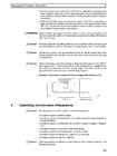
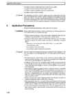
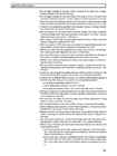
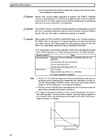
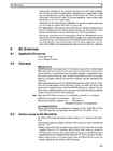
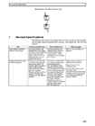
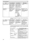

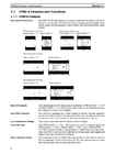
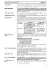
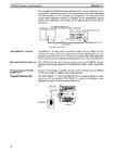
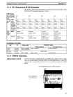
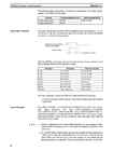
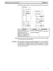
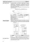
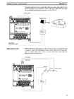
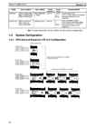
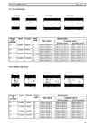
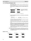
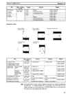
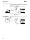
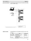
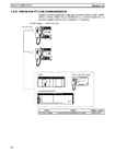
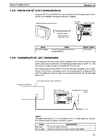
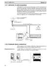
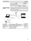
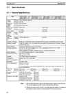
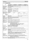
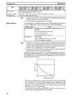
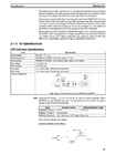
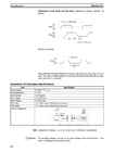
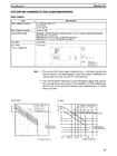
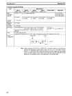
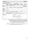
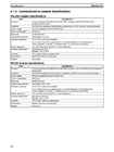
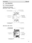
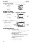
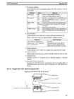
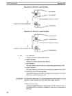
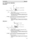
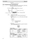
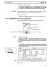
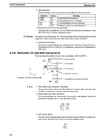
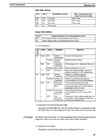
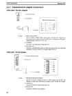
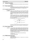
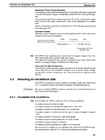
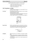
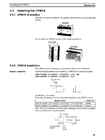
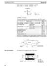
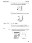
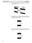
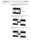
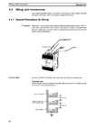
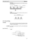
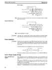
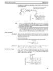
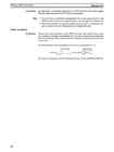
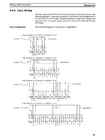
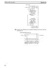
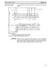
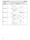
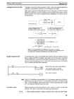
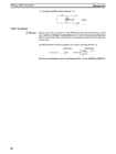
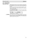
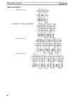
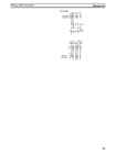
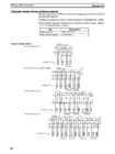
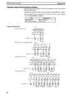
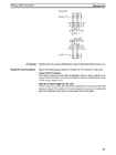
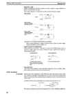
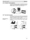
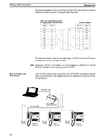
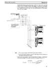
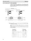
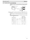
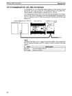
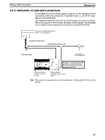
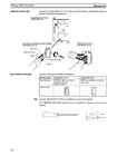
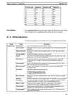
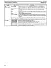
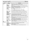
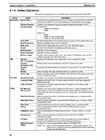
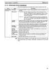
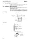
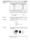

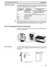
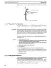
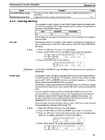
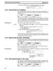
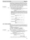
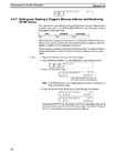
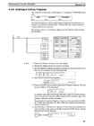
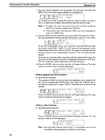
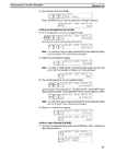
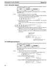
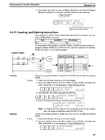
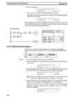
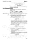
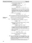
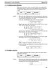
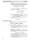
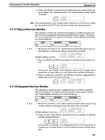
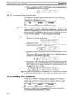
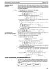
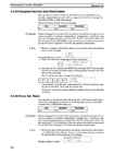
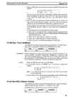
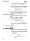
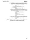
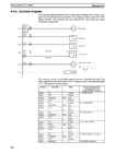
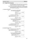
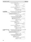
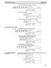
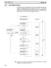
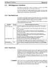
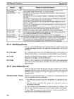
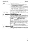
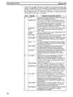
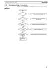
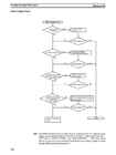
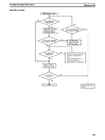
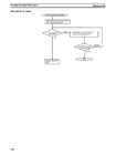
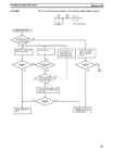
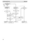
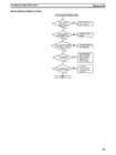
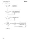
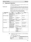
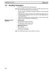
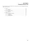
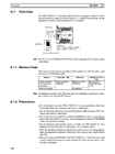
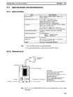
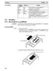
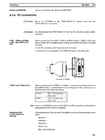
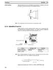
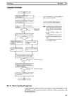
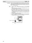
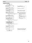
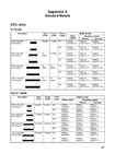
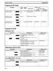
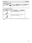
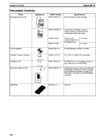
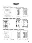
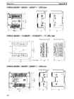
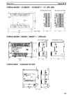
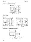
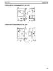
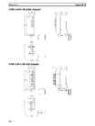
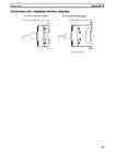
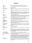
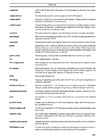
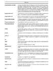
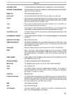
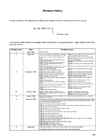
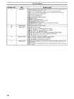


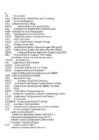
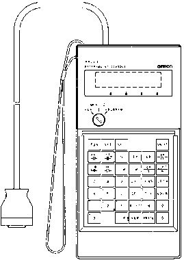
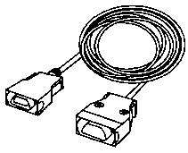
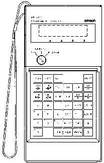
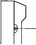


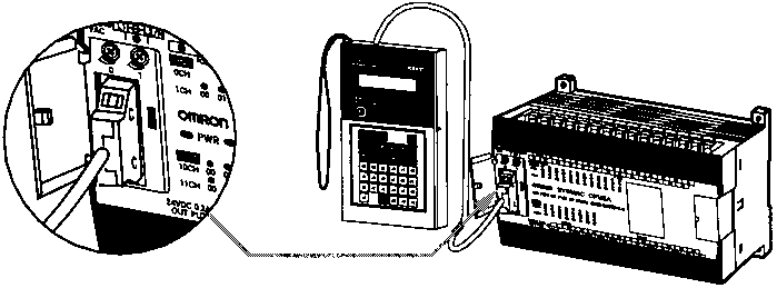
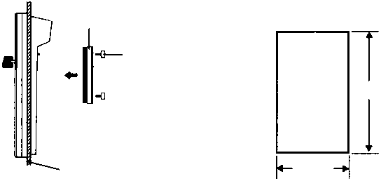
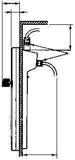

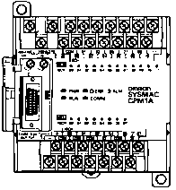

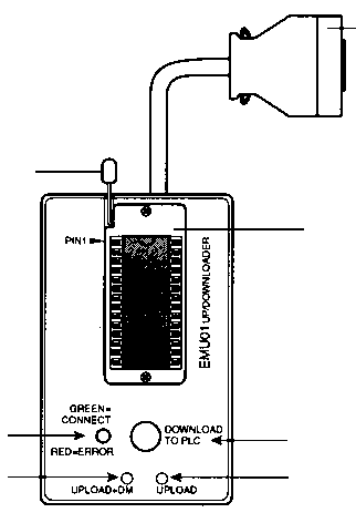
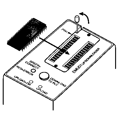
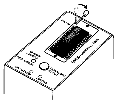
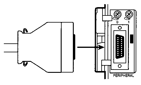
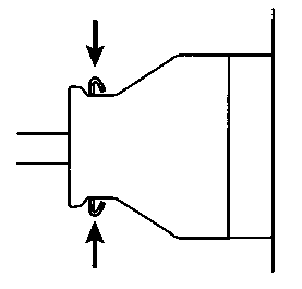


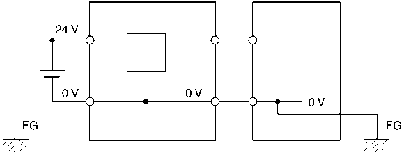


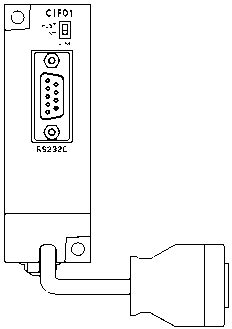


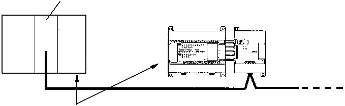
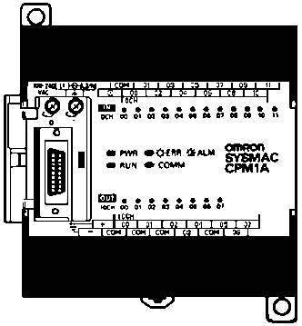
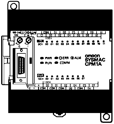
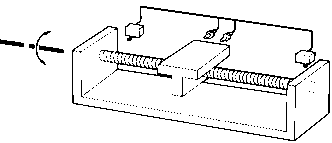


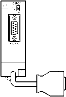
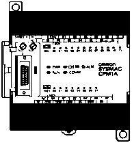


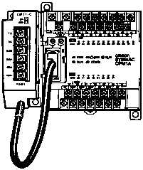


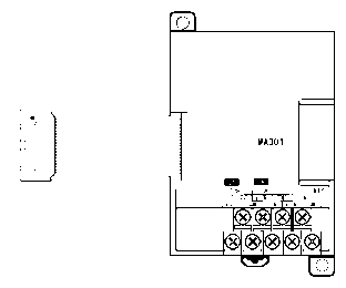
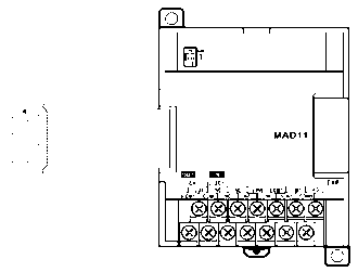


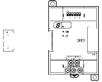
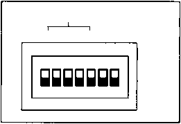
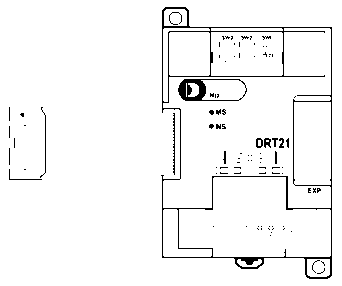
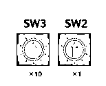


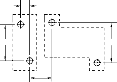
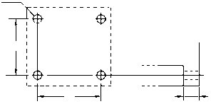
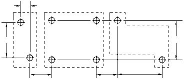


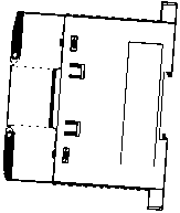


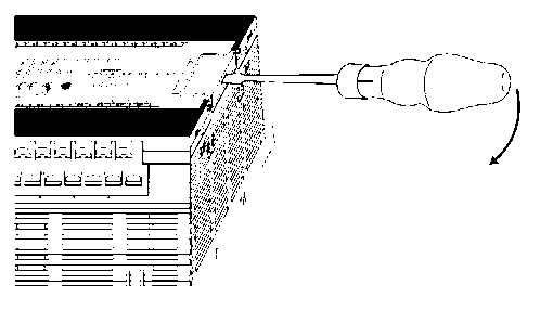
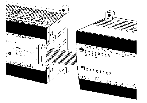
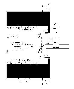
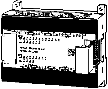
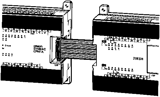
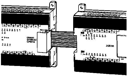
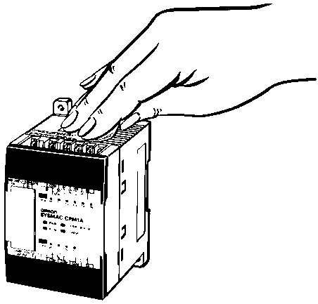
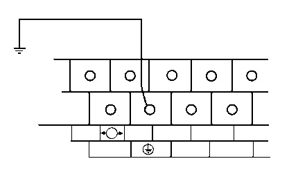
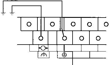
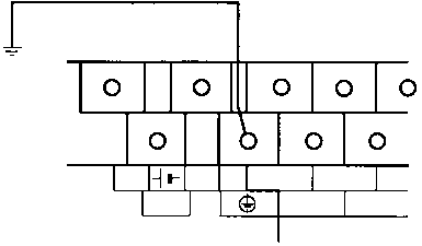

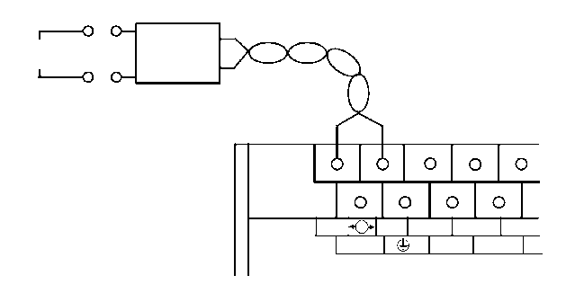


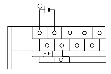


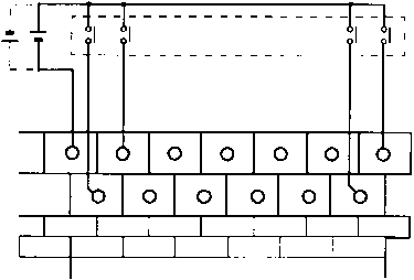
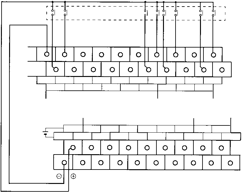
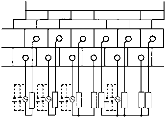
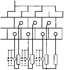
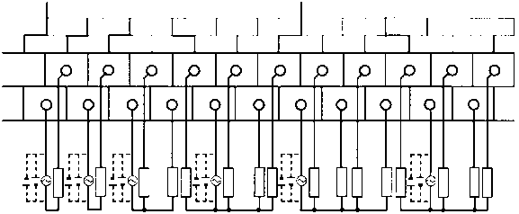


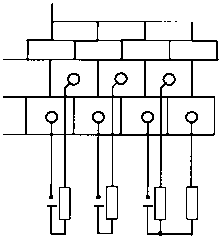
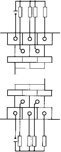
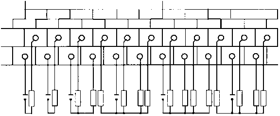
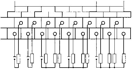
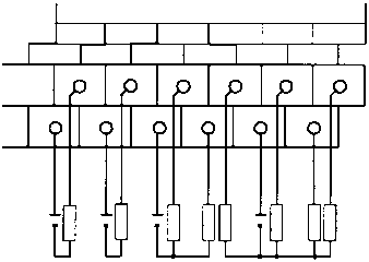


Kõik kommentaarid