oData transparency : In
bit and byte oriented protocols,
there is a problem if a
control character (for byte-oriented protocols) or the start-of-
frame flag
(for bit-oriented protocols)
appears in the actual data. This was not
likely to
happen in
ASCII text, but is very likely with
binary data.
This is
known as a
data
transparency problem
an can be rectified with
byte
stuffing (for
byte-oriented protocols) and
bit
stuffing (for
bit-oriented protocols).
> Byte stuffing (STX,
ETX, DLE) Transmit
side:
insert DLE
before control
characters 1. transmit start of frame –
send DLE STX 2.
prior to transmission insert DLE for any inadvertent
DLE 3. transmit end of file – send DLE ETX
Receive
side:
1. receive DLE STX -> indicates start of frame sequence 2. inspect
each byte in the payload
until EOF sequence. If byte(i) = DLE: – if
byte(i+1) = DLE -> indicates inadvertent DLE discard byte – if
byte(i+1) =ETX -> indicates end of frame
> Bit stuffing 1.
scheme:
flags
(often
used on point-point
links ) – flag =
01111110,
unique byte pattern for SOF & EOF – frame read on 8 bit
boundaries until EOF detected – reception
terminated.
- ensure flag pattern isn’t in frame data -> bit stuffing •
transmitter inserts
stuff bits :
if ‘11111’ detected -> insert ‘0’ – flag pattern can
never be
present in frame data – performed by transmit
circuit at
PISO output – disabled
during transmission of SOF, EOF •
receive
circuit:
if ‘
111110’
detected ->
remove
‘0’
– prior to input into SIPO – normally FCS data (prior EOF)
subjected to
same bit stuffing
O Asynchronous Transmission
Independent
transmit & receive
clocks . – receiver explicitly resynchronizes
on 1st bit of each byte – remaining bits recovered by
estimating
bit
boundaries – explicit byte synchronization become critical for
correct bit synchronization.
is
useful for: • data with
irregular arrival
times (human
input/output) • transmission line with long idle
states • used
when relatively
coarse synchronization is ok e.g.
terminal &
keyboard I/O Async. transmission is characterized by: • no
direct clock information
between receiver and transmitter • receiver has
to re-synchronize at each byte: uses additional bits –
bytes are
encapsulated in between start bit & stop bit. – bit
synchronization uses
start
bit &
stop
bit for
each byte. Internally , nodes
store ,
process , &
transfer data in
parallel Transmission control circuit -
interface between
node &
link : •
PISO
shift register : parallel->
serial conv. for transmission •
SIPO
shift
register: serial->parallel conv. for receiveing • bit,
character, frame synchronization • set data
rate , data
format •
error control:
generate /evaluate
check digits for error detection
> Bit synchronization
Independent
transmit & receive clocks.– receiver explicitly resynchronizes
on 1st bit of each
byte
–
remaining bits recovered by
estimating
bit
boundaries –
explicit byte synchronization become critical for
correct
bit synchronization. Receiver clock:
– used
to ‘clock’
incoming signal into SIPO register – runs
asynchronously with
respect to incoming signal –
local clock used
to sample signal near
center -> recover & shift bit into SIPO
– local clock = N·R, N = 16 is common 1. 1st signal transition
from 1-> 0 =
start
of byte (SOB)
2. Each signal sampled at ½ bit time – 1st signal sampled after
N/2 cycles – ith signal sampled after N/2 + N(i-1) cycles 3. Each
sample represents bit that is shifted into SIPO register
•
Effect of clock drift on bit synchronization Bit
synchronization is unreliable at
higher data-rates – detection of
bits are only an approximation – clock drift can
cause incorrect
sampling
instant .
> Byte synchronization
Bit
counting
used
to determine byte
boundary e.g. SOB, 8 bits, EOB – relatively
simple once bit correctly recovered. After
received , character
transferred into local
buffer – cpu notified that new character
received (interrupt or polling) – await next SOB (1 -> 0
transition) Receiver & Transmitter must operate with same
parameters – bits per character – number of stop-start bits –
signal rate
> Frame synchronization
Receiver
must identify SOF & EOF 1.
frames consist of
text
characters only
-> use non-text characters – STX & ETX: ASCII characters for
‘start of text’ & ‘end of text’ 2. frames are
pure binary data (no
restrictions) – inadvertent STX or ETX in payload can cause
incorrect
behavior .
> Xmodem, –
One of the oldest async file transfer protocols– Uses stop-and-
wait ARQ. – Advantages • Universally
available • Copes well with
noisy lines –
Disadvantages • Small packet
size = high overheads
= low efficiency • No batch facility
Ymodem, Zmodem, Zmodem:
– Newer
protocol than Xmodem – Incorporates
features of several
protocols – Uses CRC-32 with
continuous ARQ (sliding window) –
Dynamically adjusts packet size according to
communication circuit
conditions –
Usually Zmodem is preferred to Xmodem. – Advantages
• Large packet size = low overheads = high efficiency • Batch
Transfers • Auto receive – Disadvantages • Relatively
susceptible to noisy lines • Not available in all comms packages
Kermit:
– Supports
different packet data sizes and error detection methods
– Typically uses 1 KByte packets with CRC-24 • size adjusted
during transmission to optimize efficiency
o Synchronous Transmission
2
general
types character oriented & bit oriented –
both use same
bit synchronization – major
difference : byte & frame
synchronization – bit oriented synchronous transmissions is most
prevalent Distinguishing
synchronous
&
asynchronous
transmission:
– asynchronous has ‘start bit’ & ‘stop bit ’ –
asynchronous: receiver clock not synchronized with incoming signal –
synchronous: receiver clock synchronized to incoming
signal.
Global clock or synchronized transmit & received clocks – bits
are explicitly recovered – frame is transmitted as contiguous bit
stream – receiver synchronizes each bit for duration of frame. In
synchronous transmission,
greater efficiency is achieved by grouping
characters together, and doing
away without the start and stop bits
for each character. We
still envelop the information in a
similar way
as before, but this time we send more characters between the start
and end sequences. In
addition , the start and stop bits are replaced
with a new format that permits greater flexibility. A start type
sequence, called a header, prefixes each block of characters, and a
stop type sequence, called a
tail , suffixes each block of characters.
Synchronous tranmission uses explicit bit synchronization: •higher
bit rates, more efficient • Data is transmitted in large contigous
blocks of bits or characters. •
frame
= unit of transmission. •frame contains payload (data) and overhead
(control bits)
> Bit synchronization
bits
are encoded in signal transitions. • each frame transmitted as
contiguous bit stream • 2 ways receiver obtains & maintains bit
synchronization 1.
Clock
Encoding:
clock timing information embedded in transmitted signal extracted by
receiver 2.
DPLL
(
digital phase locked
loop ): uses forced signal bit transitions in signal –
receiver clock synchronized to signal by DPLL –
requires forced
signal transitions in signal (e.g. bit stuffing)
•
Clock Encoding and
extraction
Bipolar encoding:
uses RZ (
Return to
Zero ) signal • uses 3 signal levels:
+V,
0, -V
• ‘1’ encoded by ‘
+V’
signal • ‘0’ encoded by ‘
-V‘
signal • return to
0
after
each bit
Bit centre vs bit edge transition
Manchester encoding
or
phase
encoding:
uses
NRZ (Non Return to Zero) signal
•
always
center
bit
transition,
edge
transition
if needed
–
binary ‘
1’
->
lo-hi
center
transition
–
binary ‘
0’
->
hi-lo
center
transition
–
center bit transition used by receiver’s clock extraction circuit
to
produce clock pulse in center of 2nd
half of bit cell.
•
sampled signal is either high (1) or low (0) -> shifted into
SIPO
Differential Manchester encoding •always
center bit transition for clock synchronization •
edge
transition at
start of next bit only if next bit = ‘0’ •encoded output
takes on 1 of 2
forms , depending on initial state – either is an
inverted form of the
other – clock generated at end of each bit cell –
edge
transition determines
if bit cell is ‘0’ or ‘1’
Manchester
Schemes are balanced codes:• no
mean DC
value •
000…
or
111…
always has transitions (no constant DC signal) •
important for AC
coupling to receiver using transformer •isolates receive
electronics power
supply from transmitted signal
•
DPLL (digital
phase locked loop) •
Alternative
to
clock encoding for bit synchronization •Requires a sufficient edge
transitions in bit stream – receiver resynchronize’s clock with
edge transition – scramble input data or
NRZI with bit stuffing
•Estimates bit timing in between edge transitions
Pass data
through scrambler
before
transmission – randomize bit stream -> remove contiguous 1’s &
0’s – unscramble at receiver using inverse
operation . DPLL
circuit: • used to
maintain bit synchronism • DPLL clock
frequency ≈ 32 · bit rate • must
hold frequency sufficiently
constant –
require only small adjustments at irregular intervals.
DPLL uses clock to derive timing interval to sample incoming bits –
assumes bit stream & local clock are
synchronized
– input signal state (‘1’ or ‘0’) sampled at center of each
bit – signal clocked onto SIPO register – exactly 32 clock
periods between each sample.
NRZI encoding
(non-return
to zero, inverted)
•
signal level changes for ‘0’ doesn’t
change for ‘1’
–
‘111…’
results in no transitions
–
‘000…’ results in n transitions
-
differential encoding
‘
0‘
insertion bit used
for every 5th
‘1’
bit
-guaranteed number of transitions enables receiver to
adjust clock to
synchronize with bit stream
Bit
synchronization(sampling instant adjustment)Assume
only small clock variations • cause incoming bit stream & clock
to
drift
out of
synchronization
•
adjust
sampling instants in
discrete increments 1. no bit transition -> DPLL generates
sampling pulse at 32 ticks 2. if bit transition detected (
at least every 5th bit):
– determine
drift amount =
actual signal transition relative to last – DPLL sample:
drift
=
tactual_transition - (tsample + N/2)
– adjust time to next sampling pulse depending on amount of drift.
•
Baud rate vs bit
rate> Byte
synchronization: hunt mode> Character
oriented synchronous transmission• Differences with
asynchronous transmission •
used primarily for transmission of blocks of characters (
ASCII
files)
• no ‘start’ & ‘stop’ bits -> uses transmission
controlcharacters before each block • known as
SYN
(synchronous
idle) characters –
1st
SYN allow receiver to obtain & maintain
bit
synchronization
–
2nd
SYN provides
byte
synchronization
–
Frame
Synchronization ~
Asynchronous Transmission using STX & ETX
1.
obtain
bit
synchronization with
1st SYN – starts receiving bits 2. enter hunt mode for
byte
synchronization:
after each bit -> check last 8 bits 3. frame synchronization:
process each byte
looking for STX - after STX, read frame contents
look for ETX – after ETX, transmitter can maintain synch by sending
SYNs, otherwise receiver has to
repeat hunt mode with new frame –
data
transparency:
same as with asynchronous (DLE)
– inefficiency:
additional control characters: STX,ETX, DLE, SYN
•
Binary synchronous
protocol: PAD, SYN, STX, ETX, …
Every package that is transmitted is packed between an STX and an ETX
character, followed by one (LRC-check) or two (CRC-check) BCCs (Block
Check Character). After this (and the check on the receiving side)
the receiver will send an ACK.SYN (Synchronous Idle) •Provides the
hardware recognizable bit pattern rquired to establish character
synchronization at the receiving
adapter .
ENQ
(
Enquiry )
•Recognized as a request for a response, or a bid for line control. In some cases it may be used to signify an abnormal end of
text or
message '
abort '.
SOH
(Start of Header) •Indicates the inclusion of auxiliary data
preceding the message text.
STX
(Start of Text) •Indicates the
beginning of data in a block. STX
may be preceded by a header. Directly behind the STX is the
first character of the data
field .
NAK
(
Negative Acknowledgement) •Indicates that there was an error in a
data block. Also used as a response to a bid for line control to
indicate a 'Not
Ready '
condition .
DLE
(Data Link
Escape ) •Multiple
usage as a control character modifier.
ETB
(End of Transmission Block) •Indicates an end of data block, but
more will
follow . Is used to instruct the receiving unit to
perform error checking and acknowledge.
ETX
(End of Text) •Same as ETB, only no more blocks will follow.
ITB
(End of
Intermediate Transmission Block) •Same as ETB, except that
the receiving statio will not acknowledge after the error checking.
EOT
(End of Transmission) •Indicates that a
station has no data to
transmit.
>Bit oriented synchronous
transmission:
preferred
scheme • transparent to either printable characters or binary data
• 3 general schemes that vary on how SOF, EOF is signaled •received
stream searched on bit
basis for SOF & EOF • frame
divided into
fields that are often multiples of 8 bits 1. scheme:
flags
(often
used on point-point links) – flag =
01111110,
unique byte pattern for SOF & EOF – frame read on 8 bit
boundaries until EOF detected – reception terminated.
2.
scheme:
SOF delimiter &
length indicator i) receiver searches for
SOF
delimiter ‘01111110’
ii)
fixed header follows with
address
& length of
data iii) receiver
counts
number
of bytes to determine EOF • used in LANs (
broadcast transmission
media) – node’s
destination
address precedes
user data (
payload)
–
clock
synchronization achieved
when sender transmits
preamble
– allows other nodes to obtain bit synchronization.
3.
scheme:
bit-encoding
violations (
also used w/ LANs) • 1.5 bit manchester (3 signal pulses) -> no
transition in 1st bit • no signal transition ->
illegal manchester
code –
J:
signal level remains same as
previous for 1 bit
period –
K:
signal level remains opposite as previous for 1 bit period – frame
payload can’t
contain J,K
symbols
•
Frame
synchronization schemes:•
Data Link Control
ProtocolsoHDLC Within HDLC, there are three types of stations defined:1.
Primary Station - this
completely controls all data link operations issuing
commands and receiving
responses from secondary stations. It has the
ability to hold separate sessions with different stations(on
multipoint line) 2. Secondary Station - can only communicate with the
primary
station. Secondary stations only talk to each other via a Primary
station: receive command frames from Primary, transmit response
frames to Primary. 3. Combined Station – has the combined
functionalities/ responsibilities of both primary and secondary
station.
> Operation of
combined station •
Contains protocol
components of primary and secondary in one
physical station. • Transmits both commands and responses.
• Receives
both commands and responses. • Uses line addresses to distinguish
between command and response frames: – Frame received with own
address -> command – Frame received with partner address ->
response – Frame transmitted with own address -> response –
Frame transmitted with partner address -> command
> Balanced vs Unbalanced configuration Configuring
a
channel for use by a 1. Unbalanced configuration -
consists of a
primary station
and
one or more secondary stations. Primary is
responsible for
controlling all secondary stations In unbalanced configurations, any
of the
following can be
used:
full duplex or half duplex operation, point to point or
multi-point
links.2. Balanced configuration - consists of two combined
stations(peers). Stations have equal responsibility for error
recovery and line
management . Balanced configuration is used only
with point to point
links,
which can be half duplex or full duplex.
> Operation modes :• Normal Response Mode (NRM):
– the
primary station always initiates transfers to the
secondary
station.– the secondary station must receive explicit
permissionfrom the primary station to transfer a response.– after
receiving
permission from the primary station, thesecondary station
initiates it's transmission.
– this
transmission from the secondary to the primarymay be much more than
just an ack of a frame.– it may in
fact be more than one
information frame.
– once
the last frame is transmitted by the secondarystation, it must wait
once
again for explicit permissionfrom the primary station, to
transfer anything.
•
Asynchronous
Response Mode
(ARM):– the secondary does not have to wait to receive
explicitpermission from the primary to transfer any frames.
– the
frames may be more than just acknowledgmentframes. They may contain
data, or control informationregarding the
status of the secondary
station.
– this
mode can
reduce overhead on the link, as noframes need to be
transferred in
order to give thesecondary station permission to
initiate a transfer.
– on
multipoint lines, only one secondary can be in ARMmode.
– the
primary station still retains responsibility for errorrecovery, link
setup, and link disconnection.
• Asynchronous Balanced Mode
(ABM):
– this
mode uses combined stations.– there is no need for permission on
the
part of either station in this mode.– this is because combined
stations do not require any
sort
of instructions to perform any
task on the link.– both stations are
equally responsible for error recovery and can establish or clear a
connection .
– this
is the most common mode used on P-to-P links.
> Non operational Modes
HDLC also defines three non-operational modes.
These are:
1.
Normal Disconnected Mode(NDM) – for unbalanced mode
– secondary
not ready to receive any I or S frame
2.
Asynchronous Disconnected Mode(ADM) – for unbalanced mode
– combined
station not ready to receive any I or S frame 3. Initialization
Mode(IM)
– used
for initialization of stations (download of software) or
exchange of
parameters between stations. The two disconnected modes (NDM and ADM)
differ from the operational modes in that the secondary station is
logically
disconnected
from the link (
note the secondary station is not physically
disconnected from the link). The IM mode is different from the
operations modes in that the secondary station's data link control
program is in need of
regeneration
or it is in need of an exchange of parameters to be used in an
operational mode.
> Principle Frame types: Information vs Supervisory vs
Unnumbered
There are three control field formats and
hence three principle
frame
types:
1.
Information format - I frame
“I” frames are used for the data transfer between stations. The
send sequence, or next send
N(S),
and the receive sequence, or next receive
N(R),
hold the frame sequence
numbers .
The
Poll / Final bit - for
unbalanced link
access control: – when the primary
sends something
with the P/F bit turned on, it's a poll to the secondary (gives that
station access to the line) – secondary transmits with P/F bit off.
– when secondary station
done transmitting, it turns the P/F bit
back on, indicating that it is
finished (Final bit).
2.
Supervisory format - S frame”S”
frames are used for error control (to acknowledge frames or
request
for retransmissions) or flow control (to ask for
suspension of transmission).
The
Supervisory code denotes the type of supervisory frame
being
sent . Supervisory codes(used for both Command and Response):
– 00:
Receiver Ready (RR)– 01: Reject (REJ)
– 10:
Receiver not Ready (RNR)– 11: Selective Reject (SREJ)
3.
Unnumbered format - U frameUnnumbered
Commands(uncomplete):
• Set
Normal Response Mode (SNRM)• Set Async Response Mode (SARM)
• Set
Async Balanced Mode (SABM)• Unnumbered Information (UI)
• Exchange
Identification (XID)• Disconnect (
DISC )
”U”
Frames are used for link initialisation or link disconnection.
The
Unnumbered bits indicate the type of Unnumbered frame
being
used.Unnumbered Responses(uncomplete)
• Unnumbered
Acknowledge(UA)• Frame Reject (FRMR)
• Request
Disconnect (RD)• Unnumbered Information (UI)
• Exchange
Identification (XID)• Disconnect Mode (DM)
> Special bit
sequences–
Flag field: 01111110 (7E hex)– Abort sequence: at least 7, but
fewer than 15
Ones • when Abort received, the stations on the link
know there
is a problem on the link– Idle sequence: 15 or more OnesMost
synchronous links constantly transmit data:– during the
inter -frame
period, these links can transmitall 1s (mark idle), or all flag
characters (flag idle).HDLC is code transparent:– uses bit stuffing
(zero insertion) if flag sequence would
appear
within frame
Information transfer format
command and response• The
functions of the
Information command
and response(C/R) frames are to transfer sequentially numbered
frames(each containing an information field)
across the data link.–
Requires connection setup prior to data transfer
Supervisory format commands
and responses•
Supervisory(S) commands and responses are used toperform numbered
supervisory functions
such as
acknowledgment, polling,
temporary suspension ofinformation transfer, or error recovery.•
Frames with the S format control field cannot contain an
information field.
Supervisory format commands and responses•
A primary station may use the S format command framewith the P bit
set to 1 to request a response from asecondary station regarding its
status.• Supervisory format commands (C) and responses (R) are
asfollows:–
Receive
Ready(RR) (C/R) is
used by the primary orsecondary station to indicate that it is ready
to receive
an information frame and/or
acknowledge previously received frames.
–
Receive Not Ready(RNR)
(C/R) is used to
indicate that the primary or secondary station is not ready to
receive any information frames or acknowledgments. –
Reject(REJ)
(C/R) is used to
request the retransmission of frames.–
Selective
Reject(SREJ) (C/R)
is used by a station torequest retransmission of
specific frames.
Unnumbered Format commands
and responses• The U format commands and
responses are used to extendthe number of data link control
functions.• The U format frames have 5 modifier bits which allow
for
up to 32 additional commands
and 32 additional responsefunctions.•
Below , 13command (C)
functions, and 8 response (R)functions are
described .–
Set
NormalResponse Mode(SNRM) (C)
places thesecondary station into NRM.
NRM does not allow the
secondary station to send anyunsolicited frames.Hence the primary
station has control of the link.–
Set
Asynchronous Response Mode(SARM) (C)
allows asecondary station to transmit frames without a pollfrom the
primary station.–
Set
Asynchronous Balanced Mode(SABM) (C)
sets theoperational mode of the link to ABM.–
Disconnect(DISC)
(C) places the
secondary station into a disconnected mode.–
Set
Normal Response Mode Extended (SNRME) (C)
increases the size of the
control field to 2 octets instead
of one in NRM. This is used for
extended sequencing. –
Disconnected
Mode(DM)(R) is
transmitted from asecondary station to indicate it is in
disconnectedmode(non-operational mode.)–
Request
Initialization Mode(RIM) (R)
is a request froma secondary station for initialization to a
primarystation. Once the secondary station sends RIM, it canonly
respond to SIM, DISC, TEST or XID commands.–
Request
Disconnect(RD) (R)
is sent by the secondarystation to inform the primary station that it
wishes todisconnect from the link and go into a
non-operationalmode(NDM or ADM).–
Frame
Reject(FRMR) (R) is
used by the secondarystation in an operation mode to
report that a
conditionhas occurred in transmission of a frame andretransmission of
the frame will not correct the
condition.
> NRM operation and error recovery> ABM operation and error
recoveryoDLC service modes:> Connection–oriented vs
connectionless1. Reliable/
virtual -circuit
(
connection-oriented
mode) ––
users establish connection before sending information packets– errors
dealt with using ACKs, NACKS2.
Best -try/datagram (
connectionless
mode)– frames in
error are just discarded (unacknowledgedservice)
> HDLC service modes
implementation HDLC
can
provide connection-oriented
service:• Setup of
connection done by U-frames– SNRM, SARM, SABM, UA• I-frames and
S-frames can be used only after connection setup– I, RR, RNR, REJ,
SREJ• Clearing of a connection done by U-frames– DISC, UA HDLC
can provide
connectionless
service:• Only
U-frames can be used– UI for data transport
o LLC•
Used with Local Area
Networks (LANs)• Defined in IEEE 802.2
specification• LANs have two sublayers in Data Link
Layer (LLC and
MAC),– LLC is at higher level
than MAC
– will
discuss MAC
later .
(MAC =
Medium Access Control)
• LLC is
required by many
IEEE 802 MAC protocols,
since they don’t provide a
multiplexing identifier to identify the
higher layer protocols.
• LLC is a
peer -to-peer
protocol (since MAC takes care of
access to
network we do not
need primary/secondary
relationship)
> Differences with
HDLCDiffers from HDLC because of
multiaccess MAC that provides
framing/error detection:
– Has 2 address fields
(source & destination) for multiaccess
– Lacks framing delimiters
and CRC
• Byte oriented (bit
orientation is rarely useful, and MAC
layers provide byte oriented
service)
– Sequence numbers
grow from
3b to 7b
• Control field for
unnumbered frames (lacking sequence
numbers) is shorter than for
information/supervisory
frames
> Functionality of
SAP and SNAP • MAC
address identifies a hardware interface (“station”). • LLC
Service Access Point identifies a protocol
within the
device having that
hardware interface.
SAPs are 7b: shortage ->
SNAP above LLC
– Typical network protocol
evolution : • extend one protocol by tacking on parts (in this
caseanother protocol)
The DSAP, or
Destination
Service Access Point,
is a 1 byte
field that simply
acts as a
pointer to a memory buffer in the
receiving station. It tells the
receiving NIC in which buffer
to put this information.
The SSAP, or
Source
Service Access Point is
analogous to
the DSAP, and specifies the
Service Access Point (SAP) of
the sending process.
In order to specify that this
is a SNAP frame, the DSAP/SSAP
is set to AA hex.
The Sub-Network Access
Protocol (SNAP)
field: 5 bytes
LLC Service types compared
to HDLC service modesWhat's new in
the frame, compared to HDLC:
• Two octet address (first is
destination, second is source):
– these are LLC addresses and
NOT addresses that appear on
the network medium!
• No FCS (assumes MAC layer
will
handle it, so why bother!)
• For connection-oriented
service, unlike HDLC:
– must operate in SABME mode;
no SNRM, SNRME, or
SABM modes.
– No selective reject
• For acknowledged
connectionless service:
– AC (C/R): Acknowledged
Connectionless: permits
unnumbered stop-and-wait
transmission (in addition to
HDLC’s sliding window)
(C=data,R=ack)
LLC Can provide 3 types of
service to higher layers:
•
Connectionless,
either
–
Unacknowledged (“Type
1”), or
–
Acknowledged (“Type
3”). 2 forms:
•
Push : source initiates
transfer and receives ack
•
Pull : destination initiates
transfer and receives data
(Service
primitives at
interface to higher layer:
–
REPLY .request to poll–
REPLY.indication when response comes– REPLY-UPDATE for higher layer
to
feed data into
LLC for responding to polls)
Unacknowledged connectionless
(“Type 1”) is similar to UDP.
Acknowledged connectionless
(“Type 3”) provides acks, but
doesn’t provide error
recovery, sequencing or flow control.
•
Connection-oriented
(“Type 2”) mode
is similar to TCP.
– Only supports unicast
connections
– Primitives to manage
established connections:
• DISCONNECT a connection
(i.e. terminate it)
•
RESET a connection (i.e.
reinitialise, possibly losing
data – up to higher layers to
recover)
logical connection must be
established using L_CONNECT
prior to data transfer
• after all data transfer,
connection must be cleared using
L_DISCONNECT
• during data transfer all
error free data units are acknowledged
• L_RESET abort, any
unacknowledged frames are discarded
• L_FLOWCONTROL specifies the
amount of data the user is
prepared to accept
Priority can be specified for
all
services .
– This is always
passed to
the MAC layer to prioritise access
(if supported).
– For connection-oriented
service, it also prioritises use of
LLC resources
• All nodes must
support the
unacknowledged connectionless
service (common in
Ethernet 802.3), whereas support of the
other services is optional.
> Operation of
LLCLLC uses
underlying MAC layer to communicate with endpointby
passing parameters specifying network address and all thedata.a) local
confirm: whether request has been successfully transmittedb) remote
confirm: whether request has been successfully received
oPPP> Importance ,
Application areas , Protocol stacksOne sender, one receiver, one
link - easier than broadcast link:
– no Medium Access
Control(MAC)
– no need for explicit MAC
addressing
– e.g., dialup link,
ISDN line, DSL line
Hence, it’s called the
Point-to-Point Protocol (PPP)
Why is PPP important:
•
multiplex multiple
protocols over a
single serial connection
• handle compression and
encryption at lowest possible layer
•
easy authentication at
other end of connection
Two precise definitions of
"point-to-point" in the
context of
data communications follow:
1. A network configuration in
which a connection is
established between two, and
only two
points .
The connection may
include switching
facilities .
2. A circuit
connecting two
points without the use of any
intermediate terminal or
computer.
These definitions
explain the
point-to-point aspect of PPP.
The protocol aspect
lies in the
fact that PPP is the intermediate
packet structure which
facilitates transmission of higher
level protocols, such as
TCP/IP, across diverse
communication links.
Application areas•
Designed to be used when
the
carrier provides bit transfer,
not frame transfer, e.g.:
– Routers connected by leased
lines
– Home user to ISP over phone
line
• Includes specs for how to
test the physical channel
-> PPP over Sonet
[RFC(Request for Comments) 2615], etc
• So
popular , than often
layered on top of protocols that
provide frame transfer so that
these protocols can be
accessed by higher layers built
to use PPP!:
– PPP over AAL5 (ATM Adaption
Layer) [RFC 2364]
– PPP over Ethernet (PPPoE)
[RFC 2516]: discussed later
> Design requirements and non requirements•
packet framing:
encapsulation of network layer datagram
in data link frame
–
carry network layer data of
any network layer protocol
(not just IP) at
same
time– ability to demultiplex
upwards(multiple protocol support)
•
bit transparency:
must carry any bit pattern in the data
field
•
error detection (
no correction )
•
connection liveness:
detect link
failure and signal status
change to network layer
•
network layer address
negotiation:
endpoints can
learn/configure each other’s
network address
• no
prevention of long runs
of certain bit
strings • no error
correction/recovery
• no flow control
• no need to support
multipoint links (e.g., polling)
Error recovery, flow control,
data re-ordering(sequencing):
– all delegated to higher
layers!
> PPP Frame format
compared to HDLCPPP is character-oriented
version of HDLC.
It uses similar frame structure
as HDLC, except:
•
Flag:
same flag as HDLC, but uses byte stuffing.
•
Address & Control
fields: legacy of
the HDLC frame
format.
– Address field value “FF”
= broadcast,
– Control field value “11”
= UI (Unnumbered Information)
An option allows the omission
of the A and C fields.
• Payload(
info)
field contains an integer number of bytes.
New field in PPP, compared to
HDLC:
•
Protocol type field:
indicates, which higher layer protocol
should this frame be delivered
to.
e.g. IP, IPX, PPP control
protocol(LCP or NCP)
– Link Control Protocol
(LCP): bringing up, testing,
bringing down lines;
negotiating options.
– Network Control Protocol
(NCP): to configure upper
layer protocol, e.g. IP Control
Protocol(
IPCP )
> PPP version of
byte stuffingDue to the
nature of PPP byte
stuffing, a problem can appear:
– Size of PPP frame can grow
unpredictably due to byte
insertion.
Problem appears only if the
maximum size of frame is limited.
Example of PPP byte stuffing:
Flag=0x7E (01111110), Control
escape=0x7D (01111101)
Any occurrence of flag or
control escape inside of frame is
replaced with 0x7D, followed by
original octet XORed
with
0x20 (00100000):
The three major components
of PPP:1. A method for encapsulating
datagrams over serial links –
framing and transmitting
frames.
2. An extensible Link Control
Protocol(LCP), to establish,
test, configure, and tear down
a link.
3. A family of Network Control
Protocols(NCPs) for
establishing and configuring
different network layer
protocols.
•
Framing and
transmission•
Link Control
Protocol(LCP)
Link configuration,
Configuration options
negotiated using LCP:
• Header compression:
–
omit fields that
aren ’t
used (to save bandwidth over
slow lines), e.g. omit Address
& Control fields.
– length of protocol field
(1B or 2B)
• Maximum payload length
(default: 1500)
• Type of CRC (2B or 4B)
• Disable or
select authentication stage (PAP,
CHAP , EAP)
• Line
quality monitoring
during normal operation (the
ability to verify whether the
line has a
good enough quality
to reliably support the
connection).
link termination Using
LCP, PPP can terminate the link at anytime.
This might happen because of:
– the loss of carrier,
– authentication failure,
– link quality failure,
– the expiration of an
idle-period
timer ,
– or the administrative
closing of the link.
LCP Frame types•
Network Control
Protocols(NCPs)
Functionalities,
message types Authentication phase: Link
establishment (LCP) can be followed by optionalauthentication phase
before proceeding to network layerprotocol (NCP) phase.
•
Auth . protocolsVarious protocols for
authentication:
– PAP(Password Authentication
Protocol): password sent in clear;
no playback
protection ->
PAP should be avoided!
– CHAP(
Challenge Handshake
Authentication Protocol): encrypted password
but the pwd must be stored as
cleartext on the
server .
EAP(Extensible Authentication
Protocol) – most flexible, best choise.
•
Why auth. at link
layer?• Client doesn’t need
network access to authenticate
– No need to
resolve names ,
obtain an IP address prior to
auth• In a multi-protocol
world, doing auth at link layer enablesauthorizing all protocols at
the same time– Doing it at the network layer would mean
adding authentication within
IPv4 ,
IPv6 , AppleTalk, IPX,
SNA, NetBEUI• Would also mean
authorizing within multiple layers•
Result : more
delay > PPP operationAfter the LCP
component of PPP
establishes the link, then the
NCP component will negotiate
the network layer protocol
that PPP actually encapsulates
and transports.
For example, if the PPP link is
configured to connect with IP,
then the
Internet Protocol
Control Protocol (IPCP) will
negotiate and configure the
link to carry IP.
An NCP, such as IPCP, may
close the link over the network
layer protocol, and yet the PPP
connection can
remain open.
But if LCP closes the link,
then all communication layers
terminate,
including the
network layer, NCP fraffic, and the
PPP connection itself.
> PPPoE
PPPoE (defined in [RFC2516]) is a method to transport PPP packets
over Ethernet segments.
Since PPP was designed to do
things that were either impossible or unnecessary with Ethernet,
users are often
confused as to why one would
want to use PPP over Ethernet at all.
•
When is it useful?Compare TCP/IP
traffic to
vehicle traffic:
–
Basic TCP/IP protocol would
be comparable to a
network of city streets.
– Streets can
serve many
access points.
– It is easy to get on to and
off of the
street .
– Additional access points
can be added with
little disruption.
– It is hard to
tell how many
cars are actually using each street.
PPP, on the other
hand , would
be comparable to a railway
– Travel is generally between
two well defined points.
– You can't get on and off
anywhere.
– It is relatively easy to
count and
monitor passengers.
- You need a ticket to board .
If the previous is true, then
isn't PPPoE like
running railway
tracks down main street?
In fact, yes, it is.
– That is what tramways do.
– Without disturbing main
street traffic, they bring the
advantages of railways.
– They
offer speedy access
between two well defined
points and allow you to count
passengers.
- And you need a ticket to board.
PPP over Ethernet brings this
sort of functionality to ISPs that
do not use serial links to
connect their users.
Serial ISPs use PPP over modem
communications.
DSL providers on the other hand
use Ethernet, not serial
communications.
Because of this, many require
the added functionality of PPP
over Ethernet, which allows
them to:
– secure communications
through the use of user logins
– have the ability to
measure the
volume of traffic each
•
Frame formatAn important restriction: 1492
Octets is the maximum number
of octets in the PPP payload
and Padding fields:
1492 Octets PPP payload &
PPP Padding + 2 octets PPP–ID +
6 octets PPPoE header yield a
maximum Ethernet V2.0
payload of 1500 octets.
•
Protocol
architecture•
Multiple AccessMultiple
nodes may
share a transmission channel.
• This
mode of operation is used for
wireless networks, and
was
common for
wired LANs before advent of switches.
• Nodes
are often called “stations” in this context
Sometimes
“
terminals ” (particularly for WANs) or “
devices ”
• Channel
called broadcast or multiple access
• Two
or more simultaneous transmissions by nodes ->
interference,
from “contention”/“
collisions ”.
– only
one station can send
successfully
at
a time
o Types of linksNeed
to coordinate transmissions to limit interference.
Analogy
with human meetigs:
Audio channel is shared.
•
Face -to-face:
Use
visual channel for control (e.g. raise hand,
eye
contact, rank, etc).
• Audio
conference: Coordination is less effective.
CB
radio “Over” & “Over and out”
Multiple
Access protocol(=Medium
Access Control protocol):
– algorithm
that determines how stations share channel,i.e., determine when
station can transmit.– note that communication about channel
sharing must usethe channel itself!What to look for in multiple
access protocols:– synchronous or asynchronous– information
needed about other stations– robustness (e.g., to channel errors)–
performanceClaim: humans use multiple access protocols all the
time!Design
goals for MAC protocol :efficient,
fair , decentralized,
simple, scalable,priority-dependent, deterministic
oMultiple access protocol:
main propertiesoIdeal MAC protocol propertiesBroadcast
channel of rate R bps:•
Efficient:
when
one node wants to transmit, it can send at
rate
R.•
Fair:
when
M nodes want to transmit, each can send ataverage rate R/M
• Fully
decentralized:–
no special node to coordinate transmissions– no synchronization of
clocks, slots•
Simple•
Scalable:
large number of nodes; large bandwidth-delayproduct (geographical
scope)
• Able
to
prioritize
traffic,
and provide delay bounds
oMessage priority: Local vs
Global priorityLocal
priority:•
each node can transmit its
highest priority message when itgets a
turn on the bus
Global
priority: which
node
gets the next turn on the bus?•
could be a organized as
round -robin selection of nodes• could be a
function of the node’s
inherent(static) priority• could be a function of the highest
priority message on eachnode – a “global message priority”
scheme
Fundamental tension:• reducing
latency for
high-priority nodes/messages, vs.• ensuring
global
fairness:
no starvation for low-prioritynodes/message
o3 broad classes of MAC
protocols:MAC
protocols can be divided into three broad classes:1. Channel
Partitioning (fixed assignment, multiplexing)– divide channel into
smaller “pieces” (time slots,
frequency,
code)– allocate
piece to node for exclusive use –
no
collisions2.
Random Access (contention, “transmit and
hope ”)–
allow
collisions,–
“recover” from collisions3. Handshaking (scheduling,
reservation-
based )– tightly coordinate shared access to
avoid
collisions–
for coordination, uses polling or
token passing
> Channel
Partitioning MAC protocols•
Partitioning
techniquesTechniques:•
“pieces” (
x)
= Time slots, Frequency(Wavelength), Code
• “
x
Division Multiplexing (
xDM)”:
Different flows ofinformation use different pieces of the channel,
e.g. TDM,FDM, Orthogonal FDM, etc• ´“
x
Division
Duplexing (
xDD)”:
Duplex communication is
achieved
by 2 ends using different pieces of the channel(typically time (TDD)
or frequency (FDD))
• “
x
Division
Multiple Access (
xDMA)”:
When multiplenodes are directly transmitting on a channel, e.g.
TDMA ,FDMA,
CDMA •
Issue : Contention
at the receiverIssues:•
Contention at the
receiver:Division
may resolve contention for the medium, but whatabout contention for
the receiver?e.g. multiple FDM
sources transmitting simultaneously
toone receiver that can only tune into one frequency at a time.
• TDMA: cycle TDM
(Time Division Multiplexing):channel divided into N time slots, one
per user;
inefficient
with low
duty cycle users and at
light load .TDMA: time division
multiple access
• access
to channel in "rounds"• each station gets fixed length
slot (length = pkt trans time)
in
each round• unused slots go idle• example: 6-station LAN, 1,3,4
have pkt, slots 2,5,6 idleBetter to think of this as a “cycle”.
While it is often called a “frame”, it is different from the
“frames”
that we have
considered , which are essentially linklayer versions of
packets.Only one station transmits any
particular “frame” (as
we’veconsidered), whereas multiple stations transmit in one of
these
“frames” (cycles).
•
FDMA: frequency
bandFDM
(Frequency Division Multiplexing): frequency subdivided.FDMA:
frequency division multiple access• Channel spectrum divided into
frequency bands• Each station assigned fixed frequency band•
Unused transmission time in frequency bands go idle
•
Combined TDMA &
FDMAOften
combined in practice, for example, in cellular phonenetworks:• TDMA
cellular
phones :– use 30 KHz
channels , with each channel divided
intothree time slots.– a single handset uses one timeslot for
sending and theother for receiving.• GSM uses 200 KHz
channelsdivided into eight time slots.A single handset uses one
slotin two channels for sending
and
receiving.
•
CDMA: encoding and
decodingCDMA:
code division multiple access• unique “code” assigned to each
user; ie, code set partitioning• used mostly in wireless broadcast
channels (cellular,
satellite,
etc)• all users share same frequency, but each user has
own“chipping” sequence (ie, code) to encode data–
encoded
signal =
(original data) X (chipping sequence)–
decoding:
inner-product (summation of bit-by-bitproduct) of encoded signal and
chipping sequence.• allows multiple users to “coexist” and
transmitsimultaneously with
minimal interference (if codes
are“orthogonal”)
•
TradeoffsAdvantages
of
Fixed assignment protocols:• Simple protocol to
implement •
Deterministic response time• No wasted time for coordination
messagesFixed assignment(fixedmultiplexing) protocols are
ideal for
continuous
streams such as video or audio.
What
about for packet
switched data?A “perfect” multiple access scheme
would always use the
channel
when there are packets
waiting (i.e. statistical
multiplexing)Fixed
multiplexing protocols divide the channel into Nseparate independent,
identical subchannels.So, if we use fixed assignment protocols for
packet switcheddata, mean delay
goes up by a factor of N!Fixed
assignment protocols are not appropriate for multipleaccess in a
packet switched network with a large numberof users.Packet
arrivals are fairly random, so there will be many times
when
packets are waiting at one user while other users areidle.The idle
resources (time slots or bandwidth or both are wastedin this
case ).
Disadvantages
of
Fixed assignment protocols:
• Wasted
bandwidth when some nodes are idle• Network size fixed during
installation – adding new
stations
is not “plug-n-play”• Prioritization is local to each node•
If TDM used, depends on synchronized clocks:requires stable clocks
> Random Access
MAC protocolsRandom
access (or
contention or “transmit and hope”)MAC protocol specifies:• how
to
sense a
carrier• how to
detect
collisions•
how to
recover
from
collisions (e.g., via delayedretransmissions)Examples of random
access MAC protocols:ALOHA,
CSMA ,CSMA/CD
• ALOHA: vulnerable periodALOHA
was the first random access protocol, with no carriersense or
collision detection.Operation:• When node has packet to send:–
transmit at full channel data rate R.– no a priori coordination
among nodes• Two or more transmitting nodes: collision, packet
corrupted.With ALOHA, packet
vulnerability depends on time of
flight .Note that if the first bit of a new packet overlaps with the
last bitof a packet almost finished, both packets are totally
destroyed.
•
CSMA:
In
some shorter
distance networks, it is possible to
listen to
thechannel before transmitting.
In
radio networks, this is called “ sensing the carrier”The CSMA
protocol
works just like Aloha except:If the channel is sensed
busy ,
then the user waits to transmitits packet, and a collision is
avoided.Human analogy: Don’t interrupt
others !This
really improves
the
performance in short distance networks:
– As
soon as all network nodes have sensed a packet, itbecomes
invulnerable.Vulnerability window is ~End-to-End propagation delay.
Vulnerable period
Collisions
can still
occur :propagation delay meanstwo nodes may not yearhear
each other’s transmission
Collision:
entire packettransmission time wasted. Note:
role of distance and
propagation
delay in determining
collision
probability .Using
Carrier sense, multiple stations politely wait until anotherstation
finishes , then transmit simultaneously -> collision.If the channel
is sensed idle, how long (if at all) should a stationwait before
starting transmission?
If
the channel is sensed busy, how long should a station persistin
sensing carrier?
PersistenceWaiting
a random period may
involve waiting longer than
necessary.
Note also that this random wait is
before
a
tx attempt,not after a collision‡
p-
persistent is
time-slotted:Transmissions
will only start atdiscrete instants.
•
CSMA/CD
Carrier sense in CSMA improves performance, but still itwastes the
channel during collisions.CSMA/
CD:
carrier sensing & deferral as in CSMA• Sense during
transmission, as well as before.• Abort the transmission as soon as
a collision is detected(reducing interval over which channel is
wasted)Human analogy: the
polite conversationalistCollision
detection:• Easy in wired LANs: measure signal strengths,
comparetransmitted, received
signals • But in wireless LANs,
difficult to receive while
transmitting
-> use channel reservation instead.
Advantage of
CDContinuous
time:– Frame transmission can
begin at any instant.– No master
clock.Slotted time– Time is divided into discrete intervals
(slots).– Frame transmission
begins at the end of a previous slot•
idle slots, frame slots, collided slots.
Contention slots
CSMA/CD passes through a “contention period” (in whichstations
attempt transmission but collide & abort), followedby successful
transmission.But how long must the contention period(slot) last
before astation can be
sure there will be no collisions?
Why need to limit the minimum frame length? Why need to limit the
maximum frame length? If
frames are too large, one station can monopolise the medium;but if a
frame is too small, a collision may not be detected– Collision
detection requires a minimum size frame so astation can detect a
collision before it finishes sending its
frame.–
If it detects a collision after the frame is sent, it does notknow if
its frame was involved.
How
small can a frame be?Example: Assume coax
cable with a rate B = 10
Mbps;
longest distance L = 2 km; propagation rate P = 200 m/μsec.Then
the minimum frame size required:MF = ((2*L)/P)*B = 200bits = 25
bytes
Derivation
of minimum frame length. Consider the first IEEE standard: 10base5 Ethernet:• Calculate geographical
spanMaximum
segment length = 500 mConcatenate segments by using
repeaters.Maximum
span :5 segments (passing through 4 repeaters)->
Maximum LAN span = 2500m•
Translate into round-trip time:Signal
propagates at 2/3 C = 2E8 m/sRound-trip time = 5 km / 2E8 = 25
μsFudge factor:
Double to account for
repeater delays: 50 μs•
Round-trip time: 50 μs• Translate into frame length:50 μs = time
to transmit 500 b for 10 Mb/s
conservatively
round up to 512 b-> minimum frame length = 64 BAssuming preamble
is part of physical layer,DA+SA+Type+Null Data+CRC=18 B-> pad null
data with 46B
Operation of
Exponential BackoffWhen
collisions occur, Ethernet uses a random retransmission
scheme,
called binary
Exponential
Backoff:•
Goal :
adapt retransmission attempts to
estimated current load -
heavy load:
random wait will be longer
Exp.
backoff operation:• first collision:
choosefixes ” random access stability problem
by passing it to the layer above!
Collision detection
time, abort time
Need to distinguish collision from noise, since no need for
source
to back off exponentially in response to noise-> non-zero
detection time.Need to ensure that all stations are
aware of the
collision-> transmit a
“jam
signal” (32
or 48 arbitrary bits) afterdetecting the collision to ensure that
other nodes also detectit and back off.-> non-zero abort time.
Inter Frame Gap: what
for?Don’t
allow a station to transmit continuously, since other
stations
would
defer indefinitely->
inter
Frame Gap between
transmitting consecutiveframes – 96 bit times. (9.6 ms for 10 Mb/s
Ethernet)Other stations only required to sense for carrier for 2/3 of
inter
Frame Gap after end of transmission-> can
contend with the next
transmission.
Frame burstingIf:•
spending
lots of time in contention, or• frames are short compared
to time needed to resolve
contention
(e.g.
Gigabit transmission)then:• may
permit stations to transmit
multiple frames in atransmission opportunity after they win the
contentionprocess.In this case, only the first frame
needs to be long
enough(padded up to minimum length) for collision detection.
Burst transmission must be limited:burst Limit = 8 KB for Gigabit Ethernet
Advantages
of
contention protocols:• Small latency for low traffic load•
Networkinitialization/configuration is not required• Node can enter
or leave the network without anyinterruption• Probabilistic global
prioritization is possible
Disadvantages
of
contention protocols:• Designed for aperiodic traffic - not ideal
for synchronizedcontrol loops
• Unbounded
individual message latency•
Poor efficiency under heavy loads•
Detecting collisions may require analog circuitry that adds
tothe system expense. In fact, if the network environment is very noisy
orthe
wiring runs are long and poor quality, collision detection may
not
work at all!
Reservation-based MAC
protocolsChannel
partitioning (fixed
assignment) MAC protocols:
• share
channel
efficiently and fairly at high load (high # ofactive
stations)• inefficient at low load: delay in channel access,1/N
bandwidth allocated
even if only 1 active node!
Random
access (contention-based)
MAC protocols:• efficient at low load: single node can fully
utilize channel• high load: high collision overhead
Handshaking
(dynamic
assignment, contention-free) protocols:• look for best of both
worlds!• requires ordering of nodes(token passing) or central
failure
point(polling).
•
Polling:
operation, tradeoffsAdvantages:•
Simple protocol to implement; historically very popular(HDLC)•
Bounded latency for
real -time applications
Disadvantages:•
Single point of failure - centralized master• Polling consumes
bandwidth(= polling overhead)• Network size fixed during
installation (not
robust )– Or, master must discover nodes during
reconfiguration• Prioritization is local to each node– But, can
use
centralized
load balancing:Polling
doesn’t need to be in strict order -> it could be,
for
example: 1, 2, 1, 3, 4, 1, 5, 1, 3, 1, 6, …(repeats)
•
Token passing•
Token
holder =
OWNER ; only the owner may transmit• Polling is a
centralized
form
of token passing, where tokenis passed by master and returned to
master by
slave .• In the
decentralized(distributed)
token passing, each nodeknows its successor in the polling sequence
and sends thepoll directly to that node.• Token is passed as node
number or other similar value– may be tacked on to end of
data-bearing message
Token bus: operation, tradeoffsOperation:•
A token signal is passed from a node to node on a bus(virtual ring,
according to station numbers)• Adding and deleting stations to/from
the virtual ring
requires
additional work.• Examples: IEEE 802.4, Arcnet, AN192, MAP,
Profibus
Advantages:•
Bounded latency for real-time control applications• High throughput
during heavy traffic• On-the-fly reconfiguration
Disadvantages:•
Explicit token passing latencies under light traffic conditions
• Prioritization
local to each node• Lengthy reconfiguration process
• Token
initialization, loss, and duplication recovery overhead
• Collisions
may occur during initialization and
reconfiguration•
Complex protocol (especially a MAC sublayer)
Token ring:
operation, tradeoffs• Nodes
are connected in a ring using point-to-point links– This is not a
circular bus: every
wire is independent andoperates concurrently• A
token signal is passed from one node to
another in acircular
fashion •
This is a bit-at-a-time transfer protocol– Bits are shifted around
the ring– All other MAC protocolsdiscussed deal withwhole
messagesExamples:• IEEE 802.5, TRON, FDDI
Advantages:•
Bounded latency for real-time control applications• High throughput
during heavy traffic• Global and local priority mechanism
available• On-the-fly reconfiguration with node
bypass hardware•
Well suited for
fiber optic media• Each station acts as a repeater
- strengthens the signal
Disadvantages•
Moderate latency for light traffic (explicit token passingoverhead)–
(Not as bad as token bus)• Centralized monitor node (designated at
initialization)• Token initialization, loss, and duplication
recovery overhead
• Propagation
delay is based on the number of nodes• Cut in the wire disables the
entire network (
unless redundantring is available)
oHybrid MAC protocolsA
hybrid of TDMA and Handshaking protocols: Implicit token.• Length
of waiting period is used as a time-
domain implicit“token”:
– Owner
of bus
determined by what time it is, instead ofexplicit token
message -> Variable Length TDMA!TDMA: uses time slices - waiting
period is a
whole message long
> Implicit token
protocolImplicit
token protocol uses
time
slots ->
waiting period is asshort as possible: ~ End-to-End propagation delay
•
Operation•
IDLE: Active station transmits immediately– After each message,
reserve S slots for N nodes• BUSY: Transmit during your assigned
slot– If S=N,
no
collisions
- known as Reservation CSMA– If S prioritized messages•
Slot1 ..SlotN:
rotating slots –> non-prioritized messages
Advantages:•
Small latency for light traffic• Good throughput under heavy
traffic• Global prioritization through fixed slots –>
prioritizedimplicit token passes• Bounded latency through rotating
slots –> non-prioritizedimplicit token passes
Disadvantages:•
Restarting time slots from an idle bus can be difficult– Send dummy
messages to avoid idle state• Collisions can occur ( if #slots(S) mapping Sth slot to Nth node
> Binary
Countdown(CAN)
A hybrid of Random access and Handshaking protocols:Binary countdown
/ Bit dominance protocol.
Operation:•
Each node is assigned a unique identification number• All nodes
wishing to transmit compete for the channel bytransmitting a binary
signal based on their identification value• A node drops out the
competition if it detects a dominantstate while transmitting a
passive state• Thus, the node with the LOWEST(change
picture)identification value winsExamples: CAN, SAE J1850
Advantages:•
High throughput under light loads• Local and global
prioritizationpossible• Arbitration is part of the message - low
overhead
Disadvantages:•
Propagation delay
limits bus length (2 tpd bit length)
• Unfair
access - node with a high priority can "hog" thenetwork•
Poor latency for low priority nodes
oComparison of MAC protocol
tradeoffs:Collision-based(Random
access)protocols:• An unbounded number of collisions results in
unboundedworst-case latency– Idea: use collision to signal start of
a reservation CSMAprotocol –> works well• In general not
constrained by bit
speed /network length
ratio (but IS constrained by
message speed/network length ratio)
Token-based(Handshake)
protocols:• Consumes bandwidth for explicit token passing–
Master/Slave polling the worst – individual polling message –
Token bus OK under heavy load, if token pass combined with
transmission – Token ring is better, but requires special topology
• Does not require precise oscillators, especially if used with
self-clocking bits • Not specifically constrained by bit
speed/network length ratio – But bus topologies are inefficient if
network is longer
than
a whole message time
Time-based(TDMA
and Implicit token) protocols: • Longer
timed intervals potentially
waste bandwidth – Unused reserved time slices • Any timed
interval requires an accurate oscillator at each node – Worst for
TDMA – Relevant to Implicit token protocol as well • Constrained
by bit speed/network length ratio
Bit
dominance(binary
countdown) protocols: • Excellent efficiency
– But
must have compatible network medium • Constrained by network bit
speed/network length ratio
Local
priority:
• Flexible, straightforward to implement
Global
priority: requires
consensus of nodes to determine
winner • Bit dominance does this
“for free” • Implicit(time-based) tokens approximate this by
very
fast (implicit)
token pass to all nodes • Token ring approximates this by very fast
(explicit) token pass to all nodes • Explicit token/handshake
protocols in general have a difficult time doing this
Global
fairness: requires
ability to send non-prioritized messages
• Bit
dominance and Random access must use emulation of another protocol to
do this (e.g., polling) • Implicit token protocols do this by using
rotating slots • Explicit token protocols do this as part of token
passing –> no additional charge Protocols are optimized for
different
operating scenarios
Collision-based:
• High number of possible transmitters • Low number of active
transmitters • Arbitration overhead proportional to
activity Token-based,
Time-multiplexed
&
Polled:
• Moderate number of
total transmitters • Handles worst case
activity without a problem • Arbitration overhead relatively
constant
Binary
countdown:
• Moderately large number of message types • Arbitration overhe
ad constant• Global prioritization (but no mechanism for fairness)
•
LAN principlesIP
(or
WAN)
address
(32-bit
IPv4, 128-bit IPv6):
•
network-layer
address
• used
to get datagram to destination network
MAC
(or
LAN or physical)
address:•
used to get datagram from one interface to another
physically-connected
interface (same network)
• 48-bit
MAC address (for most LANs) burned in the adapter ROM Analogy:– MAC
address: like
Social Security Number – IP address: like postal
addressMAC
flat
address
=> portability– can
move LAN card from one LAN to anotherIP
hierarchical
address
=> NOT
portable – depends on network to which one
attachesStarting at A, given IP datagramaddressed to B:–
network
layer:
looks upnetw. address of B, finds B on same net. as A–
link
layer sends
datagramto B inside link-layer frameEach IP node (
Host ,
Router ) onLAN
has
ARP
module andARP Table:
IP/MAC
address mappingsfor some LAN nodes:
TTL (Time To Live):time after
which addressmapping will be
forgotten (typically 20 min)
oLink layer vs network layer
addressing:
> ARP: table,
query, operationA
knows B's IP address, wants to learn physical address of B.• A
broadcasts ARP query frame, containing B's IP address– all
machines on LAN receive ARP query• B receives ARP packet, replies to A with
its (B's) physicallayer address
• A
caches (saves) IP-to-physical address
pairs untilinformation becomes
old (times out)–
soft state: information that times out (goes away)
unless
refreshedARP
is “plug-and-play”: nodes create their ARP tables without
intervention
from network
administrator .
> Sending IP
packet (encapsulated inside Ethernet frame) from one LAN to another• A
creates IP packet with source A, destination B• A uses ARP to get
R’s physical layer address for111.111.111.110• A creates Ethernet
frame with R's physical address as dest,Ethernet frame contains
A-to-B IP datagram• A’s data link layer sends Ethernet frame•
R’s data link layer receives Ethernet frame
• R
removes IP datagram from Ethernet frame, sees it’sdestined to B•
R uses ARP to get B’s physical layer address• R creates frame
containing A-to-B IP datagram, sends to B
oCollision domain
- the set of networked devices
whose framescan collide with one
another.Devices connected via coax, repeaters, shared hubs are in
thesame collision domain (they can see each other’s frames -easy
for sniffing devices to
capture passwords/
sensitive data)All devices
in a collision domain must share the bandwidth(more devices, less
bandwidth)
oBridgesBridges
and switches are
store
and forward class
devicesThey read in a frame and then regenerate a
complete new one,
asif the box were two LAN boards back to backBridges/switches
terminate
a
collision domain, enabling full
bandwidth
for each port (each segment or collision domain).Store means delay,
up to one whole packet time.
Bridging
has
always been software-based and normally a bridgewould just have two
ports used to connect the two LANsbeing bridged.
Frame
switching
is
hardware-based and has many ports but allthe rules that apply to
bridging also apply to switching andmore
besides .
oSwitchesLAN
Frame
switches
can
include FDDI, Token Ring or Ethernetswitches.Effectively, the
switch provides single Collision Domains perswitch port and each port acts
as a
bridge port to the
rest ofthe network.Forwarding tables are
kept per port, different media, differentspeedsetc. can be configured on a
port by port basis.The speed enhancement to the network is achieved
through the'microsegmentation' of the large Collision Domain into
manysmaller ones.Each port on an Ethernet switch is effectively a
very fast bridgeport.
> Backpressure
scheme: What for?, How?Some
switches allow you to implement a
Backpressure
schemewhereby,
on a particular port, jamming frames can be sent toreduce traffic
coming into the switch.
This
stops one port hogging the backplane on a switch therebyeffecting
other users.Obviously, you would not
wish to implement this on a
serverport, since thiswill affect many people and you would wishto
keep as much of the switchprocessing capability for theattached
servers.This is why so much play is made of the
backplane
capability ofa
particular manufacturer's switch.
> Backplane
capability vs aggregate forwarding rateSwitch
Fabric is
the capability of switch backplane to supportmaximum traffic load
without blocking.It means the same
matter with "
Backplane",
when you see the
different
expression in Specification.Consider that a switch has 10 ports of
100 Mbps.To support full traffic load under full-duplex operation,
the
switch
backplane must provide at least 2 Gigabit of activity(10 ports x 100
Mbps x 2) to achieve.Then, say that Switch Fabric is 2 Gbps.A switch
might have the capability to support full traffic load, ornot.
Backplane Capability– An
internal backplane usually interconnects all switch
ports
(
has
fixed capacity ).–
If backplane capacity internal
blocking may occur (
undesirable)
Port
mirroring– Switch
ports are in their own collision domain (can’t see
other
ports’ unicast frames -
good
in general)
– Port
mirroring (copying frames from one port to another)
needed
to troubleshoot network via packet sniffers.
> Cut-through vs
Store & Forward switching,
A
Cut-through
switch first reads
the Destination address of a
frame and then sends the frame
straight to the destination
before the rest of the frame
has
arrived at the switch.
The first 20 to 30 bytes of the
frame need to be read to make sure
that the frame is not a
collision
fragment .
Until the destination address
remains unknown, the switch
temporarily stores the frame.
Cut-through switching is fine
for fixed speed networks such as all
10BaseT, and it is very fast.
However , if the switch has
mixed speed ports such as 10/100
autosensing ports, then there
is a bottle neck when packets are
moving across the switch fabric
from a 100BaseT segment to
a 10BaseT segment.
Some switches, although they
forward the frame as soon as they
read the destination address,
they still read the frame up to the
CRC.
If there are a certain level of
errors, they can be configured to
automatically change to a
Store-and-Forward mode.
A
Store-and-Forward
switch, or 'buffered
switch', stores each
complete frame in a buffer
before forwarding it on to the
appropriate port.
This gets around the underflow
or overflow situation that could
happen in a mixed speed
environment.
It takes more time to examine
the entire packet, but it allows the
switch to catch certain packet
errors and collisions and keep
them from propagating bad
packets through the network.
•
Fragment-free(
modified cut-through) switching
This is similar to Cut Through
switching but
here the frame is
checked a little
further than
the destination address to the
Length field in order to
weed out collision fragments,
beforeit is forwarded.
Latency of a network increases
as the network gets busier.
On a busy network, the backoffs
(retransmits) that could occur
with Cut-through switches
increase , thereby increasing
latency.
A Store-and-Forward switch on
10Mbps LAN delays a frame by
one frame time, obviously
increasing latency, but there are no
backoffs.
•
EthernetThe
original Ethernet:
• Idea
by Robert Metcalfe, based on persistent CSMA/CD
• Standardised
by Digital, Intel & Xerox(1978) –
Ethernet
II or
DIX,
then by IEEE(1983) –
802.3• Simpler,
cheaper than token LANs and ATM
Persistent CSMA/CD operationThe
802.3 - 2002 standard is 1538 pages long! (mainly because of
various
different Physical layers)
Current
Ethernets (e.g. Gigabit Ethernet):
• Still
offer
persistent
CSMA/CD
• But
are usually used with full duplex point-to-point links,
where
MAC is unnecessary!
Today ,
“Ethernet” is more of a brand than a MAC protocol.
A:
sense channel(CSMA),
if
idle
then
else
o Framing:
> Preamble, Pad,
CRC calculation, end of frame
Preamble:
7 Bytes of “10101010”, then 1B SOF = “10101011”.
• 1010…
with Manchester enc. provides one transition per bit,
allowing
the receiver to synchronise to the sender’s clock.
Data:
≤ 1500 B to limit RAM needed in NICs, back when RAM
was expensive . 0 B data field, to advertise source liveliness.
Pad:
to ensure that transmission lasts long enough to hear whether
1st
bit collided before transmitting last bit.
CRC
calculation
is run as each byte is received
– The
calculation stops when the transmitted signal stops.
– CRC
checking compares the calculated value with the
received
bit pattern at the time the signal stops.
– A
CRC error is sent to the controller chip and the
damaged
frame is normally discarded.
• An
Ethernet frame stops when the transmitted signal stops
– Length
of a frame is implied by that end of signal
condition
> IEEE 802.3 vs
Ethernet II(DIX): framing differences
Type
/ Length:
• DIX:
Indicate higher layer protocol type
(e.g.
IP=2048).
• 802.3:
Indicate length
of
Data+Pad+CRC. 802.3 can have
802.2
(LLC) as higher layer: indicates higher layer prot. type.
Data
length ≤ 1500 ->
helps to distinguish between DIX and 802.3
• DIX
or 802.3 receiver can’t distinguish data from padding
->
higher layer protocol must do this (e.g. IP len field).
o Topologies and cabling
a.
Coaxial cable.
– Maintenance
is complicated by needing broad physical access.
– Data
cable is distinct from twisted pair used for phones.
b. Computers connected using twisted pair to wiring closet.
– Hub
in closet provides shared medium.
c.
Switches become cheaper, and replace hubs in closets,
improving
performance.
– Point-to-point
links no longer need MAC.
– Later:
Links become wireless and topology returns to original
distributed
shared medium!
oSpeeds and framing: 10 Mbps
/ 100 Mbps / 1 Gbps
10Mbps
& 100Mbps Ethernet frames look alike, except forclock rate:–
Size: 64 B to 1518 B– transmit/receive on separate UTP pairs1Gbps
Ethernet largely does too:– Size: 512 B (64 B+pad) to 1518 B–
Simultaneous transmit/receive on same UTP pairs(full-duplex cables
and switches): no collisions inbetween host and switch.> Twisted pair, Crossover cable
oError conditonsWhen
working with Ethernet systems, it is useful to be familiarwith some
common problems encountered in actual networks.The maximum
transmission unit (MTU) is the maximum framesize allowed on the
network.For the Ethernet, the MTU may range from 68 to 1500, withmany
ISPs setting their lines to an MTU of 576.If the MTU is too small,
large frames willbe fragmented into twoor more smaller frames,
contributing to excess use of thebandwidth and increased collisions.
> Runt , Long,
Giant, Dribble, Jabber – What causes these? How to distinguish
these from normal frames?
Runt•
A runt is any transmitted frame whose length is less than the
minimum frame size(64 B).
• Even a frame with a valid
FCS is considered
runt, if it’s FCS/CRC error, alignment error
Frame Check Sequence (FCS)
Error,
or CRC error
• This defines a frame which
may or may not have the right
number of bits but they have
been corrupted between the
sender and receiver, perhaps
due to interference on the cable.
• The IEEE 802.3 says that
there should be no more than 10-8
errors, i.e. 1 in 82 x 106.
Alignment Error
• Frames are made up of a
whole number of octets.
• If a frame arrives with
part of an octet missing, and it has a
FCS error, then it is deemed to
be an Alignment Error.
• This points to a hardware
problem, perhaps EMF on the cable
run between sender and
receiver.
> Broadcast storm :
• An incorrect packet
broadcast onto a network that causes
multiple stations to respond
all at once, typically with equally
incorrect packets which causes
the storm to grow
exponentially in severity.
• When this happens there are
too many broadcast frames for
any data to be able to be
processed.
• Broadcast frames have to be
processed first by a NIC above
any other frames.
• The NIC filters out unicast
packets not destined for the host
but multicasts and broadcasts
are sent to the processor.
• If the broadcasts number
126 per second or above then this is
deemed to be a broadcast storm.
• An acceptable level of
broadcasts is often deemed to be less
than 20% of received packets
although many networks
survive well enough on higher
levels than this.
• The performance
lower-specified workstations may be
impacted by as little as 100
broadcasts/second.
• Some broadcast/multicast
applications such as video
conferencing and stock market
data feeds can issue more than
1000 broadcasts/sec.
> Collisions:
• Collisions are a normal
occurrence on an Ethernet network.
• The more devices there are
within a segment (Collision
Domain) the more collisions are
likely.
• A badly cabled
infrastructure can cause unnecessary
collisions due to a device
being unable to sense a carrier and
transmitting anyway.
• If a collision rate is high
then it may be worth while
considering segmenting the
network by way of a bridge or
router.
• This reduces the chance of
a collision occurring on each of
the segment thereby releasing
more bandwidth for real
traffic. A good guide to use is
collisions should not total more than
1% of the frames transmitted.
• Late Collision:
Why is it worse than usual collision?
• A Late
Collision occurs
when two devices transmit at the
same time without detecting a
collision.
• This could be because the
cabling is badly installed (e.g. too
long) or there are too many
repeaters.
• If the time to send the
signal from one end of the network to
the other is longer than it
takes to put the whole frame on to
the network then neither device
will see that the other device
is transmitting until it is too
late.
> Jam:
• On detection of a
collision, the NIC sends out a Jam signal to
let the other stations know
that a collision has occurred.
• A repeater, on seeing a
collision on a particular port, will
send a jam on all other ports
causing collisions and making
all the stations wait before
transmitting.
• A station must see the jam
signal before it finishes
transmitting the frame,
otherwise it will assume that another
station is the cause of the
collision.
• Jamming is a term used to describe the collisions
reinforcement signal output by
the hub/repeater to all ports.
• The Jam signal consists of
96 bits of alternating 1s and 0s.
• The purpose is to extend a
collision sufficently so that all
devices cease transmitting.
• Jamming is used when
dealing with congestion.
• It is an to attempt to
eliminate frame loss within the switch
by applying "back
pressure" to those end stations or
segments that are consuming the
switch buffer capacity.
• One way of accomplishing
this is for the switch to issue an
Ethernet "jam" signal
when buffers fill beyond a design
threshold level.
• Jam signals normally are
the result of collision detection.
• When the sending end
systems on the segment receive the
jamming signal, they will back
off for a random time period
before attempting a
retransmission.
• Each transmitting node
monitors its own transmission, and if
it observes a collision (i.e.
excess current above what it is
generating, i.e. > 24 mA) it
stops transmission immediately
and instead transmits a 32-bit
jam sequence.
• The purpose of this
sequence is to ensure that any other node
which may currently be
receiving this frame will receive the
jam signal in place of the
correct 32-bit MAC CRC, this
causes the other receivers to
discard the frame due to a CRC
error.
o Inter Frame Gap: why
96-bit length?
The inter-frame gap is a
self-imposed quiet time appended to the
end of every frame.
This idle time gives the
network media a chance to stabilize, and
other network components time
to process the frame.
Following figure shows a
sequence of frames separated by the
fixed-size inter-frame gap.
For 10-Mbps Ethernet, the
inter-frame gap is 9.6 μs.
– This corresponds to 96 bit
times (divide 9.6 μs by 100 ns
per bit).
– Thus, the 576 bits of a
minimum-length Ethernet frame
are followed by 96 bit times of
silence.
– Dividing 10 Mbps by 672
bits for each frame plus the
inter-frame gap gives a frame
rate of 14,880 frames per
second (minimum sized frames).
– Because each frame is
followed by 96 bits of silence,
there are a total of 14,880 ×
96, or 1,428,480, bits of the
10-Mbps bandwidth (14.28%) lost
as a result of the interframe
gap.
o Full duplex ethernet:
Recently a new mode of Ethernet
operation called “Full-Duplex”
was defined in the IEEE 802.3x
specification.
In this mode, all connections
must provide one pair of wires for
transmit and one pair for
receive.
This effectively doubles the
throughput of the network.
However, it also limits
connections to a point-to-point mode.
In point-to-point mode only two
devices can be on the same
segment, thus:
– limiting a network to two
nodes (using cross -cable), or
– incorporate the use of an
Ethernet Switch.
Since the transmit lines of one
station are tied to the receive lines
of the other station and visa versa, there is no longer a
possibility of collisions –
CS & CD are not needed.
In full duplex mode, CSMA/CD
protocol (contention stage) is
not needed, thus the main
restriction for transmitting packets
is the “Interframe Delay”
period.
Ethernet NICs have circuitry
within them that allows full-duplex
operation and bypasses the
normal CSMA/CD circuitry.
In addition, Congestion Control
(operating similar to Xon/Xoff)
is turned on which 'jams'
further data frames if the receive
buffer is filling up:
– A receiving station can
send a packet to a sending station
to stop it sending data until a
specified time interval has
passed.
• Industrial Ethernet
Emergence of Industrial
Ethernet in the new millennium :
– Major automation OEM’s
begin incorporating Ethernet
ports into their devices.
– All popular industrial
“Fieldbus” protocols ported to
work over Ethernet.
– Major automation OEM’s
begin to promote Ethernet for
process control and factory automation.
Ethernet designed for industry…
– Standard IEEE 802.3 in an
industrialized design
– Higher temperature ranges
– Rugged and metal housing
– Fan-less products that
withstand vibrations
– Industrial connectors and
cables – CAT5E
– High speed redundancy
– EMC Immunity
Source: Bill King – Siemens
Energy & Automation (ISA 2002 Conference Presentations)
• Good qualitative definition – but the devil is in the details …
– Higher temperature ranges –
how much higher?
– EMC Immunity – which
standards and what levels?
In addition to previous: higher
reliability and availability!
What are industrial (factory floor ) users specifying?
The following excerpt was taken
from an RFP specification
document from a major
manufacturer who is intent to use
Ethernet on the factory floor:
– Required and Desired
Features of Industrial Ethernet
Switches:
• The primary requirement for
an industrial Ethernet
switch is that it be
environmentally hardened to
operate under the same extremes
in operating
conditions (temperature,
vibration, humidity, etc.) as
an industrial PLC.
-> Industrial users are
often taking the common sense approach
in specifying that the Ethernet
networking equipment be us
robust as the IED’s
connecting to it.
Enviroment:Office–
Normal temperature range– Little dust , moisture and vibration–
Hardly any mechanical loads or problems with chemicals
– Low
EMC RequirementsIndustry
– Extended
temperature range– Dust, moisture and vibration possible– Risk of
mechanical damage or problems with chemicals– High EMC requirements
Installation:Office–
Fixed basic installation in the building – Variable device
connection at standard workstations– Cabling predominantly in
star-topology
Industry– Plant dependent cabling and cable ducting– Field attachable
connectors
up to IEC IP67 (waterproof)– Redundant cabling,often ring topologies
Data:Office–
Large data packets– Medium network availability– Predominantly
acyclic transmission– Real-time behavior not necesarryIndustry–
Small data packets– Very high network availability– Predominantly
cyclic transmission–Real-time behaviour necessaryQ.
How do you make Ethernet “deterministic” or how do youprevent
collisions from occurring on an Ethernet network?
Ans: You use an Ethernet
switching hub (i.e. Switch) with
fullduplex ports – IEEE
802.3x!
oWhat changes would you need
to make in your ethernet network, to implement/adopt prioritized
messaging?
Standard Ethernet Frame:
Ethernet Frame with new VLAN :
IEEE 802.1Q & Priority IEEE
802.1p Tag


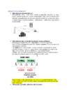
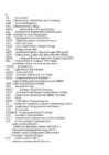

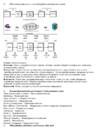

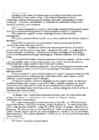


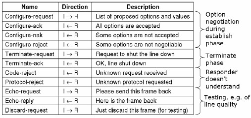
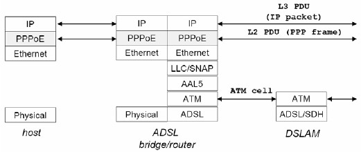
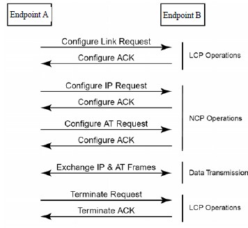
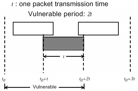
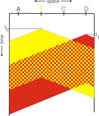
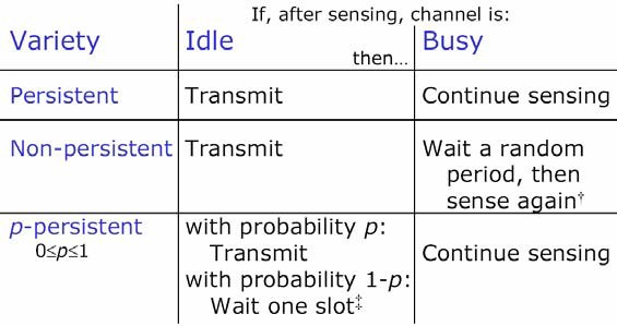
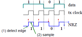
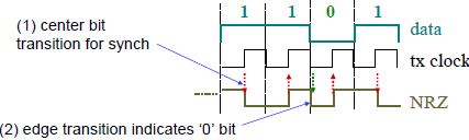
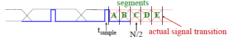
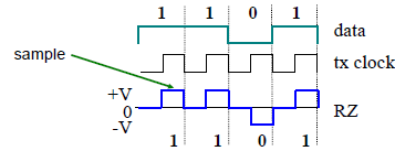
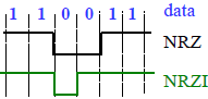
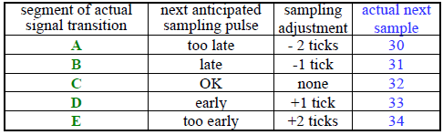
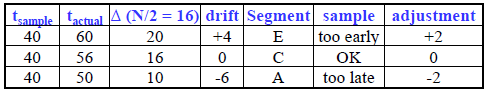
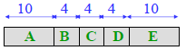
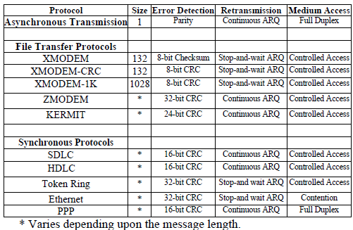
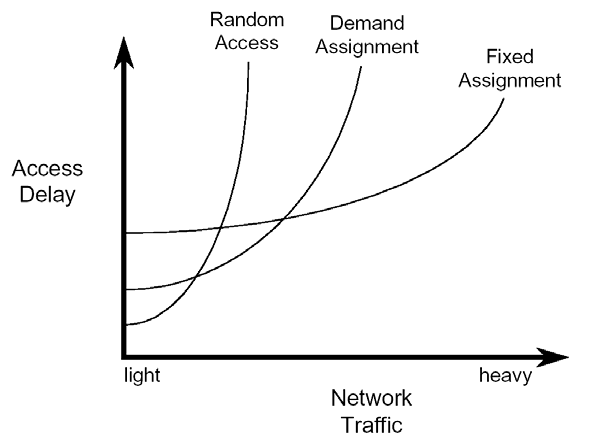
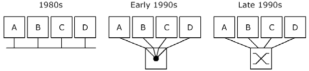


Kõik kommentaarid