Vajad kellegagi rääkida?
Küsi julgelt abi LasteAbi
Logi sisse

Värvitud Petri võrgud CPN eksami konspekt (0)

1 Hindamata
Punktid
  • System development
    • Modelling in early system development stage corrects design errors before construction .
    • Beneficial modelling reasons (– Insight: in the design and operation of a system –  Completeness: detection of missing parts for simulation and a better understanding of the system requirements –  Correctness: errors and flaws are usually detected, problematic scenarios can be reproduced, systematic error investigation)

  • Introduction CPN
    • CPN is a graphical language for concurrent system design and analysis and also general- purpose modelling environment and also applicable for industrial projects and high level programming.
    • Petri nets provide (– graphical notation– modelling concurrency, communication , synchronisation)
    • CPN application domains that are typical (– communication protocols, data networks , distributed algorithms )
    • Broader CPN applications for concurrent systems(– business processes and workflows, manufacturing systems, multi- agent systems)
    • CPN models are(–  executable and used to model and specify the behaviour of concurrent systems- events cause the system to change states –  simulations of the model to investigate different scenarios and explore the behaviour –  simulations is to debug and investigate the system design –  interactive for the simulation with single -step debugging–   Automatic simulations with breakpoint setting.
    • The concept of CPN modules(– based on a hierarchical structuring mechanism - allows a module to have sub-modules– allows module-composition into a new module – reuse of sub-modules in different model parts– allows modeller to work bottom -up & top-down)
    • Visualization in CPN modules is important for(– presentation of design ideas & analysis results – discussion with people unfamiliar to CPN– abstractly visualizing a CPN module execution for an application context )
    • Verification involves(– a mathematical formulation of a property– a computer- assisted proof that a model satisfies a property– verified properties must be those a system should possess– informal justification always accompanies formal verification)
    • Two types of simulation (– interactive simulation( user is in complete control ; user determines individual simulation steps; execution events are GUI visible )– automatic simulation (user specifies number of execution steps in the GUI; and/or user sets a number of stop criteria and breakpoints; simulator makes random choices without user interaction; only the resulting state is shown via the GUI; a simulation report contains results))

    3. A Single-example protocol / Net structure
    • The transport layer(– ensures reliable transmissions between hosts – the sender transfers data packagets to a receiver – unreliable communication network – use of sequence numbers , acknowledgements, retransmissions)
    • Next to places an inscription determines token colours( colset NO = int) - NO is the sequence number in the protocol - NOxDATA is the product of types NO and DATA - The colour sets are colset DATA = string and colset NOxDATA = product NO * DATA - DATA is the payload - NOxDATA is the data packets - The initial marking is in state PacketsToSend - ++and ‘ are operators used to construct a multiset - The infix operator ‘ specifies the number of appearances - Transition occurs, removes tokens from its input places - The transition adds tokens to its output places - Arc expressions determine which tokens are removed

    4.Concurrency and conflict
    • CPN allows to modelling concurrent systems

    In the marking M1, three different binding elements are enabled:
    • TP+ and TP−, are in conflict with each other (– both are enabled, only one can occur per token in A)
    • SP and TP+ can occur concurrently(– SP needs a token on the place PacketsToSend and a token on NextSend, while TP+ needs a token on place A– no competition or interference to get tokens)
    • SP and TP− are concurrently enabled(– they also use disjoint input tokens, occur concurrently)

    5.Guards
    • Besides input arcs, also transitions may carry guards. Guard is a boolean expression that must evaluate to true for binding. A guard puts an extra constraint on the enabling of bindings for a transition.

    6.Interactive simulaton
    • An execution of a CPN model is described by means of an occurrence sequence which specifies the intermediate markings reached and the steps that occur
    • A reachable marking is a marking that is reachable via an occurrence sequence starting from the initial marking
    • A non-deterministic CPN model– existence of a reachable marking with more than one enabled binding element. This means that  there exist different occurrence sequences containing different sequences of steps and  leading to different reachable markings. The individual steps themselves are deterministic.

    7. Functional programming
    • CPN ML extends Standard ML with constructs for defining color sets and declaring variables.
    • Standard ML also used for implement simulation, state- space analysis and performance analysis.
    • CPN ML is a functional programming language (– functions are treated in the same way as basic values – functions can be passed as arguments to functions– recursive functions are used to express iterative constructs)

    8.Color sets
    • CPN ML provides a predefined set of basic types that can be used as simple color sets and that can be used to define structured color sets
    • CPN protocol model description (– data packets were modeled as a product– tuples consisting of an integer and a string– a field representing the sequence number – another field representing the data content– duplication of packets becomes possible)


    b+ = ⟨ pack =Data({seq=1,data="COL"}), res= success
    b− = ⟨pack=Data({seq=1,data="COL"}), res= failure
    b++ = ⟨pack=Data({seq=1,data="COL"}), res=duplicate⟩
    b+, represents a successful transmission over the network. When it occurs the data packet (1,"COL") is removed from the input place A. A new token representing the same data packet is added to the output place B
    b−, represents an unsuccessful transmission. When this binding occurs the data packet (1,"COL") is removed from the input place A. No token is added to the output place B
    If the binding element b++ occurs, arc expression on the arc from TransmitPacket to B evaluates to 2‘Data({seq=1,data="COL"})
    9.Net structure and inscriptions
    10.Occurrence of steps
    11.Model parameterization
    • RECV.all is a predefined color set function (– takes a unit () as an argument– returns the list representation of a multiset– containing one appearance of each of the colors in RECV)
    • List.map is also a predefined function (– takes a function and a list as arguments – applies the function to each list element)
    • Fusion sets to glue places from different modules (– compound places across hierarchical structure)

    12.Unfolding hierarchical CPN
    • Three unfolding steps (– Replace each substitution transition (with the content of its associated submodule; related port and socket places are merged into a single place)– Collect the content of all resulting prime modules into a single mod – Merge the places in each fusion set into a single place)

    13.State Space
    • The state-space method supports CPN model verification(– compute all reachable states & state changes automatically– represent as directed graph – nodes represent states and arcs occurring events – answer verification questions about system behaviour – state spaces give counter examples with debugging info – user must not worry about deeper underlying mathematics – disadvantage of state-space explosion)

    14.Protocol for state space
    • The running example(– has an infinite number of reachable markings– the state space cannot be calculated– places A, B, C, D can contain an arbitrary number of tokens)
    • To obtain a finite number of reachable markings(– limit tokens to simultaneously reside in places A, B, C, D – add extra place of color set UNIT – the initial marking Limit is the multiset 3‘() )
    • Simulation can only be used to explore a finite number of executions of the system under consideration .
    • State-space construction continues until no unprocessed nodes remain .
    • Node processing one by one, in some abritrary order .
    • If the state space is finite, the construction will terminate when we have processed all reachable markings.
    • Create a state-space report (– answers initial behavioural properties–  early-design phase errors evident in state-space reports –  user can draw interactively selected parts to inspect individual states & events)

    15.SSC graph
    • The SCC graph is used by the CPN state space tool to check behavioral properties of a model.
    • The nodes in the SCC graph are subgraphs and are obtained by disjoint division of nodes in state space.
    • The label of an arc in an SCC graph is the label of the corresponding arc in the state space. Since an SCC graph groups nodes that are mutually reachable, it follows that an SCC graph is an acyclic graph.
    • Terminal SCC – SCC without outgoing arcs
    • Ttrivial SCC – single state space node and no state space arcs

    16.Behavioural properties
    • The reachability properties are concerned with determining whether a markingM’ is reachable from another markingM.
    • Boundedness spesify amount of tokens of a place may hold (- best upper integer bound ( maximum tokens in a place at any reachable marking)– best lower integer bound( minimal tokens in a place at any reachable marking ) - Best upper multiset bound( max tokens of given colors in a place at any reachable marking) - Best lower multiset bound( min tokens of given colors in a place at any reachable marking))
    • Home properties (– a further generalization of a home spaces– from any reachable marking it is always possible to reach a marking satisfying a home predicate)
    • Liveness properties tell us that there is a single dead markings
    • Fairness properties informs how often transitions occur in infinite occurrence sequences.

    17.Limitations of state spaces
    • Every time configuration changes (– state-space recalculation– new analysis )
    • Partial state-space analysis only(– when state-space too large– not useful for overal verification– still , systematic error-identification technique )

    18.State-Space-Reduction methods
    • State-space-reduction methods exploit certain characteristics of the system under analysis. Furthermore, the methods often limit the verification-question answers. Also use two or more reduction methods.
    • On-the-fly verification means that the verification question stated before state-space exploration.
    • Sweep-Line Method exploit a certain kind of progress exhibited by many systems and makes possible to store small fragment of state space in memory . This means that the peak memory usage is significantly reduced.
    • Symmetry Method represents symmetric markings and symmetric binding elements using equivalence classes. State spaces can be condensed by factoring out this symmetry, and the symmetry-condensed state space is typically orders of magnitude smaller than the full state space.
    • The equivalence method is a generalisation of the symmetry method, where the constraint that the equivalence relations are induced by symmetries is removed. Instead, arbitrary equivalence relations on the markings and binding elements can be used provided that they are consistent.

    19. Timed CPN
    • With a timed CPN performance measures can be calculated and also verifying if real -time system operations meet deadlines.
    • Times examples are non-hierarchical CPN model and in hierarchical CPN models can use timing constructs.
    • Main difference timed– second timestamp value for tokens– markings is now a timed multiset– CPN model has a global clock.
    • In hierarchical timed CPN model a single global clock shared among all of the modules.
    • Timestamps are non- negative integers which specifies when a token is ready to be used.
    • First timed model seletus(In the initial marking M0 only one binding element and has the required tokens on its input places; Marking M1 when SendPacket occurs at time 0 in M0; M2 when TransmitPacket occurs at time 9 in M1; M3 reached when ReceivePacket occurs at time 47 in M2; M5 reached when ReceiveAck occurs at time 97 in M4; M6 reached when SendPacket occurs at time 104 in M5)
    • Second Timed model seletus (M1 reached when SelectNext occurs at time 0 in M0; M2 reached when SendPacket occurs at time 0 in M1; M3 where an acknowledgement arrives at time 94; M4 reached when ReceiveAck occurs at time 94 in M3; M2 reached when StopTimer occurs at time 101 in M3; When a time delay inscription is used on a double -headed arc in a timed CPN model, it is a shorthand for an arc in both directions with the same arc expression, including the time delay inscription.

    20.State space of Timed model
    • Each state space node now represents a timed marking
    • Occurrence sequence in a timed CPN model corresponds to untimed CPN model. Timed state space is larger than untimed state space (nodes in timed state space are timed markings)- two timed markings can be different (timing information makes more markings distinguishable)
    • State space timed seletus- M1 reached when SendPacket occurs at time 0 in M0; M2 reached when TransmitPacket occurs at time 9 in M1)

    21.Simulation based
    • Performance analysis evaluate existing or planned system- compare alternative implementations and to find optimal system configurations. It also conducts a number of lengthy simulations of a CPN model.
    • Simulation output data exhibit random behaviour and appropriate statistical techniques must be used both to design and to interpret simulation experiments.

    22.Data collection occuring
    • Data collection monitor functions include a predicate function that determines when data should be collected and an observation function that determines what data is to be collected. Monitor also has a start function to collect data from the initial marking and also a stop function to collect data from the marking reached at the end of a simulation. A monitor has an associated set of places and/or transition.
    • Collect data from markings reached during a simulation. Firstly, investigate data-packets amount in sender queue .
    • Data collection monitors make repeated measurements/observations of quantities and calculates for data value (the regular average -the time average)
    • Simulation replications in CPN Tools calculate performance measure estimates.

  • Vasakule Paremale
    Värvitud Petri võrgud CPN eksami konspekt #1 Värvitud Petri võrgud CPN eksami konspekt #2 Värvitud Petri võrgud CPN eksami konspekt #3 Värvitud Petri võrgud CPN eksami konspekt #4 Värvitud Petri võrgud CPN eksami konspekt #5 Värvitud Petri võrgud CPN eksami konspekt #6
    Punktid 10 punkti Autor soovib selle materjali allalaadimise eest saada 10 punkti.
    Leheküljed ~ 6 lehte Lehekülgede arv dokumendis
    Aeg2017-06-16 Kuupäev, millal dokument üles laeti
    Allalaadimisi 2 laadimist Kokku alla laetud
    Kommentaarid 0 arvamust Teiste kasutajate poolt lisatud kommentaarid
    Autor lotatimmu Õppematerjali autor
    Coloured Petri Nets CPN eksami konspekt

    Sarnased õppematerjalid

    IT arhitektuur
    44
    doc

    IT arhitektuur

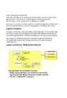
    1.The Conceptual Architecture identifies the high-level components of the system, and the relationships among them. Its purpose is to direct attention at an appropriate decomposition other system without delving into details. Moreover, it provides a useful vehicle for communicating the architecture to non-technical audiences, such as management, marketing, and users. Logical Architecture In Logical Architecture, the externally visible properties of the components are made precise and unambiguous through well-defined interfaces and component specifications, and key architectural mechanisms are detailed. The Logical Architecture provides a detailed "blueprint" from which component developers and component users can work in relative independence. Logical Architecture. Model System Behavior Execution Architecture An Execution Architecture is created for distributed or concurrent systems. The process view shows the mapping of components onto the processes of the physical system, with atte

    It arhitektuur
    Thesis Kivimaa August 2022
    140
    pdf

    Thesis Kivimaa August 2022

    Thesis “How is it possible to calculate IT security effectiveness?” Kristjan Kivimaa August 2022 1 Abstract In IT Security world, there is lack of available, reliable systems for measuring security levels/posture. They lack the range of quantitative measurements and easy and fast deployment, and potentially affects companies of all sizes. Readily available security standards provide qualitative security levels, but not quantitative results – that would be easily comparable. This deficiency makes it hard for companies to evaluate their security posture accurately. Absence of security metrics makes it complicated for customers to select the appropriate measures for particular security level needed. The research question for this research project is – “How is it possible to calculate IT security effectiveness?”. The aim of this research is to use this reference m

    Infotehnoloogia
    Tööstuslik andmeside kontrolltöö 2 abimaterjal - vastused
    3
    doc

    Tööstuslik andmeside kontrolltöö 2 abimaterjal - vastused

    oData transparency: In bit and byte oriented protocols, there is a problem if a control character (for ETX (End of Text) ·Same as ETB, only no more blocks will follow. ITB (End of > Differences with HDLC ­ length of protocol field (1B or 2B) byte-oriented protocols) or the start-of-frame flag (for bit-oriented protocols) appears in the actual data. Intermediate Transmission Block) ·Same as ETB, except that the receiving statio Differs from HDLC because of multiaccess MAC that provides · Maximum payload length (default: 1500) This was not likely to happen in ASCII text, but is very likely with binary data. This is known as a data will not acknowledge after the error checking. EOT (End of Transmission) framing/error detection: · Type of CRC (2B or 4B) transparency problem an can be rectified with byte stuffing (for byte-orien

    Tööstuslik andmeside
    Tarkvara kokkuvõte inglise keeles
    36
    doc

    Tarkvara kokkuvõte inglise keeles

    (UML1.1) ,industrialization. =>1.3.01.4.1.5 2.0 AN Architectural representation: logical ,implementation, process, deployment views Use Case Diagramm shows all the ways of using the system; classifiers can now own use cases. Associated Diagrams: activity d.-can be used to model interaction between scenarios. Activity Diagram: Focus on flow of activities involved in a process. Significant changes from UML1.X-now address real time flow,incorporated Petri Net concepts -decompose activity into multiple actions -activity parameters and pins Useful because they focus on workflow-don’t have to reference a prticular object so ideal to map complex alternarive flows in a use case. Visual map of a set of activities and possible transitions between them –activities by one or more operations. Activity Modeling •The sequence and conditions for coordinating other behaviors

    Tehnoloogia
    CPM1A Programmable Controllers Operation Manual 1784470
    402
    pdf

    CPM1A Programmable Controllers Operation Manual 1784470

    Cat. No. W317-E1-11 SYSMAC CPM1A Programmable Controllers OPERATION MANUAL CPM1A Programmable Controllers Operation Manual Revised October 2007 iv Notice: OMRON products are manufactured for use according to proper procedures by a qualified operator and only for the purposes described in this manual. The following conventions are used to indicate and classify precautions in this manual. Always heed the information provided with them. Failure to heed precautions can result in injury to people or dam- age to property. ! DANGER Indicates an imminently hazardous situation which, if not avoided, will result in death or serious injury. Additionally, there may be severe property damage. ! WARNING Indicates a potentially hazardous situation which, if not avoided, could result in death or serious inju

    Automatiseerimistehnika
    Kuidas muudab mudelprojekteerimine teraskonstruktsioonide valmistamist ja ehitamist
    228
    pdf

    Kuidas muudab mudelprojekteerimine teraskonstruktsioonide valmistamist ja ehitamist

    EHITUSTEADUSKOND Ehitustootluse instituut KUIDAS MUUDAB MUDELPROJEKTEERIMINE TERASKONSTRUKTSIOONIDE PROJEKTEERIMIST, VALMISTAMIST JA EHITAMIST? HOW ARE 3D AND BIM CHANGING THE DESIGN, FABRICATION AND CONSTRUCTION OF COMPLEX STEEL STRUCTURES? EPJ 60 LT Üliõpilane: Tanel Friedenthal Juhendaja: Prof. Roode Liias Kaasjuhendaja: Prof. Carrie S. Dossick Tallinn, 2010.a. Olen koostanud lõputöö iseseisvalt. Kõik töö koostamisel kasutatud teiste autorite tööd, olulised seisukohad, kirjandusallikatest ja mujalt pärinevad andmed on viidatud. …………………………………………….. (töö autori allkiri ja kuupäev) Üliõpilase kood: 041399 Töö vastab magistritööle esitatud nõuetele …………………………………………?

    Ehituskonstruktsioonid
    Games Programming with Java and Java 3D
    23
    pdf

    Games Programming with Java and Java 3D

    Games Programming with Java and Java 3D Andrew Davison Dept. of Computer Engineering Prince of Songkla University HatYai, Songkhla 90112 E-mail: [email protected] Draft: 14th January 2003, #2 Abstract This article looks at the advantages and disadvantages of using Java and Java 3D for games programming. It assumes the reader is familiar with Java, but presents short overviews of gaming, the low-level APIs OpenGL and DirectX, and Java 3D. No programming examples are included here, although links to online code are supplied. 1. Background to Gaming Giving a definition for `computer game' is problematic, due to the wide range of game types. For example, the ArcadePod site (http://www.arcadePod.com) divides its hundreds of Java games into more than ten categories: 3D games, multiplayer, action

    Java programmeerimine
    Book Analog Interfacing to Embedded Microprocessors
    568
    pdf

    Book Analog Interfacing to Embedded Microprocessors

    Analog Interfacing to Embedded Microprocessors Real World Design Analog Interfacing to Embedded Microprocessors Real World Design Stuart Ball Boston Oxford Auckland Johannesburg Melbourne New Delhi Newnes is an imprint of Butterworth–Heinemann. Copyright © 2001 by Butterworth–Heinemann A member of the Reed Elsevier group All rights reserved. No part of this publication may be reproduced, stored in a retrieval system, or transmitted in any form or by any means, electronic, mechanical, photocopying, recording, or otherwise, without the prior written permission of the publisher. Recognizing the importance of preserving what has been written, Butterworth–Heinemann prints its books on acid-free paper whenever possible. Library of Congress Cataloging-in-Publication Data Ball, Stuart R., 1956– Analog interfacing to embedded microprocessors : real world design / Stuart Ball. p. cm. ISBN 0-7506-7339-7 (pbk. : alk. paper) 1. Embedded computer

    Mehhatroonika


    Meedia

    Kommentaarid (0)

    Kommentaarid sellele materjalile puuduvad. Ole esimene ja kommenteeri


    Sellel veebilehel kasutatakse küpsiseid. Kasutamist jätkates nõustute küpsiste ja veebilehe üldtingimustega Nõustun