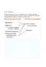
identifies the high-level
components of the system, and the relationships
among them . Its
purpose is to
direct attention at an appropriate decomposition
other system
without delving into
details .
Moreover, it provides a useful
vehicle for communicating the architecture to non-technical
audiences,
such as
management ,
marketing , and
users .
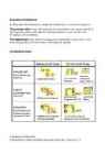
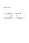
Logical ArchitectureIn Logical Architecture, the
externally
visible properties of the components are made precise and
unambiguous
through well-defined interfaces and
component specifications, and key architectural mechanisms are detailed.
The Logical Architecture
provides a detailed “blueprint” from which component developers
and component users can
work in relative independence.
Logical Architecture. Model System Behavior Execution ArchitectureAn Execution Architecture is
created for distributed or concurrent systems.
The process view shows the
mapping of components onto the
processes of the
physical system, with attention being focused on such concerns as throughput
and scalability.
The deployment
view shows the mapping of (physical) components in the
executing system onto the nodes of the physical system.
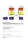
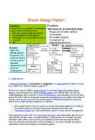
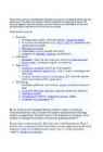
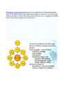
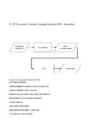
Architecture views 2. Business Architecture
A formalized model of what the
business looks like, in
terms of IT.
Information ArchitectureLogical
description of the
translated Business Architecture in IT terms.
The IA is on high level in
terms of functionality and data management.
Technical ArchitectureTechnical Architecture refers
to the
–technical infrastructure,
–operations and processes,
Required to create and
support the Information Architecture.
Applications ArchitectureThe Applications Architecture
refers to how useful applications are
–structured,
–procured and
–life –
cycle managed .
Applications Architecture User Systems ArchitectureCovers all architecture
aspects of Information, Technical and Applications Architecture.
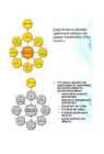
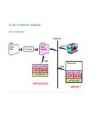
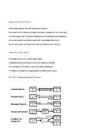
3 Model–view–controller(MVC) is an architectural
pattern
used in software
engineering .
Successful use of the pattern isolates business
logic
from user
interface considerations, resulting in an
application where it is
easier to
modify either the
visual appearance of the application or the
underlying business
rules without affecting the other. In MVC, the
model
represents the information (the data) of the application; the
view
corresponds to
elements of the user interface such as text, checkbox
items , and so
forth ; and the
controller
manages the
communication of data and the business rules used to
manipulate the data to and from the model.
4. design pattern
MVC
encompasses more of the architecture of an application
than is
typical for a design
pattern.[
citation needed]
When
considered as a design pattern, MVC is semantically
similar to
the Observer
pattern.
Model
Is
the
domain -
specific representation of the information on which the application operates.
Domain logic adds
meaning to raw data (for example, calculating
whether
today is the user's birthday, or the totals, taxes, and
shipping charges for
shopping cart items).
Many
applications use a
persistent storage mechanism (such as a database)
to store data. MVC does not specifically mention the data
access layer because it is
understood to be underneath or encapsulated by
the model.
View
Renders
the model into a form suitable for interaction,
typically a user
interface
element. Multiple views can
exist for a
single model for
different purposes.
Controller
Processes
and responds to events (typically user
actions ) and may indirectly
invoke
changes on the model.
In
computer
programming, the
proxy pattern is a software
design pattern.
A
proxy, in its most general form, is a
class functioning as an
interface to
something else . The proxy
could interface to
anything : a
network connection , a large
object in
memory , a file, or some other
resource that is
expensive or impossible to duplicate.
A
well-
known example of the proxy pattern is a
reference counting pointer
object.
In
situations where multiple copies of a
complex object must exist the
proxy pattern can be adapted to incorporate the flyweight
pattern in
order to reduce the application's memory
footprint. Typically one
instance of the complex object is created,
and multiple proxy objects are created, all of which
contain a
reference to the single
original complex object. Any operations
performed on the proxies are forwarded to the original object.
Once all instances of the proxy are out of
scope , the complex object's
memory may be de allocated.
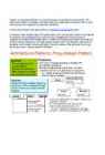
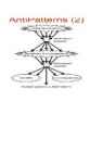
6. Antipatterns
In
software
engineering,
an
anti-pattern
(or
antipattern)
is a design
pattern
that
appears obvious but is ineffective or far from optimal in
practice .[1][2]
The
term was coined in 1995 by
Andrew Koenig,[3]
inspired by
Gang of
Four 's
book
Design Patterns ,
which developed the
concept of design
patterns
in the software
field . The term was widely popularized three
years later by the book
AntiPatterns,
which
extended the use of the term beyond the field of software
design and into general
social interaction.
According to the
authors of the
latter ,
there must be at
least two
key elements
present to formally distinguish an actual anti-pattern
from a
simple bad
habit ,
bad practice, or bad
idea :
Often
pejoratively
named with clever oxymoronic
neologisms,
many anti-pattern
ideas amount to
little more than mistakes, rants,
unsolvable problems, or bad
practices to be avoided if possible.
Sometimes called
pitfalls
or
dark patterns,
this informal use of the term has
come to refer to
classes of
commonly reinvented bad
solutions to problems. Thus, many
candidate anti-patterns under debate would not be formally considered
anti-patterns.
By
formally describing repeated mistakes, one can recognize the forces
that
lead to their repetition and learn how
others have refactored
themselves out of
these broken patterns.
is
a framework
for enterprise
architecture,
which provides a
formal and
highly structured way of viewing
and defining an enterprise.
The
Framework in practice is used for organizing enterprise architectural
"artifacts" in a way that
takes into
account both :
- who the artifact targets for example, business owner and builder , and
- what particular issue for example, data and functionality is being addressed.
These
artifacts may
include design
documents , specifications, and
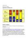
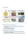
models.[3]Scope
(Ballpark) View. This view describes the business purposeand
strategy , which defines the
playing field (ballpark) for
theotherviews. It serves as the
context within which the other views
will bederived and managed.
Owner's
View (Enterprise Model). This
is a description of the
organization
within which the information system must
function .
Analyzing
this view reveals which parts of the enterprise can be
automated.
Designer's
View (System Model).
This view outlines how the
system
will satisfy the organization's information
needs . The
representation
is free from solution-specific aspects or productionspecific
constraints .
Builder's
View ( Technology Model).
This is a representation of
how
the system will be implemented. It
makes specific solutions
and
technologies apparent and addresses
production constraints.
Out-of-Context
View (Detailed Models).
These representations
illustrate
the implementation-specific details of certain system
elements:
parts that need
further clarification
before production can
begin .
This view is less architecturally significant than the others
because
it is more concerned with a
part of the system than with
the
whole .
Operational
View (Functioning System).
This is a view of the
functioning
system in its operational environment.
8. Open Group Architecture Framework
(TOGAF)
The
Open Group Architecture Framework
(TOGAF) is a framework
for enterprise
architecture
which provides a comprehensive
approach to the design,
planning ,
implementation, and governance of an enterprise information
architecture.
The
architecture is typically modelled at four levels or domains;
Business, Application, Data, Technology. A set of foundation
architectures are
provided to enable the architecture
team to
envision the
current and future state of the architecture.
TOGAF
is that it isn't actually an architecture, but
rather a framework
fordesigning and describing an architecture.
•An
architectural framework is a
classification system forarchitectural
descriptions.
–In
other
words , instead of helping you
describe a particular
Service -Oriented Architecture (SOA) system, TOGAF can help you decide
whether SOA is right
for the project at all.TOGAF
is very much a top-down methodology.
•As
with all top-downmethods, it starts with the big
picture and breaks
it down into progressively smaller pieces.
•But
TOGAF isintended to be a generic
method , one that works with any
architecture.
–What
happens when you are using a morebottom-up style, such as SOA, which
starts with specific
functions and builds them into a larger system?
Many
enterprise architecture frameworks break down the practice of
developing artifacts into four practice
areas . This allows the
enterprise to be described from four
important viewpoints. By
taking this approach, enterprise
architects can assure their business
stakeholders that they have provided sufficient information for
effective decision
making .
These
practice areas are
Business:
Strategy maps, goals, corporate policies, Operating Model
Functional decompositions (e.g. IDEF0, SADT), capabilities and organizational models
Business processes
Organization cycles, periods and timing
Suppliers of hardware, software, and services
Information:
Metadata - data that describes your enterprise data elements
Data models: conceptual, logical, and physical
Applications:
Application software inventories and diagrams
Interfaces between applications - that is: events, messages and data flows
Intranet , Extranet, Internet , eCommerce, EDI links with parties within and outside of the organization
Technology:
Hardware, platforms, and hosting : servers, and where they are kept
Local and wide area networks , Internet connectivity diagrams
Operating System
Infrastructure software: Application servers, DBMS
Programming Languages , etc..
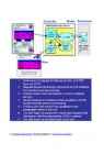
10.
The Architecture Development Method (ADM) is applied to develop an enterprise architecture which
will meet the business and information technology needs of an
organization. It may be tailored to the organization's needs and is
then employed to manage the execution of architecture planning activities .[5]
The
process is iterative and cyclic. Each step checks with Requirements .
Phase C involves some combination of both Data Architecture and
Applications Architecture. Additional clarity can be added between
steps B. and C. in order to provide a complete information
architecture.
Performance engineering working practices are applied to the Requirements phase, and to the
Business Architecture, Information System Architecture, and
Technology architecture phases. Within Information System
Architecture, it is applied to both the Data Architecture and
Application Architecture.
9. TOGAF 9 COMP
TOGAF
9 includes many new features including
- Increased rigor including a formal Meta Model that links the artifacts of TOGAF together
- Elimination of unnecessary differences
- Many more examples and templates.
Additional guidelines and techniques include
- A formal business-driven approach to architecture scoping and segmetation
- Business capability- based planning
- Guidance on how to use TOGAF to develop Security Architectures and SOAs
11.SW Component
A
software component is a unit of composition with contractually
specified interfaces and context dependencies only. A software
component can be deployed independentlyand is subject to composition
by third parties
12. Distributed Component
13. Java Architecture, JavaBeans
Java Architecture
JavaBeans
JavaBeans are reusable
software
components for Java
that can be manipulated visually in a builder tool . Practically, they
are classes written in the Java
programming language conforming to a
particular convention. They are used to encapsulate many objects into
a single object (the bean ), so that they can be passed around as a
single bean object instead of as multiple individual objects. A
JavaBean is a Java Object that is serializable,
has a no-argument constructor,
and allows access to properties using getter
and setter methods.
• Beans export functionality through PropertiesandMethods:
–Methodssuch as contains()can be accessed fromany other
entity.
•They define the behavior of a bean.
–Propertiessuch as backgroundColordefine theappearance of a
bean.
•They are getor setfrom otherentities for
customization and programmatic use.
•Beans are customized by modifying theirproperties. A user can
customize a beanby:
–programmaticallychanging properties or
–editing properties within a builder tool using
PropertySheets & Editorsor
–automatically being guided through customization bycustomizers,
i.e. graphical user interfaces sometimesalso denoted as wizards.
•What about the packaging of beans ?
–Beans are delivered using compressed archive files (JARfiles).
–JAR files contain the class files of beans as well asresource
files such as images, sounds, videos.
•Inaddition, a manifestfile describes the contents of thearchive.
Problems:
•Security: Since beans run in the same address spaceas their
container, the same security restrictionsapply. Never assume a
specific trust level for yourbean.
• Multi -threading:Always suppose , your bean isrunning in a
multi-threaded environment when youdesign its properties, methods and
event-handling.
•Constructors:Must provide a default constructor.
14. COM Architecture
COM Principles
•Rigorous Encapsulation
– Black box --no leakage of implementation details
–All object manipulation through strict interfaces
•Polymorphism
–via multiple interfacesper class
–“Discoverable”: QueryInterface
What is ActiveX?
•A marketing name for a set of technologies and services, all based
on COM (the model, the “ORB”, and the services)
Active Components
•ActiveX Controls
–Are COM components with “design-time”UI
–Can be written in C++, VB, Delphi, ...
–Self-registering
–Optimized for download and execute
•Work on both Active Client or Server
–Can talk indirectly over HTTP or directly over COM
COM (Common Object Model)
•liidesed(= lepingud )
•kapseldus(meetodid, omadused, sündmused)
–QueryInterface–multiversionaalsus
•Binaarstandard(C++, VB, ...)
•DCOM (distributed) –asukohaläbipaistvus
15
.NET-processes, Common Language Runtime, MSIL, Assemblies
Common Language Runtime(CLR)
•.NET-käituskeskkond
–haldab programmikäituse(execution management)
–tagab teenused(provides services)
•Hallatud kood(managed code), tagab keeltevahelise:
–integratsiooni( cross language integration)
–versioonihalduse
–automaatse mäluhalduse
–isekirjelduvad objektid(IDL-i pole vaja)
–”Compileonce, runverywhere”
CLR (2) -metaandmed
•Kompilaatorid loovad koos koodiga ka metaandmed , mis:
– kirjeldavad komponente, objekte ja
käitustingimusi(klassideasukohtja laadimine, koodigenereerimine,
käituskontekst, ...)
–tagavad automaatse objektide eluea (garbagecollection)
•CLRitoetavad: Visual Basic , C#, Visual C++,
Perl (¬MS), COBOL (¬MS)
Common Language Specification(CLS)
CLR (3) -käitusehaldus
•MSIL ( Microsoft Intermediate language)
•JIT (Just In Time) kompileerimine
•Käitus(Execution)
•Assemblies
•Rakendusdoomenid(ApplicationDomains)
•Käitusajahostid(RuntimeHosts)
CLR (4) -JIT
•Osa programmi ei täideta konkreetses käituses MSIL-kood
konverteeritakse masinakoodiks ja laaditakse mällu vaid siis, kui
vaja
•Laadur loob igale meetodile vahendaja (stub)
•Järgnevad pöördumised suunatakse juba loodud masinakoodi poole
•Konverteerimisel verifitseeritakse koodi metaandmeid
kasutatades–safecode
CLR (4) -Assemblies
• Assembly –käitusühik.
–annab CLR-leinfo tüüpide implementeerimiseks
–assembly on failide hulk, assembly omab faile
•Staatilised assembly-d sisaldavad NET- karkassi ressurse(nt JPEG -failid)
•Dünaamilised assembly-d luuakse skriptide täitmise tulemusel,
neid ei salvestata kettale
•Assembly on ”loogiline.dll”(realiseerimisühik,
versioonihaldus, turvaõigused, ...)
•Assembly Manifest sisaldab kõik vajalikud Assembly metaandmed
16. Remote Procedure Call
•The remote procedure call (RPC) provides programmers a familiar
programming model by extendingthe local procedure call to a
distributed environment.
•RPC maintains the useful aspects of the localprogramming model while handling purely distributed issues such as
–server selection (binding), and
–communication or server failures.
•RPC alsoprovides a convenient and consistent mechanism for
specifying the interactions between componentsof a distributed
system.
•In addition to basic RPC features, such as supporting a variety of
data types and transportindependence, the remote procedure call needs
to support extended features such as
–context handles, allowing a server to reclaim resources when
either the communications or clientfails
–multiple language bindings, allowing applications to be
implemented in different programminglanguages
–orderly quit, allowing the application to cancel outstanding
requests
–national language support, allowing data types from
multibytecharacter sets to be supported
17. What is a Distributed System?
•Distributed system- requires autonomous computers to be
interconnected through a network.
•Each computer has to be equipped with distributed operating system
software, which enables the computers to coordinate activities and to share resources in a controlled way.
•We also requiretransparencyof distribution for the computer users.
–They shall not have to be aware of the fact that the system is
distributed.
Distributed System Characteristics
•Multiple autonomous components
•Components are not shared by all users
•Resources may not be accessible
•Software runs in concurrent processes on different processors
•Multiple Points of control
•Multiple Points of failure
•Certain requirements are common to many distributed systems
–Resource Sharing
–Openness
– Concurrency
–Scalability
– Fault Tolerance
– Transparency
18. Transparency in Distributed
Systems
•Distributed systems should be perceived by users and application
programmers as a wholerather than as a collection of cooperating
components.
•Transparency has different dimensions.
–These represent various properties that distributed systems should
have.
Access Transparency
•Enables local and remote information objects to be accessed using
identical operations.
•Example:SQL Queries
Location Transparency
•Enables information objects to be accessed without knowledge of
their location .
•Example:Pages in the Web
•Example:Tables in distributed databases
Concurrency Transparency
•Enables several processes to operate concurrently using shared
information objects without interference between them.
•Example: Automatic teller machine network
•Example:Database management system
Replication Transparency
•Enables multiple instances of information objects to be used to increase reliability and performance without knowledge of the
replicas by users or application programs
•Example:Distributed DBMS
Failure Transparency
•Enables the concealment of faults
•Allows users and applications to complete their tasks despite the
failure of other components.
•Example:Database Management System
Migration Transparency
•Allows the movement of information objects within a system without
affecting the operations of users or application programs
•Example:Web Pages
Performance Transparency
•Allows the system to be reconfigured to improve performance as
loads vary .
•Example:Load balancing.
Scaling Transparency
•Allows the system and applications to expand in scale without change to the system structure or the application algorithms.
•Example:World-Wide-Web
•Example:Distributed Database
A transaction is a sequence operation that is either performed completely or not at all. If it is completed, the effect of a
transaction is persistent and cannot be affected by failures.
Atomicity
•Transactions are sequences of operations that are clustered
together.
•Transactions, this cluster are either performed completely or
no modification is done .
•Start of a transaction is a continuation point to which it can
roll backif a single of its operations fails.
•If the transaction is completed successfully, the end of the
transaction (which is usually the start of the next transaction) marks the next continuation point.
Consistency
•The consistency property of a transaction requires that the
sequence of operations leaves the set of shared resources in a
consistent stateat the end of the transaction.
•Inconsistent states occur during transactions:
– hidden for concurrent transactions
•Within the transaction, after the debit has been completed but
before the credit has been executed, the set of account objects are
in an inconsistent state as the money is on neither accounts
–to be resolved before end of transaction.
•Application defines consistency and is responsible for ensuring it
is maintained.
•If the transaction has reached a certain state of inconsistency
that cannot be resolved, it can abort itself and recover to the
consistent state when it started .
Isolation
•Each transaction accesses resources as if there were no other
concurrent transactions.
•Modifications of the transaction are not visible to other
transactions before it finishes .
–In that way other transactions or unprotected activities can never
see an inconsistent state that may arise within a transaction
•Modifications of other transactions are not visible during the
transaction at all.
•Implemented through:
–two-phase locking
Durability
•The durability property requires the effect of a transaction to
be persistentso that it cannot be affected by failures.
•A completed transaction is always persistent (though values may be
changed by later transactions).
•Modified resources must be held on persistent storage before
transaction can complete.
•May not just be disk but can include battery-backed RAM or Flash RAM.
Transaction Commands
•Begin:
–Start a new transaction.
•Commit:
–End a transaction.
–Store changes made during transaction.
–Make changes accessible to other transactions.
•Abort(sometimes also referred to as rollback or undo ):
–End a transaction.
–Undo all changes made during the transaction.
20. Flat and Nested Transactions
FLAT
•In a flat transaction a transactional client issues begin
transaction, commit transaction or abort transaction commands .
•The transaction is successfully completed if it reaches the commit
statement.
•The transaction is not completed if it is either explicitly
aborted by the transactional client (if it encounters an
inconsistency that cannot be reconciled) or it is implicitly aborted
if a system failure occurs and it does not reach the commit.
•In a flat transaction it is not possible to start a transaction
within a transaction. For a transaction to be started there must not
be an ongoing transaction.
Nested
•The objective of having subtransactions is to be able to
set save points within a transaction in order to revert to these save
points.
–If an unreconcileable inconsistency is reached, it then becomes
possible to undo only a part rather than the whole transaction by
aborting only the subtransaction that caused the inconsistency.
–The parent transaction then continous at the point where the
aborted subtransactionwas started.
•To start a subtransaction, transactional clients invoke a begin
transaction operation from the transaction coordinator during the course of a parent transaction.
•With nested transactions it is, therefore , permitted to have a
begin transaction operation without having completed the previous transaction and such a begin will launch a subtransaction.
•Subtransactionscan have subtransactionsof their own, leading to an
arbitrary deep nesting hierarchy.
•If a parent transaction is aborted, however , the effect of all its
completed subtransactionsis undone.
•Consequently, if the root transaction is aborted all commited
subtransactionsare undone.
21. Two Phase Locking (2PL),
Deadlocks
2PL
•The most popular concurrency control technique. Used in:
–RDBMSs(Oracle, Ingres , Sybase, DB/2, etc.)
–ODBMSs (O2, ObjectStore, Versant, etc.)
–Transaction Monitors ( CICS , etc)
•Concurrent processes acquire locks on shared resources from lock manager .
•The principal component that implements 2PL is a lock manager from
which concurrent processes or threads acquire locks on every shared
resource they access.
•Lock manager grants lock if request does not conflict with already granted locks.
•Two phase locking guarantees serialisability.
Deadlock
•2PL may lead to processes waiting for each other to release locks.
•These situations are called deadlocks.
•Deadlocks have to be detected by the lock manager.
• Deadlock detection uses wait -for graph
•Deadlock ⇔wait-for graph
contains cycle
•Complexity of Detection: O(N) with N number of concurrent
transactions
•Deadlocks have to be resolved by aborting one or several of the
processes involved.
•This requires to undo all the actions that these processes have
done.
• Strategies :
–Abort Transactions that consumed least processor time
–Abort Transactions with most dependencies
22. The Two-Phase Commit Protocol
Roles of Components
•Distributed system components involved in transactions can take role of:
•Transactional Client
•Transactional Server
•Coordinator
Coordinator
•Coordinator plays key role in managing transaction.
•Coordinator is the component that handles begin / commit / abort
transaction calls.
•Coordinator allocates system-wide unique transaction identifier.
•Different transactions may have different coordinators.
Transactional Client
•Only sees transactions through the transaction coordinator.
•Invokes services from the coordinator to begin, commit and abort
transactions.
•Implementation of transactions are transparent for the client.
•Cannot tell difference between server and transactional server.
Two-Phase Commit
•Multiple autonomous distributed servers:
–For a commit, all transactional servers have to be able to commit.
–If a single transactional server cannot commit its changes every
server has to abort.
•Single phase protocol is insufficient.
•Two phases are needed:
–Phase one: Voting
–Phase two: Completion
Phase One
•Called the voting phase.
•Coordinator asks all servers if they are able (and willing) to
commit.
•Servers reply:
–Yes: it will commit if asked , but does not yet know if it is
actually going to commit.
–No: it immediately aborts its operations.
• Hence , servers can unilaterally abort but not unilaterally commit
a transaction.
Phase Two
•Called the completion phase.
•Co-ordinator collates all votes, including its own, and decides to
–commit if everyone voted ‘Yes’.
–abort if anyone voted ‘No’.
•All voters that voted ‘Yes’are sent
–‘DoCommit’if transaction is to be committed.
–Otherwise ‘Abort'.
•Servers acknowledge DoCommit once they have committed.
Recovery in Two-Phase Commit
•Failures prior to start of 2PC results in abort.
•Coordinator failure prior to transmitting commit messages results
in abort.
•After this point, co-ordinator will retransmit all Commit messages
on restart.
•If server fails prior to voting, it aborts.
•If it fails after voting, it sends GetDecision.
•If it fails after committing it (re)sends HaveCommittedmessage.
23. Major Data Warehousing
Activities
•Data extraction-obtaining data from operational and other data sources .
•Data transformation-since the data is extracted from a variety of
different systems and formats, it must be cleansed and standardized
into a common format.
•Data access and presentation-provides a variety of ways for users
to view the data .
24. Data Warehousing Components
•Data Migration Tools
–source data access, data transformation
•Metadata repositories
–source data description, transformation definitions ,data currency
• Warehouse Database
–integrated, subject-oriented, multidimensional
•Data Warehouse management
–data administration, –changes/modifications, etc., process
administration
•Data Access and Delivery
–reporting, analysis , data mining and discovery , data marts
25. Data Mart Development
•A data mart is similar to a data warehouse
• Designed for a specific department
•A data mart focuses on a single functional area
• Built from a subset of tables in the transaction database or
warehouse
•Two basic types of data marts: dependent and independent
Independent Data Marts
• Gets it data directly from the transaction systems
•Does not have the features of data integration, consistency, and
cleansing
•Cannot support the information requirements of enterprise-wide decisions
•Many data warehouse efforts begin with independent data marts
•Some data marts have both dependent and independent features
Dependent Data Marts
•Dependent data mart is warehouse-based
•‘Depends’on the data warehouse as the source for its data
•May actually be a subset or view of the data warehouse
•Provides summaries and aggregations of selected DW tables
26. Five Communication Patterns
27. The Concept of Message Oriented
Middleware
•High throughput and scalability to many thousands of senders and
receivers
•“ Quality of service”options, including guaranteed,“exactly
once”delivery
• Dynamic reconfiguration, such as the capability to add, delete or
move senders or receivers
•Queuing(store-and- forward )
•Publish-and-subscribe(subject-or content-based addressing
mechanisms)
28. Tightly Coupled RPC-based and
Hub-and- spoke Architecture
Tightly Coupled RPC
RPC attempts to mimic the behavior of a system that runs in one process.
When a remote procedure is invoked, the caller is blocked until the
procedure completes and returns control to the caller. This
synchronized model allows the developer to view the system as if it
runs in one process. Work is performed sequentially, ensuring that
tasks are completed in a predefined order. The synchronized nature of
RPC tightly couples the client (the software making the call) to the
server (the software servicing the call). The client cannot
proceed—it is blocked—until the server responds.
The
tightly coupled nature of RPC creates highly interdependent systems
where a failure on one system has an immediate and debilitating
impact on other systems. In J2EE, for example, the EJB server must be
functioning properly if the servlets that use enterprise beans are expected to function.
HUB and Spoke
In this architecture, applications are not connected directly with
each other. Instead, each application is connected to a hub that
provides connectivity between all the applications. A change or
upgrade to any one application changes only its relationship with the
hub and does not affect all the other applications with which it must
be integrated.
29. Fault Tolerant Computing
Fault Tolerant Requirements
1. Full -stateRecovery:
–In the event of a system failure, the secondary broker must be
able to assume the role of it sfailed primary partner. The secondary
broker must gracefully recover the full message stateprior to the
failure.
2.Hot-failover:
–In the event of a system failure, the secondary broker must
transition to an active state withminimum failover latency . Minimum
latency ensures that client application buffers will notoverflow or
applications fail.
3.ClientFailureTransparency:
–In the event of a system failure, enterprise applications must
transparently fails over to the secondary messaging broker. The
enterprise application connection to the message system stays warm
until the transition to the secondary broker is complete.
Traditional Fault Tolerant Solution
•In the event of a primary server failure, the third-party system
will initiate a fail-over process to the secondary server.
–The secondary server begins reading message state information from
the shared database and initializing internal logs and files.
–This failover process may take several minutes or longer.
–The fault tolerance system also notifies enterprise applications
of the failure and provides re-connection information.
–The client applications connect to the secondary server and
complete the recovery process.
•Despite this complex process, the failover and re-initialization
process still does not provide exactly once message reliability.
•Enterprise client applications may still encounter
trapped,duplicated, out-of-order and broken transactional messages.
•All four messaging failure classes can impact the operational
system.
NCR TOP END Fault Tolerant Example
- TOP END’s Automatic Throughput Optimization (ATO) feature automatically starts up additionalapplication processes based on workload
- TOP END’s inherently distributed nature andlack of ‘Master’ server allow additional servers tobe added online to accommodate growth
- TOP END’s DTP Recovery guarantees that thistransaction is fully committed when the failedserver resumes operations
30. Message Brokering
•Message brokering technology is a response to the challenge to
build new integration applications without reprogramming existing
applications.
•Brokers sit on top of the common messaging protocol enabled by the
messaging half adapters.
•The common protocol exposes data traffic to and from applications.
•Message brokers areintegration servers that are located centrally
between applications, for example, ina hub-and-spoke topology.
31. Service-Oriented Architecture:
SOA Components and Operations
•SOA consists of the following three components:
–Service provider
–Service consumer
–Service registry
•Each component can also act as one of the two other components.
–For instance,if a service provider needs additional information
that it can only acquire fromanother service, it acts as a service
consumer.
Service Provider
•The service provider creates a service and in some cases publishes
its interface and access information to a service registry.
•Each provider must decide which services to expose , evaluate
trade-offs between security and easy availability, determine how to price the services or determine how to exploit the value of the
services if they are free.
•The provider also has to decide in which category the service
should be listed, and what sortof trading partner agreements are
required to use the service.
Service Consumer
•The service consumer locates (discovers) entries in the service
registry and thenbinds to the service provider in order to invoke the
defined service.
A Service
A service in SOA is an exposed piece of functionality with three
properties:
•The interface contract to the service is platform-independent.
•The service can be dynamically located and invoked.
•The service is self-contained. That is, the service maintains its
own state.
32. Service-Oriented Architecture:
Dynamic Discovery
•The directory service is an intermediary between providers and
consumers.
•Providers register with the directory service and consumers query
the directory service to find service providers.
•Embedding a directory service within SOA accomplishes the
following:
1.Scalability of services; you can add services incrementally.
2.Decouples consumers from providers.
3.Allows for hot updates of services.
4.Provides a look -up service for consumers.
5.Allows consumers to choose between providers at runtime rather than hard -coding a single provider.
Dynamic discovery hints that a discovery service (e.g., a
directory service) is available.
•The directory service enables a look-up mechanism where consumers
can go to find a service based on some criteria .
–For example, if I was looking for a credit-card authorization
service, I might query the directory service to find a list of
service providers that could authorize a credit card for a fee.
–Based on the fee, I would select a service
33. Enterprise Service Bus (ESB)
•An ESB provides an infrastructure that removes any direct
connection between service consumers and providers.
•Consumers connect to the bus and not theprovider that actually
implements the service.
•This type of connection further decouples the consumer from
the provider.
•A bus also implements further valueadd capabilities.
–For example, security and delivery assurance can beimplemented
centrally within the bus instead of having this buried within
theapplications.
•The primary driver for an ESBis that it increases decoupling
between service consumers and providers.
ESB must support in one infrastructure the following major
architectures ofenterprise integration:
–Service-oriented architectures in which applications communicate
through reusable services with well-defined, explicit interfaces. Service-oriented interactions leverage underlying messaging and
event communicationmodels.
–Message-driven architecturesin which applications send messages
throughthe ESB to receiving applications.
–Event-driven architectures in which applications generate and
consume messages independently of one another .
Web services
•Web services are self-contained.
•Web services are self-describing.
•Web services can be published, located, and invoked across the
Web.
•Web services are language-independent and interoperable.
•Web services are inherently open and standard-based.
•Web services are dynamic.
•Web services are composable.
•Web services build on proven mature technology.
•Web services are loosely coupled.
•Web services provide programmatic access.
•Web services provide the ability to wrap existing applications.


Kõik kommentaarid