Vajad kellegagi rääkida?
Küsi julgelt abi LasteAbi
Logi sisse

Vaakumtoru (0)

1 Hindamata
Punktid

See juhis näitab, kuidas valmistada vaakumkambrit spooni sügavpeitsimiseks.
Mida see teeb...
Kambri sees tekkiv vaakum surub vedeliku ( peitsi ) ühtlaselt puidu kiudude sisse.
Hoiatus ...
Kambrit ei tohi soojendada! See võib põhjustada ohtlikke tagajärgi. Ära kasuta lahuseid enne, kui oled neid testinud PVCga koosmõjul. Lakivedeldajad ja muud lahustid võivad PVCd ohustada.
Materjalide nimekiri:
Kamber koosneb mitmest osast: välisest PVC torust, sisemisest PVC torust, mis vähendab kasutatava vedeliku kogust, ning vedeliku koguse vaatamise torust.
1. (1 tk) ~ 70 cm pikkust 40/80 4" PVC toru
2. (1 tk) ~ 70 cm pikkust 40/80 3" PVC
3. (1 tk) 4" to 3" PVC üleminek
4. (1 tk) 3" PVC testi kaas
5. (1 tk) 4" PVC isane +isane ühendust ???
6. (1 tk) 4" PVC puhastusühendus with Plug
7. (2 tk) 1/8" ID Barb x 1/4" NPT fittings
8. (2 tk) 1/4" FIP x 1/4" NPT elbows
9. (2 tk) väikest voolikuklambrit
10. (1 tk) ~90 cm of 1/4" OD läbipaistvat polüetüleentoru (vältida teisi toruvariante, sest need võivad vaakumsurve all kokku vajuda)
11. (1 tk) väike purk PVC puhastit
12. (1 tk) väike purk PVC tsementi ?
13. toruteipi
14. (1 tk)  ventiil (all)
Tööriistad:
  • Puur
  • Käsisaag
  • ümarlihv
  • selline asi 1/4" NPT Tap

Tööjuhis:
  • Esmalt lõika PVC torud vajalikku mõõtu. Tee väiksem 3"(7.62 cm) toru umbes 6.35 cm (2.5 tolli) pikemalt kui 4 tolline (10.16cm) toru. Toru otsad ja servad peaks olema siledad ja sirged, lihvi vajadusel. See on eriti oluline 3 tollise toru puhul, et testimiskorgid sinna peale sobiksid . Viimistletud 3tollise diameetriga toru kasutatakse sisemusena. Õhu maht, mida täidab 3tolline toru, kaotab vajaduse suure koguse peitsi järele.
  • Järgmiseks mõõda 2 tolli (5.08cm) mõlemast jämedama toru otsast ning märgi toru peale. Sinna külge lähevad jubinad (7.), mis lähevad selle toru mõlemasse otsa. Jälgi, et mõlemad märgid jooksevad paralleelselt toru pikkuses. Puuri märkide juurde augud ning pane sinna 1/4" NPT Tap. Kasuta vaid poole pikkusest jubinat (7.), muidu võib ühendus jääda lõdvaks.
  • Wrap the male threaded portion of each of the 4 brass fittings with thread sealing tape. With the threaded portion facing you, wrap clockwise around the thread to avoid unraveling the tape when the pieces are screwed together.
  • Screw each 1/8" ID Barb x 1/4" NPT fitting into a 1/4" NPT x 1/4" NPT elbow .
  • Attach each barb/elbow assembly into the holes that were drilled and tapped in step 2 as seen in the picture . When installed, the two barb fittings should be pointing at one another . You may find that the male end of the elbow sticks out about 1/4" on the inside of the 4" pipe . To remedy this I sanded down the excess with a Dremel and sanding drum. However , you may wish to use a bench grinder or sander to remove the excess before installing. Leaving the extra threads protruding will make it difficult to put project material into the chamber , once assembled .
  • Cut the polyethylene tubing to length . It should be able to be fitted onto both barb fittings while as straight as possible as shown in the picture. This tube will serve as a solvent " sight tube". It will show you how high your solvent is inside your chamber. Attach a small hose clamp to each end to ensure a positive seal on the barbed ends. 
    About the sight tube...
    The site tube is merely there to check the fluid level. It's helpful in that if you know how wide (or tall) the veneer is, you can easily make sure you have enough fluid in the chamber. It should be noted that if there is not a good seal between the site tube and the brass nipples, the site tube will not function correctly when vacuum is applied. If air can get in, the fluid in the site tube will just constantly be "pumped" up the site tube while the vacuum is on. This isn't a big deal as long as you adjust the volume prior to turning on the pump , as it's not really practical to add dye after you start the dying process anyhow. 
  • Next, you will have to remove the lip inside of the 4" to 3" PVC reducer. I did this with a Dremel and a sanding drum. You can do this part however you see fit. Be careful not to sand the inside of the 3" portion of the reducer. This may prevent a good seal between the pipe and the fitting. Before and after pictures can be seen below .

  • Clean the inside of the 4" side of the reducer and one end of the 4" pipe (about 2" is sufficient).
  • In a well ventilated area, apply PVC cement to the two cleaned surfaces and fit the reducer to the 4" diameter PVC tubing.
  • Next, clean the inside of the 3" section of the reducer and about 6" of one end of the 3" pipe.
  • Apply PVC cement (once again , in a well ventilated area) to the cleaned surfaces. Slide the 3" pipe section into the 4" section, cleaned end first , and mate the two areas that just had cement applied. You'll likely need a rubber mallet to get these to fit together well. Pound the 3" section into the reducer until the 3" pipe is sticking out of the reducer by about 4", as shown in the picture.
  •  Clean the section of 3" pipe obtruding from the reducer and the inside of the 3" end cap.
  • Apply PVC cement (once again, in a well ventilated area) to the cleaned surfaces. Mate the 3" end cap to the 3" pipe obtruding from the reducer, as shown in the picture.
  • Clean the outside of the remaining end of the 4" pipe and the inside of one side of the 4" coupling.
  • Apply cement to the cleaned surfaces and mate the coupling to the 4" pipe as shown.
  • Clean the inside of the remaining end of the coupling and the outside of the cleanout fitting.
  • Apply cement to the cleaned surfaces and mate the cleanout fitting to the coupling.
  • Now, drill a 7/8" hole in the direct center of the cleanout plug. To get the inner washer to fit into the cleanout plug, you'll need to grind a bit off of the perimeter as seen in the first picture below. Install the male vacuum fitting as shown in the second picture.

  • Wrap the threads on the cleanout plug with thread sealant tape. I found that the cleanout plug alone did not create a good enough seal to hold a vacuum. A few wraps of tape is enough to get a nearly perfect seal on the threads. I let the chamber sit with a vacuum on it for about half an hour and my vacuum pump did not need to cycle even once.
  • Make a small metal rod to aid in removing the project materials from the chamber, as the gap between the 3" and 4" pipe is pretty small. I simply used a coat hanger that I straightened out. I bent one end of the coat hanger to fit between the two pipes.
  • You'll now only need to make a stand or wall bracket to hold up the vessel since it has an end cap on the bottom .
    You now have a pressure chamber that's perfectly suited to dying veneers and stabilizing turning blanks using the minimum amount of solvent necessary.
    NOTE :
    This pressure chamber is designed to be operated in the upright position. Operating the chamber on its side will result in liquid being sucked into your vacuum pump, thus destroying the pump. When operating the chamber, make certain that the chamber can not tip over or use a catch basin between the chamber and the pump to catch any fluid before it can get to the vacuum pump.
    About Dying Veneers
    I figured out that about 3 cups of solvent will give you about a foot of fluid height. The picture shown is curly maple. I used 3 cups of lacquer thinner, mixed with 10 parts Stewmac Cherry red, 10 parts Stewmac Vintage Amber, and 1 part Stewmac Black aniline dyes. Transtint liquid dyes can also be used.
    It only takes about 5 minutes of vacuum to fully impregnate most veneers with dye.
    I recommend using dyes with lacquer thinner or alcohol as these solvents will not warp the veneer and will dry very quickly.
    Something to remember... 
    You can save the mixtures of dye in mason jars or any other solvent proof container if you want to use the same color again.
    If you're having trouble fitting a large length of veneer into the vessel, first wrap the veneer around a spare piece of 3" PVC, then slide the veneer and pvc into the vessel, push the veneer down onto the vessel's inner tube and remove the spare section of pipe.
    David Pruett recently built a vacuum infuser to dye small veneers for marquetry. He used the Excel 1 vacuum press to power the infuser. His website  has more information including a nice video in which he explains the process.
    "This bench top vacuum infuser is the perfect accessory for a woodshop vacuum pump. A vacuum infuser allows you to evenly dye veneer and small pieces of wood . You can also infuse wood stabilizing products such as acrylic resin, sanding sealer or Miniwax Wood Hardener.
    The applications for a vacuum infusing are broad , ranging from colored veneer for marquetry to colored and stabilized pen turning blanks to colored and stabilized custom knife scales."
     
  • Vaakumtoru #1 Vaakumtoru #2 Vaakumtoru #3 Vaakumtoru #4
    Punktid 5 punkti Autor soovib selle materjali allalaadimise eest saada 5 punkti.
    Leheküljed ~ 4 lehte Lehekülgede arv dokumendis
    Aeg2014-05-08 Kuupäev, millal dokument üles laeti
    Allalaadimisi 2 laadimist Kokku alla laetud
    Kommentaarid 0 arvamust Teiste kasutajate poolt lisatud kommentaarid
    Autor AnnaAbi Õppematerjali autor

    Sarnased õppematerjalid

    Ford escorti käsiraamat
    256
    pdf

    Ford escorti käsiraamat

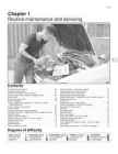
    1·1 Chapter 1 Routine maintenance and servicing 1 Contents Air cleaner element renewal . . . . . . . . . . . . . . . . . . . . . . . . . . . . . . .34 Fuel filter renewal - fuel injection engines . . . . . . . . . . . . . . . . . . . .36 Alternator drivebelt check . . . . . . . . . . . . . . . . . . . . . . . . . . . . . . . .20 Hinge and lock check and lubrication . . . . . . . . . . . . . . . . . . . . . . .31 Automatic transmission fluid level check . . . . . . . . . . . . . . . . . . . . .27 Idle speed and mixture adjustment . . . . .

    Auto õpetus
    ABS Piping Australian Presentation
    92
    ppt

    ABS Piping Australian Presentation

    A Course In the Design of ABS Piping Our Objectives Presented by Geoffrey D Stone FIMechE C.Eng http://waterhammer.hopout.com.au/ Provide an insight into what piping designers need & expect Define the role of the supplier & designer Learn some fundamentals of piping design Discover failure analysis techniques Share experiences of problems A Course In the Design of ABS Piping What We Shall Look at This Week ABS Material Properties Thermoplastic Pipe Design Waterhammer Analysis Typical Applications of ABS Pressure Pipe Some Anticipated Events Stages of the Design Process Representation-Drawings & Specification Calculation-Engineering & Assumptions Visualisation-Presentation of Information Validation-Testing & Commissioning Role of the ABS Pipe Supplier What the Customer Expects Avoid the following: Material Properties Accept design risk for a sale Design Criteria Accept MTO risk Design Guidance What you should do Material take

    Inglise keel
    TOPICS FOR SPEAKING
    28
    doc

    TOPICS FOR SPEAKING

    TOPICS FOR SPEAKING CYLINDER FRAME The cylinder section of the engine consists of a number of cylinder blocks, which are tightened together with the engine frame and the bedplate by means of through- going stay bolts. Two central bores, one at the top and one halfway down inside the cylinder block, enclose the cylinder liner. The upper part of the cylinder block forms part of the cooling water space around the central part of the cylinder liner, whereas the lower part forms the scavenge air space. A central bore in the bottom of the cylinder block encloses the piston rod stuffing box. The bottom is double with a hollow space through which cooling water is circulated. On the exhaust side of the cylinder block there is a circular opening leading into the longitudinal scavenge air receiver of the engine. Furthermore, there is an inlet pipe for cooling and lubricating oil. The cylinder block is provided with cleaning and inspection covers for the cooling water and

    Inglise keel
    2-stroke tuners handbook tuners
    171
    pdf

    2-stroke tuners handbook tuners

    Two-Stroke TUNER’S HANDBOOK By Gordon Jennings Illustrations by the author Copyright © 1973 by Gordon Jennings Compiled for reprint © 2007 by Ken i PREFACE Many years have passed since Gordon Jennings first published this manual. Its 2007 and although there have been huge technological changes the basics are still the basics. There is a huge interest in vintage snowmobiles and their “simple” two stroke power plants of yesteryear. There is a wealth of knowledge contained in this manual. Let’s journey back to 1973 and read the book that was the two stroke bible of that era. Decades have passed since I hung around with John and Jim. John and I worked for the same corporation and I found a 500 triple Kawasaki for him at a reasonable price. He converted it into a drag bike, modified the engine completely and added mikuni carbs and tuned pipes. John borrowed Jim’s cop

    Mootor
    Energy - põhjalik referaat energiast
    62
    doc

    Energy - põhjalik referaat energiast

    SISUKORD ENERGY STORY................................................................................................................4 USES OF ENERGY............................................................................................................. 4 2.1 Uses of energy in homes...............................................................................................5 2.2 Types of energy used in homes.................................................................................... 6 2.3 Energy use in different types of homes........................................................................ 6 2.4 Commercial Energy Use...............................................................................................9 2.5 Industrial and Manufacturing Energy Use..................................................................11 2.6 Transportation Energy Use.........................................................................................12 RENE

    Inglise keele foneetika ja fonoloogia
    Turbo ja kompressor inglise keeles
    2
    docx

    Turbo ja kompressor(inglise keeles)

    Since the invention of the internal combustion engine, automotive engineers, speed junkies and racecar designers have been searching for ways to boost its power. One way to add power is to build a bigger engine. But bigger engines, which weigh more and cost more to build and maintain, are not always better. Another way to add power is to make a normal-sized engine more efficient. You can accomplish this by forcing more air into the combustion chamber. More air means more fuel can be added, and more fuel means a bigger explosion and greater horsepower. A turbo/supercharged engine produces more power overall than the same engine without the charging. Both superchargers and turbochargers do this. The difference between the two devices is their source of energy . TURBOCHARGER When people talk about race cars or high-performance sports cars, the topic of turbochargers usually comes up. Turbochargers also appear on large diesel engines. A turbo can significantly boost an engine's horsepowe

    Jõuülekanne
    Structural Testing Of Homebuilt Aircraft
    8
    pdf

    Structural Testing Of Homebuilt Aircraft

    STRUCTURAL TESTING OF HOMEBUILTS Editor's Note: Alex Strojnik's Aviation articles on laminar flow in in all cases of new designs. He writings and aircraft designs have lightplane design, Alex designed also believes load testing may be in appeared in Sport Aviation many and built a very low drag powered order in a number of instances times in the past decade. A native sailplane, the S-2 (Sport Aviation, involving composite airframes. of Yugoslavia, Alex has very April 1982), which would become While there has been no history of impressive academic credentials. the first homebuilt motorglider in structural failure in composite He holds a degree in electrical engi- which International FAI Silver, Gold homebuilts that have been con- neering, a Ph. D. in aerodynamics .. and Diamond badges would be

    Abimehanismid
    Study of heat transfer coefficient in helical coil
    52
    docx

    Study of heat transfer coefficient in helical coil

    INSTITUTO POLITECNICO DO PORTO INSTITUTO SUPERIOR DE ENGENHARIA DO PORTO CHEMICAL ENGINEERING DEPARTMENT PORTUGAL Marvin Üürike Tallinn University of Technology Faculty of Chemical and Materials Technology Department of Chemical Engineering Estonia ERASMUS PROJECT STUDY OF THE HEAT TRANSFER COEFFICIENT IN A HELICAL COIL Supervisor: Albina Ribeiro Porto 2015 2 Abstract The following work investigates overall heat transfer coefficient of a helical coil and how it changes in different situations. The variables investigated were flow rate inside a submerged helical coil and agitation of the bath. To investigate the change in heat transfer coefficient in different situations, a simple experiment was set up. It consisted of a rectangular isolated tank, which was filled with water, submerged ste

    Kategoriseerimata


    Meedia

    Kommentaarid (0)

    Kommentaarid sellele materjalile puuduvad. Ole esimene ja kommenteeri


    Sellel veebilehel kasutatakse küpsiseid. Kasutamist jätkates nõustute küpsiste ja veebilehe üldtingimustega Nõustun