2-stroke tuners handbook tuners (0)
Jennings: Two-Stroke Tuner's Handbook
Two-Stroke
TUNER’S HANDBOOK
By Gordon Jennings
Illustrations by the author
Copyright © 1973 by
Gordon Jennings
Compiled for reprint © 2007 by Ken
i
PREFACE
ii
Many years have passed since Gordon Jennings first published this manual. Its
2007 and although there have been huge technological changes the basics are still the
basics. There is a huge interest in vintage snowmobiles and their “simple” two stroke
power plants of yesteryear. There is a wealth of knowledge contained in this manual.
Let’s journey back to 1973 and read the book that was the two stroke bible of that era.
Decades have passed since I hung around with John and Jim. John and I worked
for the same corporation and I found a 500 triple Kawasaki for him at a reasonable price.
He converted it into a drag bike, modified the engine completely and added mikuni carbs
and tuned pipes. John borrowed Jim’s copy of the ‘Two Stoke Tuner’s Handbook” and
used it and tips from “Fast by Gast” to create one fast bike. John kept his 500 until he
retired and moved to the coast in 2005. The whereabouts of Wild Jim, his 750 Kawasaki
drag bike and the only copy of ‘Two Stoke Tuner’s Handbook” that I have ever seen is a
complete mystery. I recently acquired a 1980 Polaris TXL and am digging into the inner
workings of the engine. I wanted a copy of this manual but wasn’t willing to wait for a
copy to show up on EBay. Happily, a search of the internet finally hit on a Word version
of the manual. Previous searches had unearthed usable but poor quality .pdf versions that
didn’t print very well.
I have proof read and edited this version and will print and bind a copy for
myself. Although it is not an authentic reproduction it will be a proud addition to my
library. I have to thank the anonymous creator of the file 2-stroke-guide_r2.zip.
I felt I had to share the background and history of the quest. Perhaps it will help
you enjoy this copy and in closing I would like to thank Gordon Jennings for the fine
material and all the effort he put into the original publication. Computers and all the fine
software have taken modifying and tuning two-strokes to a level higher that one could
have imagined in 1973. A lesser work would have surely passed into “Nostalgia
Heaven” long ago.
On page 51 Gordon uses the term “One-Percenter”, the term refers to an
American Motorcyclist association quote “that 99% of motorcyclists were law-abiding
citizens, and the last one percent were outlaws”.
iii
FOREWARD
iv
Only ten years ago the two-stroke engine was widely and quite understandably
thought to be a "reasonable alternative to the four-stroke only when minimum weight and
manufacturing cost were all-important considerations. The two-stroke was recognized as
having substantial theoretical promise, as it delivered a power stroke for each 360 degrees
of crankshaft rotation but the hard reality was that each individual power impulse was too
feeble to amount to much when totaled at the output end of the crankshaft. A very few
engines had begun to appear in which some of the theoretical promise was realized
however, and this encouraged engineers at MZ, Yamaha and Suzuki to persist in their
efforts to wring competitive power output from the racing two-stroke engine. To say that
they were ultimately successful would be gross understatement.
Those engineers were motivated by the need to demonstrate that the two-stroke
engine, per se, was worthwhile -as that would stimulate sales of their companies' ordinary
touring models. My own interest in the two-stroke, which had reached the level of an
obsession by 1963, was generated by comparative poverty. I like to tinker with engines,
and the complexities of the poppet-valve four-stroke make modifications very expensive.
One may think that a change in valve timing would do wonders for a four-stroke's power,
but getting a camshaft made to order costs hundreds of dollars. In contrast, a two-stroke
engine's valve timing may be altered simply by reshaping the holes in its cylinders, and
its power output markedly changed by utilizing inertia and resonant effects in its intake
and exhaust tracts. None of these modifications are costly.
On the other hand, while the two-stroke engine does not commonly require large
dollar inputs to raise its power output, it does require an in-depth under- standing on the
part of the man doing the modifications. In an attempt to acquire that understanding I
began a study of the high-speed, high-output two-stroke engine that has led to the
collection of a minor library of text books and SAE papers. And to an endless series of
experiments, some of them illuminating and many others raising more questions than
they have answered. At this stage I have arrived at more or less satisfactory explanations
for most of the gross phenomena, such as the general behavior of expansion chambers
and port time-area values, and I flatter myself to think that just that much is an acceptable
excuse for writing this book for the guidance of the layman experimenter. If it will not
supply all of the answers it will at least take care of the fundamental problems and
prevent the worst mistakes.
My special thanks to Mr. John Brooks, of McCulloch Engineering, who has done
much to dilute my once pure ignorance (but should not be held accountable for the
residue found herein). Also to the late Henry Koepke, who mistakenly assumed that I
knew something about two-stroke engines and supported my early research; to my old
friend Joe Parkhurst, who started me working on this book nearly ten years ago but never
got it; and finally to Tom Heininger, who wheedled, needled, pleaded, complained and
cajoled until I hammered my file of notes into publishable form.
CONTENTS
v
Preface
.....………………………………………………………………... ii
Foreword ….………………………………………………………………...
iv
Contents
…………………………………….…………………………….... v
FUNDAMENTALS …………………………………………………………….. 1
Predicting Power
…………………………………………………..… 3
Piston Speed
…………………………………………………………... 5
Piston Acceleration
…………………………………………………… 7
CRANK TRAIN ………………………………………………………………. 17
The Piston
…………………………………………………………… 17
Piston Rings
……………………………………………………………. 22
Wristpin/Crankpin Bearings
…………………………………………… 25
Crank Assembly ……………………………………………………………. 30
CYLINDERHEADS …………………………………………………………….. 33
The Combustion Process
……………………………………………. 34
Squish Bands
…………………………………………………………... 37
Plug Location
…………………………………………………………….. 42
Head/Cylinder Sealing ……………………………………………………. 46
EXPANSION CHAMBERS …………………………………………………… 51
The Basic Process
…………………………………………………… 52
Tuned Length
.………………….……………………………………….. 55
Diffuser Proportions
……………………………………………………. 56
Baffle Cones
............................................................................................. 61
Outlet Pipes
............................................................................................. 64
Lead-in Pipes
............................................................................................. 66
Expansion Chamber Design Formula ......................................................... 73
PORT TIMING .................................................................................................... 75
Specific Time-Area
................................................................................. 76
Angle-Area .............................................................................................
80
Time-Area Combinations
..................................................................... 81
Emphasis on Area
................................................................................. 84
Timing Limits ............................................................................................ 85
Rotary-Valve Timing
................................................................................ 88
Porting …......................................................................................................
90
CONTENTS
vi
CRANKCASE PUMPING …............................................................................... 91
Resonance Effects
................................................................................. 92
Carburetor Location
…............................................................................. 94
Crankcase Volume
................................................................................. 95
Reed Valves
............................................................................................. 98
The Rotary Valve
................................................................................. 101
Intake Port Shape
................................................................................. 102
CYLINDER SCAVENGING ............................................................................... 105
Exhaust Port
............................................................................................. 109
Port-Edge Chamfers
................................................................................ 112
Flow Patterns
............................................................................................ 115
Multiple Transfer Ports …............................................................................. 119
Subtleties
............................................................................................. 121
CARBURETION, IGNITION ……...................................................................... 129
The Basic Carburetor ................................................................................. 130
Adjusting Mixture
................................................................................. 134
Ignition Fundamentals …............................................................................. 143
Spark Plugs
............................................................................................. 152
Ignition Timing ............................................................................................. 157
TIPS FOR BIG BORING CYLINDERS ………………………………………. 158
Note: An original manual was scanned, and that .pdf was converted to a MS-Word document. I copied that
document from the site http://edj.net/2stroke/jennings/ and prior to printing for my own use took the liberty
of correcting typos, changing phases, adding some notes and a few quotes from Gorr.
vii
FUNDAMENTALS
1
Throughout this book it will be assumed, inconvenient though that assumption
may occasionally be, that the reader has progressed to at least a superficial knowledge of
the manner in which a piston-type internal combustion engine - with particular reference
to those operating on the two-stroke cycle principle-converts quantities of fuel and air
into useful power delivered at the end of its crankshaft. People who need enlightenment
in that regard will find a wealth of explanatory literature collected on the shelves of any
public library; no real purpose would be served by lingering over the matter here.
Neither will I attempt to instruct you in the elementary mathematics and physics required
to grasp much of what follows, as again the public library is an entirely adequate source
of information. What will be provided is a kind of “state of the art” report about high-
speed, high-output two-stroke engines for laymen-who in most cases do not have access
to the literature (SAE papers, etc.) available to engineers and thus must rely upon
hunches (often wrong) and folklore (almost invariably wrong) for guidance. Many have
learned, to their sorrow, that it is distinctly possible to lavish enormous amounts of time
and money on the two-stroke engine without realizing a return appropriate to the
investment. The information to be provided here will not make you a Kaaden, or Naito;
it will help you to avoid some of the more serious mistakes.
The first serious mistake a layman experimenter can make is to assume that those
who designed and manufactured his particular engine didn't know what they were doing.
In point of fact, the professional engineer knows very well, and if the engine in question
is something other than what the experimenter has in mind, there are excellent reasons:
all engines are compromised, from what you might consider an ideal, in the interest of
manufacturing economy and broad usefulness. For example, ports may derive their shape
as much from what the design engineer intended to be a low scrap-rate casting as from
consideration of flow characteristics. In other words, even something like ports-design
always will be influenced by the demands of mass-production manufacturing. Similarly,
designing for mass-market sales implies that an engine must be agreeable to many
different uses - even though that inevitably means that it will do no single thing
particularly well. In these areas will we find the latitude for “improving” an engine, and
one should always be mindful that the real task is simply to tailor a mass-use product to a
very specific application- and that in the tailoring process one inevitably will incur all the
various expenses the engine's designer has avoided. Hours of labor may be required to
finish rough-cast ports; dollars will be spent correcting other things that are the creatures
of manufacturing economies; power added at maximum revs will be power subtracted at
lower crankshaft speeds, while the increased speeds required to obtain large
improvements in power output will be paid for in terms of reliability.
Two Stroke TUNER’S HANDBOOK
2
Another mistake commonly made, sometimes even by those who have enjoyed
some success in modifying two-stroke engines, is to believe in a kind of mechanistic
magic. Bigger carburetors, higher compression ratios, altered port timings and expansion
chambers often do bring an improvement in power output, but more and bigger is not
magically, instantly better. All must work in concert with the basic engine, directed
toward the particular application, before they constitute a genuine improvement. You
cannot treat them as a voodoo incantation, hoping that if you mutter the right phrases and
stir the chicken entrails in the prescribed manner, your mild-mannered, all-purpose
chuffer will be transformed into a hyper-horsepower fire-breather. With a lot of luck,
you might get that result; the chances heavily are that you won't.
With all the mysticism filtered out, horsepower at any given displacement is
simply a function of average pressure in the cylinder during the power stroke and the rate
at which power strokes occur, minus work absorbed by friction and scavenging. Raise
pressure and/or the delivery rate of the power strokes, or reduce friction and pumping
losses, and the engine's net output will rise. Unfortunately, there are limitations on all
sides: Pressure must be limited because of thermal considerations (and is further limited
by an engine's restricted ability to recharge its cylinder with a fresh air/fuel mixture
between power strokes). The limit for power strokes per unit of time is established by
what is tolerable in terms of crankshaft rotational speeds, and tolerable here is what the
bearings, rod and piston will survive, in inertia loadings, for what you consider an
acceptable service life; the design engineer has already expressed his opinion in this
matter. Pumping losses can be reduced - relative to the mass flow through an engine -
with a properly designed exhaust system, but otherwise are an inevitable and almost
invariable consequence of pulling air from the atmosphere, moving it through the engine,
and out the exhaust port. Some improvement in output may be obtained with reductions
in friction, but the scope for such improvements is very small compared to what may be
accomplished with cylinder pressure and engine speed.
Obviously, pressure in a cylinder will vary continuously throughout an engine's
entire power stroke. Knowing what those pressures may be in a given engine is useful,
but more useful still is knowing what they should and are likely to be, as such knowledge
can keep you from that futile exercise commonly known as flogging a dead horse - and
from believing a lot of lies about how much power various people are getting from their
engines. Engineers have an overall efficiency rating called “brake mean effective
pressure” (bmep), which they calculate by working their way back through torque
readings observed on the dynamometer, the leverage provided by crankpin offset, and
piston-crown area. Thus, bmep says little about peak cylinder pressures (those
measurements being taken with a pressure transducer and oscilloscope) but it is an
excellent relative indicator of performance and highly useful in projecting power output
from a modified engine.
FUNDAMENTALS
3
PREDICTING POWER
An average, well-developed stock engine intended for use in a sports/touring
motorcycle will have a bmep of about 70-psi. It is possible, and I must stress that word
"possible", to raise this to perhaps 115-psi - an improvement of some 64-percent - which
(if accomplished) will yield a 64-percent increase in power output without raising the
engine's operating speed. Similarly, a 64-percent increase in operating speed without a
change in bmep would have the same effect on output. You will see this in the following
formula for calculating horsepower:
33,000
PLAN
BHP
=
Where BHP is brake horsepower
P is brake mean effective pressure, in psi
L is piston stroke, in feet
A is the area of one piston, in square inches
N is the number of power strokes per minute
Obviously, when the values of L and A are held constant, as would be the case
with an engine having a piston displacement at the limit established for a particular racing
class, then increases in power may only be obtained by increasing the values for P and N
- and you will find that in practice it is a lot easier to increase the latter than the former.
As already stated, bmep figures for stock, touring-type engines with flow-
restricting air cleaners and mufflers, and with porting/carburetion compromised in favor
of smooth low-speed running, will be around 70-psi. Typical figures for engines with
porting and other plumbing arranged solely (and effectively) for maximum horsepower at
peak revs would be about 115-psi - with a few small, highly-developed two-stroke
engines operating up at 125-psi. The exact number will vary according to unit cylinder
displacement and the width of an engine's useful power band, but one may reasonably
expect that engines suitable for motocross will fall in the 85>95-psi range - with big
cylinders tending toward the lower figure and small cylinders vice versa. Road racing
engines, tuned to exert a maximum effort over a very narrow speed range, will usually
show a bmep of 100-115-psi, and of course the same remarks regarding the influence of
cylinder size apply. Bimotion © 2000 suggested a BMEP of 11 bar (160 psi) for road
race, 9 bar (130 psi) for motocross and 8 bar (116 psi) for enduro.
These numbers have usefulness beyond the mere satisfaction of vulgar curiosity:
they may be used very profitably to determine an engine's suitability for some particular
application. For example, they shed light on the future prospects of those who are trying
to transform Kawasaki's F-5 “Bighorn” engine, a 350cc single, into a prime-mover
Two Stroke TUNER’S HANDBOOK
4
capable of ending the Yamaha TD-2's absolute domination in road racing. Much has
been made, by the Kawasaki's supporters, of the usefulness of a broader power range
inherent with the F-5's disc-valve induction and the l00cc advantage it gets, over the TD-
2, by having only a single cylinder (this, under the present American Motorcycle
Association rules). Now while it is true that a racing motorcycle having a wide power
band is easier for its rider to manage, and may offer an absolute if very slight advantage
on short, extraordinarily twisty circuits, one must not overlook the fact that the TD-2 has
been blessed with an excellent close-ratio transmission and a number of riders quite
capable of coping with any problems introduced by the need for frequent gear changes.
Viewed realistically, the situation facing any serious challenger to Yamaha's supremacy
is one in which horsepower must be met with horsepower. And what are the Kawasaki's
prospects of developing that kind of horsepower? Let's have a look at the numbers:
Assuming that the man who modifies the Kawasaki F-5 knows his business, but
doesn't have all the development time in the world, (probability favors the latter far more
than the former) then he very likely will arrive at a combination of porting, etc., good for
a bmep of about 105 psi-which is about all that can be expected with a single cylinder of
350cc displacement. To expect more would be to ignore the considerable difficulties in
scavenging efficiently the F-5's large-bore (3.17-inch) cylinder. Further assuming (and as
we shall see later, this assumption is far from safe) that the F-5 engine will remain in one,
working piece for the duration of a longish race with its rider observing a red-line of 9000
rpm, with a power peak at 8500 rpm, then,
BHP =
000
,
33
8500
789
.
7
223
.
0
105
×
×
×
BHP = 47.6
So, a well developed F-5 would deliver 47.6 brake horsepower. How does that
compare with the Yamaha TD-2? With all the years that have gone into the TD-2's
development, and giving due thought to Yamaha's proven expertise in these matters, it
seems safe to assume that this engine would be operating with a bmep of 115 psi at its
power peak- which seems to be at 11,000 rpm. Thus, working from those numbers and
the 250cc Yamaha twin's bore/stroke dimensions of 56mm and 50mm, respectively,
BHP =
000
,
33
000
,
22
81
.
3
164
.
0
115
×
×
×
BHP = 48.0
FUNDAMENTALS
5
Clearly then, those who would try to beat the Yamaha with a Kawasaki F-5 have
taken upon themselves a task of considerable magnitude. The only bright spot in the
picture, for them, is that while they are 0.4 bhp down on the Yamaha (assuming near-
optimum work on their part) they probably will have the advantage in terms of average
horsepower, figured from the moment a gear is engaged - when revs fall somewhat below
those for peak horsepower -until the red-line is reached and it is time for a change to the
next higher gear. There will be no advantage in frontal area, for although the F-5 engine
is narrower than that of the TD-2, the fairing must be wide enough to shroud the rider,
and the minimum width that requires is sufficient to encompass either engine. Moreover,
moving from the theoretical to the practical for a moment, it is highly unlikely that the
Kawasaki could be made as reliable at 8500 rpm as is the Yamaha at 11,000 rpm, and not
because the F-5 engine is badly designed or shoddily constructed. The simple truth is
that any single-cylinder 350cc engine with the F-5's bore/stroke dimensions and red-lined
at 9000 rpm is going to be stressed very near its absolute limit - a limit imposed by the
properties of available materials.
PISTON SPEED
All this asks the question, “How does one determine the limit, with regard to
engine speed?” Unfortunately, establishing this limit with any precision is not only
extremely difficult in terms of the mathematics involved, but also requires data
concerning metallurgy, etc., seldom available outside the record-rooms of the factories
from which the engines originate. Still, there are guide-lines which, if lacking in absolute
precision, do at least have the virtue of simplicity, and will provide an indicator to keep
us away from certain trouble. It is almost impossible to establish the point, in engine
speed, between zero trouble and the possibility of trouble; there is much less difficulty in
determining a red-line between some trouble and nothing but trouble.
A quick and easy method of establishing a limit for crankshaft speed is by
working with piston speed. Actually, with "mean" piston speed: pistons do not travel at
uniform velocity; they move from a dead stop at each end of their stroke, accelerate up to
a maximum speed that often is in excess of 120 mph, and then brake to another complete
stop. For convenience, we use just the mean piston speed and the safe limit for that, for
engines having bore-stroke dimensions within the range considered normal for
motorcycles, is about 4000 feet per minute. And mean piston speed may be calculated
very easily by applying the following formula:
Two Stroke TUNER’S HANDBOOK
6
Cm = 0.166 x L x N
Where:
Cm is mean piston speed, in feet per minute
L is stroke, in inches
N is crankshaft speed, in revolutions per minute
Thus, using again the Kawasaki F-5 engine as an example, with L being 2.68-inches and
N given as 9000, we find that
Cm = 0.166 x 2.68 x 9000
Cm = 4000 ft/min
Here we have a theoretically-predicted limit that seems to agree quite closely with
observable reality in the field: Reports from those actually racing modified F-5
Kawasaki’s indicate that the engine does in fact retain acceptable (within the framework
of that word's meaning in racing) reliability when red-lined at 9000 rpm, and ravels with
horrifying abruptness if pressed further. Of course, it must be stressed here that few
engines, the F-5 not excepted, retain more than marginal reliability at mean piston speeds
of 4000 ft/min, and even this presupposes frequent replacement of the piston and the
crank/rod bearings.
You will be on far more solid ground if your engine is not asked to endure mean
piston speeds above 3500 ft/min. Anything above that takes an engine into the twilight
zone of reliability, and the ground between 3500 ft/min and the near absolute limit of
4000 ft/min is covered with unpleasant possibilities, but these often may be minimized
with the proper selection of materials and lubrication. I should note here that there are
exceptions to this rule among some of the old-fashioned, long-stroke engines, which tend
to have very light (and strong) reciprocating parts relative to their absolute stroke. An
example that comes to mind is the Bultaco 125cc TSS, which had a stroke of no less
2.36-inches (decidedly long for a 125) but which would, in “factory” road racing trim run
up to 11,500 rpm, just like the Yamaha TD-2 (with a much shorter, 1.97-inch stroke), and
that represents a mean piston speed of 4500 rpm. Obviously, Bultaco held the opinion
that the resulting thin-ish margin of reliability was acceptable, but their TSS never was as
predictably trouble-free as Yamaha's TD-2, which at the same crankshaft speed (11,500)
has a mean piston speed of only 3775 ft/min.
While on the subject of bore/stroke dimensions, I would like to say that there is
much in favor of long stroke two-stroke cycle engines in many applications. They are not
superior (as many people seem to think) compared to the present day short-stroke designs
in terms of low-speed torque, as torque is entirely a function of displacement and bmep,
and wholely unrelated to bore/stroke ratios. With a long stroke, there is (at any given
displacement) a reduction in bore, and with it a loss of piston area against which gas
FUNDAMENTALS
7
pressure can exert its force, that exactly balances the loss of leverage in a short-stroke
engine (which is, in turn, compensated by a gain in piston area). The only thing wrong
with the long-stroke engine is that its crankshaft speed is limited by inertia loadings, and
that in turn limits its absolute power potential as compared with the “modern” short-
stroker. On the other hand, it is compensated by having a much more compact
combustion chamber, which makes for more efficient burning, and by lower thermal
loadings on the piston as a result of the smaller crown area into which heat from the
combustion process may soak. Finally, there is an advantage in port area for the long-
stroke design resulting from its relatively large cylinder wall area. This area increases in
the long-stroke engine because displacement rises only in direct proportion to stroke, but
is increased by a factor of 3.1416 (the constant, π) with enlargements in bore. These are
very real advantages, but they are not enough, usually, to prevail against the short-stroke
engine's sheer ability to rev. Crankshaft speed is the only thing subject to much juggling
in the horsepower equation- and is a far more potent factor in determining power output
than the relatively slight improvements in bmep obtainable with the marginally better
combustion chamber and porting in the long-stroke engine. A 10-percent improvement
in our Kawasaki F-5 engine's bmep (a large improvement indeed) would raise its output
to 52.3 bhp; leave the bmep unchanged, but shorten the stroke and spin it 11,000 rpm and
you would have 61.3 bhp. There is indeed no substitute for revs.
PISTON ACCELERATION
Sadly, while there is no substitute for revs, there are plenty of barriers: piston
speed is one, as was already noted. But that is a rather indirect limit, as it ignores the fact
that it is not speed so much as all the starting and stopping of pistons that does the
damage, or at least the worst of any damage. The acceleration forces generated by the
starting and stopping are felt even in an engine's main bearings, but they are at a peak in
the connecting rod and piston and have a particularly disastrous effect on the latter, as
any attempt to make a piston stronger is apt also to make it heavier-which aggravates the
very situation the strengthening of the piston should improve. Even so, an engine's true
Achilles heel, the problem that may most strongly resist solution, often is the disastrous
effects piston acceleration may have on the piston's rings.
It often is thought, and quite wrongly, that rings maintain a seal between the
piston and the cylinder's walls simply through their properties as springs. A little thought
should convince you that such cannot be the case, for most rings, compressed in the
process of installation, press outward against the cylinder with a force amounting to about
30-psi. Gas pressure in that cylinder may easily exceed 750-psi, and it should be obvious
that a 30-psi force will not hold back one circa 750-psi. Still, equally obviously, piston
rings do form an effective seal. How? Because they get a lot of help from the cylinder
Two Stroke TUNER’S HANDBOOK
8
pressure itself: gas pressure above the ring forces it down against the bottom of its groove
in the piston, and also (acting behind the ring, in the back of the groove) shoves it out
hard against the cylinder wall. Thus, in the normal course of events, sealing pressure at
the interface between cylinder wall and ring always is comfortably higher than the
pressure it must hold back.
This very desirable situation will be maintained unless something happens to
upset things, and most-insistent among the several “something’s” that may intrude is
excessive piston acceleration. When piston acceleration exceeds the sum total of gas
pressures holding the ring in place, the ring will lift upward (as the piston nears the top of
its stroke, and is being braked to a halt). Instantly, as the ring lifts, the gas pressure
previously applied above and behind is also applied underneath the ring, at which point
its inertia takes over completely and the ring slams up hard against the top of its groove.
This last action releases all pressure from behind the ring, leaving it entirely to its own
feeble devices in holding back the fire above, and as its 30-psi outward pressure is no
match for the 750-psi pressure in the upper cylinder, it is blown violently back into its
groove. The ring's radial collapse opens a direct path down the cylinder wall for the high
temperature and pressure combustion gases - but only for a microsecond - for the action
just described instantly applies gas pressure once again behind the ring and that sends its
FUNDAMENTALS
9
snapping back into place against the cylinder wall. Unhappily, it cannot remain there, as
gas pressure immediately bangs it back into its groove again - to repeat the process over
and over until the piston is virtually stopped and the ring's inertia is no longer enough to
counter gas pressure.
The net result of all this activity is that over the span of several degrees of crank
rotation, immediately preceding the piston's reaching top center, the ring will be
repeatedly collapsed radially and at the same time hammered hard against the top of its
groove. Understandably, the ring is distressed by this, as it not only receives a fearful
battering but also is bathed in fire while being deprived of the close contact with piston
and cylinder that would otherwise serve to draw off heat. Equally damaging is that the
piston is having much the same problem, with high-temperature gases blowing down past
its skirt to cause overheating, to burn away the film of oil between itself and the cylinder
wall, and with its ring, or rings, all the while trying to pound their way up through the
piston crown. A mild case of what is quite accurately termed “ring flutter” eventually
results in the destruction of the ring and sometimes the dimensional integrity of its
groove; a more serious case is certain to lead rapidly into lubrication failure, overheating,
and piston seizure. Fortunately, this drastic problem can be avoided, thanks to the work
of the researcher Paul de K. Dykes, whose investigation of the ring flutter phenomenon
yielded most of what we know about it - and who invented the flutter-resistant ring that
bears his name. Dykes showed us the cause of ring flutter, and engineers' understanding
of the cause is reflected in their designs of the modern piston ring, which is very thin,
axially, with a very considerable width, radially. Thus, gas pressure bears down on a
large surface, providing an equally large total down-force, but is opposed by a relatively
small upward load as the ring, being thin, is light and in consequence has little inertia.
Still, even with very thin rings, flutter will occur if inertia loadings are high enough. To
settle the question, with regard to any given engine, apply the following formula for
determining maximum piston acceleration:
G max =
+
×
A
2
1
1
2189
L
N2
Where G max is maximum piston acceleration, in feet per second squared
N is crankshaft speed, in revolutions per minute
L is stroke, in inches
A is the ratio of connecting rod length, between centers, to stroke
Two Stroke TUNER’S HANDBOOK
10
To illustrate how high these forces may sometimes be, let's use as an example the
Yamaha TD-2, using 11,000 rpm for N. The formula tells us that at that speed, maximum
piston acceleration will be (with the answer rounded off by my slide rule; I'm too lazy to
do it all with paper and pencil) no less than 135,000 ft/sec2. Now if you will recall for a
moment that the acceleration of gravity is only 32 ft/sec2, it will be clear that the load on
the Yamaha's pistons - and thus on its rings - is very high indeed. But is the loading high
enough to make the Yamaha's rings flutter? Obviously, it is not, as the engine remains
not only reliable but crisp in comparatively long races. The limit, for the TD-2 engine, is
slightly higher than 135,000 ft/sec2 - but not much higher, as you will see in the
following table listing ring thicknesses and the accelerations at which they begin to
flutter.
For rings having a
0.125-inch thickness, 40,000 ft/sec2
0.094 “
“ 53,000 ft/sec2
0.063 “
“ 80,000 ft/sec2
0.047 “
“ 106,000 ft/sec2
0.039 “
“ 138,000 ft/sec2
The Yamaha, with rings having a thickness of 1mm, or 0.039-inch, and a
maximum piston acceleration of 135,000 ft/sec2 at 11,000 rpm, would seem to be
operating very near the limit - as indeed it is. But it probably is not quite as near the limit
as the numbers suggest, for a racing ring (with its exaggerated thickness/width cross-
sectional aspect) is somewhat less subject to flutter than a ring made for application in a
touring engine. Still, the numbers given are fairly close for rings with normal-range
proportions, and if you have an engine with rings for which flutter is predicted at 80,000
ft/sec2 and intend using crankshaft speeds that would raise maximum piston acceleration
to something more like 100,000 ft/sec2, then I strongly urge you to fit new pistons with
thinner rings. You may interpolate between the figures given to find the safe acceleration
levels for ring thicknesses not listed.
There are piston rings that resist very strongly piston acceleration's efforts toward
making them flutter. The best known of these is the Dykes-pattern ring, which has an L-
shaped cross-section and fits into a similarly-shaped groove in the piston. The Dykes
ring is made flutter-resistant by the fact that its horizontal leg fits quite closely in its
groove, as compared to clearances around the vertical leg, and therefore even if
acceleration lifts the ring it cannot lift high enough to close off the pressure behind the
ring's vertical leg. In consequence, the ring's sealing abilities are maintained at
accelerations that would be the undoing of rings in the conventional rectangular-section
pattern. However, the Dykes ring's ability to maintain a seal does not free it of all the
unpleasantness attending too-high piston acceleration: while it may seal under those
FUNDAMENTALS
11
conditions, it is still being rattled about vigorously and if the rattling continues long
enough, the Dykes ring, and the groove trying to restrain it, both become badly battered.
At that point, its ability to seal vanishes and mechanical failure of the ring, piston, or
both, follows very closely. Bultaco has long used Dykes-pattern rings, as have certain
others, but most manufacturers prefer rings that do not require such careful and intricate
machining. There are other flutter-resistant rings, and many excellent reasons for using
rings of conventional configuration, but these details are discussed elsewhere in this book
and in greater depth than would be appropriate here.
After establishing all these mechanical limits, with regard to piston speed and
acceleration, and after deciding how much power you are likely to get from a particular
engine, you should subject the engine to a complete survey. This would include the
measuring of port heights and widths, combustion chamber and crankcase volumes, and
charting piston travel against crank rotation. This last effort may at first seem rather
pointless, but as your work progresses you will find that the chart, which will show
almost but not quite a sine curve, provides an instant readout between degrees at the
crankshaft and the position of the piston from top center that is most useful. It will tell
you, for example, how much to raise the top edge of an exhaust port to make a given
change in timing, and how much to trim from the piston skirt (in a piston-port engine) to
Two Stroke TUNER’S HANDBOOK
12
get the intake period you want - or think you want. The chart also will provide you with
all the mean port-open points, and it will provide an exceedingly useful relationship
between ignition timing expressed in degrees and in piston travel from top center. You
may devise your own methods for deriving all this information according to your
preference and resources; I have explained my own techniques elsewhere in this text, in
the appropriate chapters.
An item that must be included in any discussion of the two-stroke cycle engine's
basics is general gas dynamics. You can get information on the subject at your local
library, but the applicable particulars are likely to be widely scattered there, so I will
cover the subject in brief here. The manner in which what follows applies at specific
points throughout the engine and its related plumbing will be covered later, but you
should know a few of the fundamentals now and thus save me from becoming
unnecessarily repetitious later.
One thing you must know, for example, is that the air moving through the engine,
a mixture of gases, has many of the properties of a fluid. It even has the ability to “wet” a
surface, and has viscosity, which means that air will cling to all surfaces within an engine
in a layer that moves hardly at all no matter what the midstream velocity may be. This
boundary layer's depth is influenced by gas temperature, and by the temperature of the
surface on which it forms, as well as by the shape of the surface. Please understand that
the layer is not solid; it is “shearing” with general flow throughout its depth – which may
be as much as 0.100-inch - with movement increasing as to distance from the surface on
which it is formed. And as close as 0.020-inch from the surface, flow may still be in the
order of 80-percent of that in midstream, which means that the restriction formed by the
boundary layer is not very great. Nonetheless, it is there, and it accounts for such things
as round ports having less resistance to flow than square ports, area for area, and for the
ability of a single port to match the flow of a pair of ports of somewhat larger area. It
also accounts for the fact that flow resistance increases in direct proportion with the
length of a port, and much of the resistance resulting from the shape of a particular port is
due to that shape's creating a thick boundary layer, which becomes literally a plug inside
the port.
Generally speaking, boundary layers will be held to minimum depth on surfaces
that “rise” (relative to the direction of flow) and gain in thickness on any surface that falls
away. Thus, an intake trumpet (velocity stack), for example, should be tapered in slightly
from the inlet end to the carburetor-by perhaps 2-3 degrees - in the interest of holding
boundary layer thickness to a minimum. In that configuration, it will have appreciably
less resistance to flow than a straight, parallel-wall tube. Similarly, transfer ports should
diminish in cross-sectional area from their entrance in the crankcase toward their outlet in
the cylinder.
FUNDAMENTALS
13
These gases also have inertia: once set in motion they tend to remain in motion;
when at rest they resist all efforts to get them moving. In practice, this means that there
always is a lag between the intake port's opening and the movement of air in the intake
tract. Fortunately, this lag can be amply compensated toward the end of the intake
period, when the pressure inside the crankcase has risen to a level that should push part of
the charge back out the port-but cannot because of the effect of inertia on the incoming
gases. Inertia also has its effect on the flow of gases through the transfer ports and out
the exhaust system, but I will deal with that while treating those subjects separately.
These inertia effects are useful, but difficult to manage as something apart from
other processes occurring as the engine runs. For example, intake tract length usually is
established more with an eye toward resonances than inertia, and its diameter set by the
flow rate required by the carburetor to meter properly - balanced against the resistance
that attends high gas velocities. Therefore, virtually the only thing we can do about
inertia effects is to attempt to find the intake timing that will make maximum use of those
provided by an intake system proportioned mostly to suit other requirements.
Resonances are another matter. Sound waves will travel through any elastic
medium, such as air, and in their passage they pull together or force apart molecules, just
as the similar energy waves traveling through the ocean pull the water into peaks and
troughs on its surface. And, as in the ocean, the waves move steadily onward away from
their source but the transmitting medium does not. Take, for example, the activity
surrounding a single condensation, or positive-pressure wave, as it moves through the air.
In its center, molecules have been pulled together, condensed, but as it travels it releases
those molecules and compresses others as it reaches them. In the same manner, a
rarefaction, or negative-pressure wave, pushes molecules apart. Both waves behave in a
curious, but useful way when confined in a tube and the effects of inertia are mixed with
them. For one thing, they will be reflected back when reaching the end of the tube -
whether that end is open or closed. But at the tube's open end, the wave changes in sign:
a condensation is inverted and becomes a rarefaction, and vice versa; at the closed end,
the wave will be reflected, but retains its sign.
How is all that useful? For example, in the intake system the opening of the
intake port exposes the crankcase end of the tract to a partial vacuum, and that in turn
sends a rarefaction shooting off toward the opposite, atmospheric, end of the tract. It
travels out to the intake bell, inverts in sign to become a condensation, and instantly
moves back toward the crankcase - to arrive there as a clump of compressed molecules,
which surge into the crankcase to be trapped, if the piston then closes the intake port, as
part of the scavenging charge. That effect, over-layed with inertia in the inrushing gases,
makes all the difference in getting the job of charging done in two-stroke engines - which
provide only an absurdly short time for such chores.
Two Stroke TUNER’S HANDBOOK
14
How short a time? That is at the same time one of the least complicated and most
depressing calculations you can perform. Let us consider the Yamaha DT-1, which in
fully developed configuration had an intake duration of 160-degrees, a transfer duration
of 123-degrees, and an exhaust duration of 172-degrees. Yamaha claims a power peak at
7000 rpm. Let's have a look at the actual time, in fractions of a second, available for the
completion of these functions. To arrive at these times, use the following formula:
360
N
60
T
θ
×
=
Where T is time, in seconds
N is crankshaft speed, in revolutions per minute
θ is port open duration, in degrees
(This formula can be abbreviated to
6
N
T
×
= θ )
Thus, to find T for the 160-degree intake duration,
sec
0038
.
0
360
160
7000
60
T
−
=
×
=
.
With application of the same formula to the transfer and exhaust periods, we find
that the former is open 0.0029-second, and the latter open 0.0041-second. Even the
longest of these, the exhaust-open duration, is only 41/10,000-second, and that is not very
much time in which to empty exhaust gases out of the cylinder. Actually, that particular
process is substantially finished in the 29-degrees, or 0.0007-second, between exhaust-
and transfer-opening. In that short period, pressure in the cylinder must fall to something
very near atmospheric, or the exhaust gases would force their way down into the
crankcase through the transfer ports. Of course, the exhaust gases are provided quite a
large aperture by means of which they may make their escape, and that they do so,
successfully, is less remarkable than the fact that the fresh charge compressed in a two-
stroke engine's crankcase is able to make its way through the far more restricted transfer
ports, propelled by a far lower pressure, to refill the cylinder in the extremely brief
moment available. It seems nothing short of astonishing that this recharging operation is
accomplished in the 0.0027-sec provided by the Yamaha DT-1's 114-degree transfer
period; that the same process takes place in a Yamaha TD-2 engine in only 0.0017-sec
appears a minor miracle. Obviously, divine intervention is not really a factor in the
functioning of two-stroke engines, and cylinder recharging is possible simply because the
process gets a lot of help from the activities of the exhaust system, gas velocities through
the transfer ports have a mean value in the order of 300-ft/sec, and the cross-sectional
FUNDAMENTALS
15
areas of the ports involved are relatively large as compared with the volume of gases to
be transferred.
As it happens, it is possible to calculate correct combinations of port-open times
and port areas for any motorcycle engine, at any engine speed. The maximum safe speed
for any engine is also calculable, as explained earlier in this chapter, along with
expansion chamber dimensions, carburetor size and many other factors influencing both
maximum power output and overall power characteristics. It should be noted here that
none of the values derived purely from calculations are necessarily optima, and fine
adjustments must always be made experimentally, but it is far better to employ the simple
formulae presented in the chapters to follow than to attempt a purely-experimental
approach. The mathematics involved are not terribly complicated, though sometimes the
arithmetic is laborious, and you can use paper and pencil to arrive at a basic engine/pipe
combination that will be very near the optimum. Much nearer, in fact, than would be
obtained by even the most experienced tuner's unsupported guesswork, and near enough
to a fully developed configuration to minimize the outlay of time and money entailed in
the building of a racing engine. You start by determining, mathematically, an upper limit
for engine speed, then use more math in establishing a maximum for piston-ring
thickness, in establishing all the port dimensions to suit the projected engine speed, in
selecting a carburetor, and in designing an expansion chamber. Suitable values for
compression ratios, both primary and secondary, are provided in the chapters dealing
with crankcase pumping and cylinder heads, respectively, and with the rest of the
material included in this book it all adds up to being a fairly complete engine redesign
manual for the two-stroke engine-fixated “tuner”. My own experience indicates that
engines built along the lines suggested here never fail to deliver high specific horsepower
(which is more than may be said for any cut-and-try system) even without the benefit of
experiment-indicated adjustments. I dislike guesswork, have made a serious effort to
eliminate it from my own projects, and am hopeful that the lessons learned - and outlined
in this text - will reduce the generally high level of guesswork among most
experimenters. If I have forgotten to cover anything, the omission is inadvertent, because
my distaste for Speed Secrets is even greater than for guesswork. There is only one
“Secret” in the game: “To know what you are doing, and to do it thoroughly.”
Two Stroke TUNER’S HANDBOOK
16
THE CRANK TRAIN
17
As was noted in the chapter of this book dealing with basics, power output from
an engine of any given displacement is a function of gas pressure in the cylinder during
the power stroke, and the number of power strokes per unit time. Implicit therein is the
suggestion that the horsepower ultimately to be had from an engine has little to do with
port shapes and port timings, exhaust systems, carburetion or indeed any of the things on
which our attention usually is fixed. Why? For one thing, increases in gas pressure bring
corresponding increases in heat flow into the piston - and no high-output two-stroke
engine can operate beyond its thermal limit. Similarly, you cannot increase the rate at
which power strokes occur without increasing crankshaft speeds, with increases in this
direction sooner or later taking you beyond the engine's mechanical limit. The
horsepower you ultimately will extract from any given engine depends therefore very
directly upon your ability to expand those thermal and mechanical limits to the greatest
extent possible, and only then to make the most of the territory thus gained.
THE PISTON
For a very long time subsequent to Dugald Clerk's creation of the two-stroke
engine, the thermal limit was the only limit, but it was enough to hold power output from
such engines to extremely modest levels. Then, as now, it was primarily a limit imposed
by available piston materials. Cast-iron has its advantages in terms of wear resistance,
hot-strength and low thermal expansion rates, and it was used quite frequently in the low
speed engines of years past. Unfortunately, iron is heavy, and heavy is the last thing you
want in a piston - which in modern engines is subjected to accelerations well in excess of
100,000-ft/sec2. Aluminum, used as the primary constituent in virtually all piston alloys
today, is conveniently light, but disagreeably insists on melting at much lower
temperatures than that of the fire to which it is directly exposed. Moreover, it loses
strength very rapidly with increases in temperature above ambient, so that piston failures
do occur at crown temperatures well below the material's melting point. Finally,
aluminum is a high expansion-rate metal, which makes a piston made of it a variable-
clearance fit in any cylinder. But aluminum is a very light metal, and that alone was
enough to recommend it for use in pistons, even though the drawbacks listed were
enough to severely limit the specific power outputs attainable with two-stroke engines for
a long time.
Aluminum-based piston alloys improved slowly over the years, with the addition
of small percentages of, say, copper, to improve their hot-strength, but it was not until
means were found to add considerable amounts of silicon that large improvements were
made. Today, the best piston alloys contain between 15- and 25-percent silicon, and this
addition has all but transformed the “aluminum” piston. Add mixtures of silicon in
excess of 15-percent not only drastically reduce aluminum's expansion rate, they also
Two Stroke TUNER’S HANDBOOK
18
affect a proportionate increase in hot-strength and improve the piston's wear-resistant
properties. In all of these respects the improvement is large enough to almost exactly
equal the percentage gains in horsepower during the years in which aluminum-silicon
alloys have been in use. I am inclined to think that most of what we consider to be
“modern” improvements in two-stroke engine design - with particular reference to
expansion-chamber type exhaust systems -might have been applied as much as fifty years
ago had good pistons been available. There was little point in such development work
without the aluminum-silicon piston; aluminum or aluminum-copper pistons would melt
at specific power outputs well below what we now consider only average.
With all that, high silicon-content piston alloys still are not universally employed.
As it happens, such alloys do have their disadvantage, which is that they are difficult to
manufacture. Just casting pistons of aluminum-silicon alloy is a task for specialists using
specialized equipment; machining the raw castings into finished pistons is an even more
formidable task. You may encounter this last difficulty if you have occasion to modify a
cylinder cast from the material in question - and you will find that it blunts cutting tools
of any kind with remarkable rapidity. For you, that will be an inconvenience; for the
mass-producer of pistons it is a disaster, as the need for frequent re-sharpening of tool
bits entails losing output from his machinery while such repairs are made, and it means
the expense of the man-hours required for the repairs. Thus, the manufacturer has every
reason to restrict the silicon content of the piston alloys he uses to the minimum required
by the use to which his engines will be put, which is the reason why Yamaha, for
example, uses different alloys for touring and racing pistons.
In point of fact, the Japanese seem to manage high silicon-content pistons better
than anyone else, which may well account for their notable superiority in coaxing power
from two-stroke motorcycle engines. All of the major Japanese manufacturers employ
piston alloys in their touring engines having percentages of silicon high enough to be
considered “racing only” in much of the rest of the world. And, sad to say, many of the
“racing” pistons being offered by speed equipment manufacturers are inferior in this
regard to the ordinary off-the-shelf parts you'll find at your local dealer in Japanese
motorcycles. For that reason, I am inclined to use either stock or “GYT-kit” pistons
when I am working with engines carrying a “made in Japan” label, rather than waste my
money on a specialty replacement. There are, of course, exceptions to this rule, which
evolve principally around ring widths, and I will deal with that in due course.
Unless you happen to be a piston manufacturer, there isn't much you can do about
piston alloys, beyond seeking out pistons having a high silicon content. Neither is there
anything you can do about piston shape - which is most unfortunate, because a piston is
not, as it first appears, simply cylindrical. Even with the use of aluminum-silicon alloys,
pistons do expand as they are heated, and they do not expand at all evenly. The greatest
increase in diameter will occur up at the crown, because that is both the area of maximum
THE CRANK TRAIN
19
mass and highest temperature. So there must be more clearance, measured cold, up at the
piston's crown than is required down around the lower skirt. In fact, clearances vary
continuously from the piston's crown to the bottom of its skirt - and from side to side, as
the piston is elliptical rather than round. Someday, someone may be able, with the help
of a computer, to actually calculate all the clearances and ellipse ratios involved; for the
present they are decided in a process of trial-and-error by even the most experienced of
manufacturers.
Presumably, you will not have the facilities to alter whatever shape your engine's
piston(s) may have, but you can vary running clearances by changing cylinder bore
diameter. The problem here is one of “How much?” and I regret to say that it is a
problem for which there is no convenient solution. Clearances, measured at the piston's
maximum diameter, across its thrust faces, may vary from about 0.002 to as much as
0.007-inch, depending on: the shape and composition of the piston itself; the absolute
cylinder bore diameter; the material from which the cylinder is made, as well as its
configuration; and the thermal loadings to which the piston will be subjected - which will
themselves vary according to gas pressure, fuel mixture, cylinder configuration and the
vehicle's rate of motion. Many people have expressed great faith in rules relating
Two Stroke TUNER’S HANDBOOK
20
clearance to cylinder bore diameter; I have not found the choice to be that simple. If
there is a rule, it would be that you can add perhaps 0.0005- to 0.001-inch to the
clearance recommended by your engine's maker, but even this is a gross over-
simplification and I mention it only because it is somewhat better to have too much
clearance than too little. In the former, the excessive clearance adversely influences heat
transfer from the piston to the relatively cooler cylinder walls and may lead to any of the
several unpleasantries associated with overheating the piston, which range from a
tendency for oil to become carbonized in the ring grooves, to the appearance of a large
hole in the piston crown. Too little clearance will reveal itself in the form of scuffing, or
outright seizure - unless the piston is only marginally too tight, in which case the only
symptom of distress will be a power loss in the order of 2- to 3-percent.
Often, in modified engines, you will find that the straightforward increase in
overall piston clearance by slightly enlarging the cylinder bore is not a complete answer.
If the manufacturer has done his work properly, his pistons will, as they expand with
temperature, assume a round shape when the engine is hot. Your problem will be that
with the modifications you have made, more heat will be forced into the piston's crown,
raising its temperature above the level anticipated by the manufacturer, which results in a
completely different set of temperature gradients down the length of the piston.
Specifically, while the whole piston will assume a diameter slightly larger than that
planned for by its maker, the area around the crown will “grow” more than the rest. It
will thus be impossible to correct for the altered conditions simply by honing the cylinder
bore larger, for if you enlarge the bore enough to provide running clearance for the top of
the piston, its skirt will be given too much clearance (leading to rocking, and trouble with
the rings). In such cases, which are not the exception, but the rule, the solution is to
machine what is called a “clearance band” around the top of the piston. Usually, this
band will extend down from the crown to a point about 0.125-inch below the ring groove,
or grooves, and the piston's diameter reduced by perhaps 0.002-inch over the entire
band's width. Although the clearance band is not a particularly clean solution to the
piston-expansion problem, it is one that can be applied by anyone with access to a lathe,
and it has one advantage over the generally more desirable “pure” contouring of the
piston: if a piston with a clearance band seizes partially, aluminum will not be smeared
above and below the ring groove - an event which will lock the ring in its groove and
upset its ability to seal against gas pressure, In practical terms, this means that the
clearance-banded piston will absorb a lot of punishment before it is damaged sufficiently
to cause retirement from a race.
Excessive deep clearance bands must be avoided, for they expose the sealing ring
to too much heat, and heat has a devastating effect on the service life of a piston ring.
But for these effects, there would be every reason to locate the ring as close to the piston
crown as is mechanically possible, because we would then obtain the cleanest opening
THE CRANK TRAIN
21
and closing of the ports; with the ring in its usual position, about 0.200-inch below the
piston crown, there is a tendency for gases to leak down the side of the piston, and the
port-opening process thus becomes more gradual than is desirable. The effect is slight,
but it is there, and for that reason ring location always is a matter of juggling the
conflicting requirements of keeping the ring cool, and obtaining sharp, clean port-
opening characteristics. And in most instances, the balance of this compromise will be in
favor of the former, for an overheated ring quickly fails. The cause of this failure is
twofold: first, excessively high temperatures effectively anneal the ring, and it loses its
radial tension; second, an overheated ring warps like a potato chip, and no longer
maintains close contact with the bottom of its groove. In both of these cases, the ring's
ability to seal is reduced, which allows fire to start leaking down past the ring, and that
further raises its temperature -starting a cycle that soon results in outright ring failure.
The single exception to the unpleasantness just described is the L-shaped “Dykes”
ring, which also is excepted from the immediate effects of ring-flutter (described
elsewhere). A number of engines have been fitted very successfully with Dykes rings
located right at the tops of their pistons, and the dire effects of excessive heating are
avoided because the Dykes ring's vertical leg has enough area in contact with the cooler
Two Stroke TUNER’S HANDBOOK
22
cylinder wall to draw away heat faster than it can be added by the ring's contact with
high-temperature gases. At least, that's the way the situation can be, if everything is
right. On the other hand, it is worth remembering that many users of Dykes-pattern rings
have been forced to fabricate them from stainless alloys to overcome temperature related
troubles, and even then have experienced problems with oil carbonizing in the ring
grooves. Probably the best thing to be said for Dykes-pattern rings from the
experimenter's viewpoint is that they can be used to overcome the problem of using stock
pistons at very much higher than stock crankshaft speeds. If, for example, you would like
to use the stock piston, but cannot because it has been grooved for rings 2.0mm thick and
you must use 1.5mm rings to avoid ring flutter, you can simply cut a new groove at the
top of the piston for a Dykes ring and the problem is solved -unless you encounter some
of the other difficulties just discussed.
PISTON RINGS
Of all the problems that can be experienced with a modified engine, those
connected with the pistons' rings are the most insidious. Borderline sealing failures can
send fire shooting down along the pistons' sides to cause seizures and/or holing of the
piston crown that appear to be the result of lean mixture, excessive ignition advance or
too-high compression, but are not. These failures are, I suspect, much more frequent than
is commonly supposed, for the 2.0mm rings that have become almost standard will begin
to flutter when piston acceleration rises above about 60,000 ft/sec2 and it is entirely too
easy to exceed that limit with a modified touring engine. Therefore, I would again urge
you to do your homework before starting a development program with any engine. A
formula for predicting the onset of ring flutter is provided in the chapter headed,
“Fundamentals”, and you may save yourself a lot of grief by determining your engine's
red-line with paper and pencil instead of through experimentation. At the same time, I
must caution you against simply assuming that very narrow rings are an advantage in all
engines. In fact, there is no detectable power difference between the standard 2.0mm
ring and the “racing” 1.0mm ring below 7000 rpm, and the wider ring has the advantage
of better durability right up to the point where piston acceleration starts it fluttering.
Neither is there any advantage, below 7000 rpm, in the use of single-ring pistons. Above
that level the lower friction of the single-ring piston begins to make a difference, but in
the lower speed ranges you may as well use two-ring pistons and take advantage of their
“second line of defense” capability.
Selection of ring-type will usually have been made for you by the piston
manufacturer, and my advice is that you do not try to improve upon his judgment, which
will be almost impossible in any case. You cannot, obviously, re-machine a piston made
for 2.0mm rings to take 1.0mm rings -unless you cut a new ring groove above the
THE CRANK TRAIN
23
existing grooves, and that would position your ring perilously close to the piston crown
and almost certainly lead to immediate ring failure. The only way around this is to fit a
Dykes-pattern ring, right up at the piston crown - as was noted previously. Such
modifications can be very successful, if you have the right ring for the application and cut
the groove correctly for the ring, but I cannot recommend the procedure simply because
there is so much room for error. In general, I think it is far better to replace the stock
piston with one fitted with thinner rings - even if the replacement piston is cast of
somewhat inferior material, as is often the case. After all, the best of pistons will fail if
its rings are not suited to the job it is being asked to perform. On the other hand, rings of
less-than-desirable material will perform very well in racing applications if replaced
frequently, and if they have not been crudely finished. Much of the ring's ability to
function is related to this latter aspect. The ordinary cast-iron ring is fragile, and will
shatter very quickly if allowed to flutter, but it will perform entirely satisfactorily if its
lower surface is smooth and true, and seals against the bottom of the ring groove. Rings
made of nodular cast-iron have the same wear-resistant properties, and are vastly
stronger, for which reasons this material is almost universally used. Surface coatings,
ranging from chromium to Teflon, are often applied to the piston's ring's face, to improve
service life and /or prevent scuffing during break-in.
Ring sticking is a problem to be faced with all high-output two-stroke engines.
Carburized oil may lock the ring in its groove after a remarkably short period of running
if the ring lacks sufficient vertical clearance (usually, from 0.0015- to 0.0040-inch) or if
the ring is located too near the piston crown. More frequently, the problem stems from
the oil being used for lubrication, and it is most unfortunate that the very oils providing
the best lubrication are the ones most likely to cause ring sticking. Castor-based oils,
particularly, will build up thick layers of varnish inside the ring groove, unless the oil
contains a considerable percentage of detergent chemicals.
Apart from the L-section Dykes ring, most piston rings have a basically
rectangular cross-section, but you will find many minor variations on this arrangement.
Currently very popular is the “keystone” ring, which has a tapered section, with either the
upper or lower surface, or both, sloping away from the ring's outer face. The reason for
this primarily is to keep the ring and its groove scrubbed free of carbon and varnish. In
four-stroke engines the rings are free to rotate, and do, and their rotation performs this
scrubbing. Two-stroke engines nearly always have their rings pinned, to prevent them
from rotating and the ring's ends from springing out and becoming trapped in a port.
Hence, the need for some other form of scrubbing action. Seldom is the taper in a
keystone-type ring more than 7-degrees, and it is all too easy to attempt installing one of
them upside-down, so you should give particular attention to the ring's markings. Such
markings vary in kind, but without exception they will be on the ring's upper surface.
Two Stroke TUNER’S HANDBOOK
24
Another point of trouble can be the ring's locating pin, and if you encounter
difficulties with locating pins working loose, the source of the trouble nearly always will
be in the exhaust port. The racing engine's very wide exhaust port (width representing, in
extreme instances, up to 70-percent of cylinder bore diameter) leaves a lot of the ring's
diameter unsupported when the piston is down in the lower half of the cylinder, which
allows the ring to bulge out into the port. Making the port opening oval and chamfering
its edges will prevent the ring from snagging, as these things ease the ring back into its
groove as the piston sweeps back upward. However, while the ring may not snag on the
port, it does get stuffed back into its groove fairly rudely, and that may have a very bad
effect on the locating pin: On most two-ring pistons, the locating pins are positioned
adjacent to the areas of blind cylinder wall between the intake and transfer ports -placed
about 90-degrees apart - to provide a long path for gas leakage. Thus, when the ring
bulges out into the exhaust port and then is stuffed back, the end of the ring is pushed into
hard contact with the pin, and after a sufficient number of hard blows (and these
accumulate rapidly at, say, 10,000 rpm) the pin begins to loosen and it will gradually
enlarge the hole in which it is inserted enough to work completely loose. Then the ring is
free to rotate, and it quickly works its way around to catch the end in a port. At risk of
seeming immodest, I will admit to having isolated this problem for Yamaha several years
ago and today that firm's racing engines have pistons with locating pins positioned 180-
THE CRANK TRAIN
25
degrees from the exhaust port. Touring engines, which have much narrower exhaust port
windows and thus treat their rings more gently, usually benefit from having their two
rings' end-gaps placed more nearly on opposite sides of the piston, as described before.
In some racing applications, the standard rings are adequate to the engine speeds
anticipated, but overall performance may dictate a much wider-than stock exhaust port.
Then, the “offset” ring-locating pin may prove prone to precisely the sort of loosening
and subsequent failure described in the preceding paragraph, which will lead you into a
piston modification that can be very tricky: installing a new locating pin in the back of
the ring groove. This gets tricky because in many cases the pin will be half-in, half
above, the ring groove and it is impossible to drill the hole for a new location after the
groove is machined. Impossible, unless you cut a small piece of aluminum to exactly fit
the ring groove, filling it flush, in which case you drill your hole half in the piston and
half in the filler piece. Then you remove the filler and your hole is ready for the pin -
which introduces yet another problem: what to use for a pin? Steel wire is a good choice
on grounds of strength, but is likely to work loose simply because the aluminum in which
it is pressed grows and contracts so much with changes in temperature. A small-diameter
“split pin” (which is like a rolled tube) is a better choice, but if suitable sizes are not
available, then a pin made of hard brass is at least as good.
WRISTPIN/CRANKPIN BEARINGS
Back in the days when pistons were uniformly poor and two-stroke engines wouldn't be
run very fast, wrist pin bearings were almost always a simple brass bushing. Such
bushings work very well in four-stroke engines, but lubrication is much less lavish in the
crankcase-scavenged two-stroke and added difficulties are created by the essentially uni-
directional loads placed upon it, which prevent the piston pin from lifting away from the
lower part of the bearing and admitting oil to the load-carrying surfaces. For those
reasons, the plain bushing has now almost universally been replaced by “needle” roller
bearings, which are more easily penetrated by such oil as is available and in any case
need much less oil. This last is of very particular importance in high output engines, as
the heat flowing down from the piston is certain to thin any oil present to a viscosity
approaching that of water. But all these difficulties not withstanding, the needle-roller
bearing is wonderfully trouble-free, and if you encounter problems at the hinge between
the connecting rod and piston pin, those problems will almost invariably be with
breakage of the bearing cage. Given the extremely low rotational speed of the bearing in
question, no cage is really needed except to make engine-assembly easier: the cage holds
all the needle-rollers in place while the piston is being fitted to the connecting rod. The
arrangement certainly makes working on the engine less complicated, but as it happens,
the cage becomes the bearing's weakest link. Piston acceleration at high speeds is also
Two Stroke TUNER’S HANDBOOK
26
applied to the bearing cage, and it may shatter under the strain - which sends a shower of
particles from the broken cage and loose needles down into the crankcase. The debris
thus liberated invariably gets pumped up through the transfer ports, into the cylinder, and
more often than not a roller will get trapped hanging half out of a port by the piston with
dire consequences to both.
Yamaha's TD1 was particularly prone to small end bearing cage failures, and I
learned the hard way to replace these bearings if I saw over 11,000 rpm on the
tachometer even for a moment, for their cages required only a moment's battering before
cracks would start to spread and outright disintegration soon followed even if I indulged
in no more excursions past the red-line. This difficulty has been overcome with cages
made of tougher material; it is possible to accomplish the same thing by using crowded
needles and no cage at all, which does require that a washer be fitted on each side of the
connecting rod, to take up clearance so that the rollers cannot escape. Getting the thing
assembled (with the roller glued in place with grease) is enough to make strong men
weep with frustration, but it absolutely insures reliability at this point in the engine and is
a
measure worth remembering if problems with broken wrist-pin bearing cages do occur.
THE CRANK TRAIN
27
McCulloch, the chain-saw people, have used an arrangement similar to the one
just described for years, but they have reasons other than simply working around bearing
cage failures at the wrist-pin end of the rod. It was discovered at McCulloch that failures
at the crankpin bearing were traceable to the thrust washers most manufacturers of two-
stroke engines use to center the rod on the crankpin. These washers usually are made of
brass, or steel with a copper coating, and they do not find high rubbing speeds and scanty
lubrication at all agreeable. At very high crankshaft speeds, they register their protest by
overheating, and this causes a rise in temperature all around the connecting rod's big end,
which thins the oil present enough to create yet more friction, more overheating, until at
last the thrust washers, roller bearing and cage are hot enough to “flash” the oil. At that
point, lubrication is nil and friction quickly melts the bearing cage and wears flats on the
rollers. McCulloch's engineers reasoned that the point of failure could be pushed upward
materially simply by removing the thrust washers, which is what they did. Of course, the
connecting rod still had to be centered over the crank, but this task was given to a pair of
thrust washers up inside the piston. The improvement in terms of elevating the
McCulloch kart engine's maximum crank speed was in the order of 1500 rpm, and it is
worth noting that Yamaha borrowed this idea for use in the 17,000 rpm GP engines the
Two Stroke TUNER’S HANDBOOK
28
company raced in 1968. It is interesting that in those engines, the piston rings were only
0.6mm in thickness.
Crankpin bearing failures also stem from the use of excessively heavy bearing
cages. Sheer rotational speed is not enough to burst a cage of such small diameter and
mass, but the fact that the cage must accelerate and decelerate, relative to the crankpin as
the connecting rod swings, will cause difficulties unless the bearing cage is very light. In
effect, the rollers must push the cage up to speed and then slow it, and if the cage has
enough inertia it will resist this pushing and pulling enough to skid the rollers - at which
point they momentarily become a plain bearing - a job for which they are poorly
constituted. The skidding rollers generate a lot of heat, through friction, and the heat
leads the bearing into the same deteriorating cycle to outright failure as was outlined for
the thrust washers. Most modern engines have steel crankpin bearing cages, copper- or
tin-plated to provide a low-friction surface to bear against the rollers, crankpin and
connecting rod eye. These replace the phosphor - bronze cages of the recent past - which
replaced the inelegant aluminum and brass cages of a yet-earlier era. But the best current
“big-end” bearing cages are made of titanium and silver-plated. Experimenters with
near-unlimited funds may like to try titanium bearing cages, but when having them made
they should know that the bearing retaining slots must be machined with edges parallel to
THE CRANK TRAIN
29
within 1/200 with each other and with the crankpin (assuming a parallel condition
between cage and crankpin axis). It is not a job for someone with a bench-vise and a file.
On the other hand, if employing silver-plated titanium cages and moving the thrust
washers from the crankpin to the piston will elevate your engine's red-line by 2000 rpm,
then they clearly will pay dividends in horsepower - if port-timing, etc., is adjusted
correspondingly.
Connecting rods should not be lightened, or even polished, unless you intend
going all the way in this direction and will finish the job by having the part shot-peened.
Forgings acquire a tough skin in the process of being pounded into shape, and I know of
instances where connecting rods that were entirely satisfactory in standard condition
promptly broke after having been polished. I do think, on the other hand, that there is a
margin of safety to be gained by smoothing off the rough edges where the flash has been
sheared away from the forgings. Notches are, in the engineer's language, “stress raisers”
and you can do the connecting rod no harm in removing them. Lightening the connecting
rod is, however, a poor choice of ways to use one's time, because a rod intended for the
loads at, say, 8000 rpm is going to be overstressed at 10,000 rpm and if anything,
material should be added to the rod, not removed. On the other hand, one sometimes can
improve bearing reliability by opening slightly the oil channels at the ends of the
connecting rod. I do not recommend that you actually cut into the bearing surface, but oil
delivery to the bearing will be improved by tapering the entry. Do not extend the taper
all the way to the bearing surface, as the sharp edges thus formed will flake away as the
engine runs and cause a bearing failure.
Crankshaft main bearings seldom are troublesome, except in engines that have
been in storage for a long time and have had corrosion at work in these bearings -or
unless the bearings have been mishandled. Bearing steels are very tough, but you
definitely can pound small pits in the races by injudicious use of a hammer, and pits also
can be formed by rusting. Bearings damaged in either fashion should be replaced, as the
pits will soon spread and become minor trenches, as a result of an activity called
“Brinelling”, which actually is a form of work-hardening. The bearing's rollers and races
have case-hardened surfaces, but the metal under this thin case is relatively soft, and it is
compressed and released (at any given point) as the bearing turns under a load. If the
load is high enough, or the bearing in service long enough, the repeated compressions
will literally fatigue the metal, and tiny particles of the surface will start flaking away -
which becomes visible as the “tracking” seen in the races of a worn-out bearing. Any
bearing will start flaking at some point in its life; bearings with races damages by rust,
etc. will begin such flaking almost immediately. Incidentally, in very highly loaded
bearings the flaking may be started by the sharp edges around any interruption in the
bearing's surface, if the rollers pass over those edges. Oiling slots in the rod's big-end are
prone to develop this kind of failure, and the same sort of flaking is sometimes observed
Two Stroke TUNER’S HANDBOOK
30
around the oil feed holes in the crankpins of engines equipped with “direct-injection”
oiling systems, like the Suzuki’s and Kawasaki’s. Remove the sharp edges, and you
remove the problem - if any. There is sufficient margin of strength in stock production
engines so that the problem does not occur; you may find it in the course of reaching for
crank speeds substantially above the stock specification.
Somebody is always telling me about having an engine “balanced”, and I always
smile nastily when the engine in question has fewer than four cylinders. In point of fact,
the single-cylinder motorcycle engine cannot be brought into dynamic balance, for if you
counterweight the crankshaft to compensate for the full weight of the piston and rod, you
will simply have moved the shaking force from being in-plane with the cylinder axis 90-
degrees. "Balancing" one of these engines consists of finding a balance factor, in
percentage of reciprocating mass, which is kind to the engine's main bearings and does
not excite resonance in the motorcycle's frame. In-line twin - and three - cylinder engines
always have a rocking couple. By and large, the stock crankshaft counter-weighting will
be correct for most applications, and unless you want to get into a really lengthy
experimental program there is nothing to be gained in making changes.
CRANK ASSEMBLY
There are gains in power and reliability to be had from carefully aligning your
crankshaft and main bearing bores, and in getting the cylinder axis precisely
perpendicular to the crankshaft. As it happens, there is more variation in production
tolerances when the various parts of a crankshaft are made than can comfortably be
tolerated in a racing engine. Crankpin holes in flywheels are not all precisely the same
distance from the main shaft axis; factories "select-fit" these parts, and you can be fairly
certain that a new crankshaft is true, but if you manage to ruin any of its flywheels, do not
assume that a replacement flywheel, selected at random from the nearest parts bin, will be
a satisfactory replacement. Crankpin holes, in facing flywheels, should be matched to
within 0.0002-inch with regard to their offset from the main shaft. If your local source
cannot supply a single replacement wheel within that tolerance limit, I strongly urge that
you purchase a complete, new crankshaft - with flywheels matched at the factory. And
when rebuilding a crankshaft, with new crankpins and bearings, be certain that it is
aligned to at least the tolerances suggested by the manufacturer's workshop manual.
Also, check your crankcases for main bearing-bore alignment - and, more important yet,
that the cylinder is exactly perpendicular with the crank axis, for any tilting will be
reflected in added friction in the hearings (especially at the thrust washers) and in the
piston itself.
Do not attempt to second-guess the manufacturer with regard to crankshaft and
crankpin bearings unless you have very specialized knowledge in this field or can obtain
THE CRANK TRAIN
31
the advice of someone who is an expert. Main bearings, particularly, should not be
replaced with just anything that will fit, as n very special kind of bearing is employed in
these applications, with clearances to accommodate the expansion and contraction of
aluminum bearing housings. And the same cautionary note must be added with regard to
crankshaft seals, which in the high-speed, two-stroke engine must survive extremes in
temperatures and rotational speeds with very scanty lubrication. Not so very long ago,
seal failures were common, but now that means have been found to Teflon-coat seal's
lips, trouble is usually encountered only when the seals have been damaged in the course
of installation. So handle the seals carefully, and pre-coat them with a good high-
temperature grease before assembling your engine. You can also improve their reliability
somewhat by polishing the area on the main shafts against which they hear to a glassy
finish. The seals themselves will polish the shaft eventually, but at considerable expense
to their working life.
By and large, problems with piston, connecting rod bearings, crankshaft and seals
can be avoided simply by following the recommendations made in the manufacturer's
shop manual. The single exception to this is in the fit between piston and wristpin, for
the very high temperatures in a modified engine tend to cause a breakdown in the
lubrication between pin and piston. Trouble can be avoided in the racing engine if the
wristpin is a light, sliding fit through the piston; it should slip through of its own weight,
without forcing, for if it is tight enough so that you have to tap it through with a mallet,
you eventually may have to remove it with a hydraulic press. Too-tight fits may be
corrected by using an old wristpin as a lap, and a dash of some fine, non-imbedding
lapping compound to polish out the piston's pin-bore to size.
Two Stroke TUNER’S HANDBOOK
32
CYLINDERHEADS
33
For the Otto-cycle engine, of which the two-stroke is an example, there is a
theoretical level of efficiency, in terms of converting heat into work, referred to in basic
engineering texts as “air standard efficiency”. In this, it is assumed that the cylinder is
filled only with dry air, and heat then added, which ignores the fact that in practice the air
contains some moisture and a considerable percentage of hydrocarbon fuel. Even so, this
theoretical level of efficiency, calculated against compression ratio, provides a useful
yardstick against which actual efficiency can be measured - and it tells us a lot about the
effects, on power output, of compression ratio. For example, at a compression ratio of
5:1, air standard efficiency is 47.5-percent, while at 10:1, it is 60.2-percent. That is, of
course, a very great gain, and the consequences - measured at an engine's output shaft -
are the reason for many experimenters' fixation on “raising the compression”. Certainly,
increases in compression ratio, which may be accomplished simply by trimming a few
thousandths of an inch from the cylinder head's lower surface, can work minor miracles
with an engine's performance.
But higher compression ratios can also bring about a mechanical disaster:
improvements in power gained in this manner are purchased at a disproportionate cost in
peak cylinder pressure, leading to reduced bearing life and sometimes to an outright
failure of a connecting rod or crankpin. Moreover, because the higher pressures are
reflected in a proportionately greater side thrust at the piston, frictional losses are such
that net power gains are always less than the improvement one would expect from the
calculated air standard efficiency. Finally, heat flow from the combustion gases into the
surrounding vessel (piston crown, cylinder head, and cylinder walls) rises increasingly
sharply with compression ratio, so that a number of thermal-related problems intrude into
the already complicated relationship between compression ratio and power.
The worst of these problems is the overheating of the piston crown. A too high
compression ratio will raise piston crown temperatures to the point where heating of the
mixture below the piston, in the crankcase, reduces the weight of the charge ultimately
trapped in the cylinder during the compression stroke to such extent that net power
suffers - no matter what Mr. Otto's air standard efficiency formula may say. And if the
compression ratio is high enough, heat input into the piston may raise the crown
temperature to the point where detonation and then pre-ignition occur. These phenomena
will, in turn, very quickly further raise piston crown temperature to such extent that the
piston material loses enough of its strength to yield to the gas pressure above – the piston
crown then becoming either concave (which drops the compression ratio to a tolerable
level) or develops a large hole (and that reduces the compression ratio to zero:zero).
Many people have encountered this last effect, and the tuner's one-time favorite
ploy of “milling the head” has fallen into disrepute. But it also is possible to encounter
trouble without recognizing it: There is a delicate balance between gains from increased
compression ratios and losses due to increased temperatures - which appear not only at
Two Stroke TUNER’S HANDBOOK
34
the piston's interior, but also throughout the crankcase, crankshaft, rod and all the rest of
the engine's interior contacted by the air/fuel mixture. When these parts are hotter, the
mixture's temperature is also raised, along with its free volume. Thus, the mixture's
temperature-induced efforts to expand inevitably force part of it out the exhaust port, and
as power is related very closely to the weight of the charge captured in the cylinder, this
heating shows up as a power loss. The trick is to balance crankcase heating and
compression ratio. There is an optimum combination for every set of conditions, but
finding that optimum without heat-sensing equipment and a dynamometer is exceedingly
difficult.
THE COMBUSTION PROCESS
Not too surprisingly, the equilibrium described is influenced by combustion
chamber design - as is the point at which smooth burning gives way to the outright
explosions we call detonation. This aspect, too, is widely appreciated, but not widely
understood. In truth, most people have very little understanding of the events that follow
ignition; events that are highly complex if studied with regard to their chemistry but
really quite straightforward taken in less narrow terms. Much of the misunderstanding
that exists has been created by the popular press, which insists upon saying that a piston
is driven downward on its power stroke by a burning mixture. In reality, the burning of
fuel in the cylinder is simply a means of raising the temperature of the working gas (air;
actually a mixture of gases) and thereby raising its pressure. This relationship was
formulated long ago by Boyle as:
1
2
1
2
T
T
P
P =
Where, of course, P is pressure and T is temperature. The whole business gets
complicated in the internal combustion engine by the changes in the cylinder's contents
due to the combination of elements in the working gas with fuel, but it still basically is a
case of raising the working gases' temperature and thus raising their pressure, and it is
that
which pushes the piston down and makes the horsepower. In fact, burning will have
been all but completed by the time the piston starts downward on its power stroke.
Here, for anyone who cares, is what happens from the moment of ignition:
Several thousandths of an inch of travel before the piston reaches the top of its
compression stroke, representing somewhere between 20- and 45-degrees of crank
rotation, the trapped air/fuel charge is ignited by the spark plug and burning commences.
At first, the process proceeds quite slowly (relative to subsequent crank rotation before
TDC). A small bubble of fire expands gently away from the point of ignition between
the spark plug's electrode and ground wire, and if all combustion were to continue at this
pace it would hardly be completed in time for the following compression stroke.
CYLINDERHEADS
35
However, this small flame quickly heats the remaining mixture enough to enormously
increase the rate at which burning occurs, and after the initial delay, the flame-front
accelerates outward from its point of origin with ever-increasing rapidity - sweeping
throughout the combustion chamber. And if the engine has been given the proper amount
of spark advance, the piston will have just moved up to the top of its stroke as the rapid
phase of combustion begins, so that the bulk of the burning is done while the piston is
virtually stopped and the mixture compressed to minimum volume. By the time the
crankshaft has rotated a few more degrees, and the piston is once again moving
downward, the combustion process will have been almost entirely completed.
The preceding is what happens in the normal course of events; combustion does
not always occur that neatly. The most common, regrettable combustion irregularity is
detonation, the harsh knocking you hear just before an engine seizes, or melts a piston -
and the noise you would hear, when running an engine on a dynamometer, as the needle
on the scale begins an ominous retreat. Unhappily, the very process by which the
mixture in the combustion chamber is re-heated before its actual contact with the flame-
front advancing from the spark plug, and rapid combustion thus made possible, is the
process that may also lead to the sudden explosion of the combustion chamber's contents
that we call detonation. Here's how it happens: It has already been noted that as the
flame-front advances, the combustion chamber's remaining unburned mixture is heated,
and this heating is caused not only by direct contact with the flame, but also by radiation
and the overall pressure rise within the chamber. If the temperature of this remaining
mixture is raised to its ignition
point, all of it is consumed at the same instant in a single explosion. This explosion
creates a shock, due to a fantastically rapid pressure rise, that strikes out against all its
surroundings hard enough to make detonation’s characteristic knock - and it is a shock
with a force often sufficient to break the spark plug insulator's tip and damage both the
piston and bearings. Even so, its worst effect is to force a lot of heat out into the piston,
cylinder head and the cylinder walls. These are thus brought to abnormally high
temperature, which tends to overheat the next air/fuel charge and make it detonate even
more quickly and severely.
Should this detonation continue, it will overheat the engine's upper end to the
point where ignition occurs before there is a spark: compression heats the mixture in any
case, and when a lot more heat is added from the piston crown, etc., the mixture will be
brought to “pre-ignite”. Detonation has a very bad effect on power output; pre-ignition
(thought by some to be the same phenomena) is even worse in that regard, but will not
long continue unnoticed as it will very rapidly overload the piston - in both the thermal
and mechanical sense - beyond the point of failure. Knowing that, you will appreciate
that detonation is to be avoided if at all possible. One way to avoid detonation would be
to simply hold the compression ratio to some very low number, as they would reduce the
Two Stroke TUNER’S HANDBOOK
36
pre-combustion temperatures and thereby make detonation unlikely if not impossible.
But that method is mostly (the exception I will deal with shortly) too expensive in terms
of power-output efficiency. A better method is one employed in most engines today: use
of a "squish type combustion chamber, in which the mixture is trapped in a small pocket
under the spark plug, and the rest of the cylinder head surface over the bore is made to fit
closely against the piston crown when the piston is at top center.
We have England's Harry Ricardo to thank for this type combustion chamber,
which he created to cope with conditions that ceased to exist long before most of us were
born. During the conflict that wracked Europe just after the turn of this century, there
were not only shortages of internal combustion engine fuels, but the fuels available were
of very poor quality - and would detonate severely in the side-valve engines of that
period unless the engines were operated with a much-retarded spark, or their compression
ratios lowered to about 4:1, or both. These measures had a terrible effect on fuel
economy, naturally, and the problem led Ricardo to do serious research into the nature of
detonation. We now know that the side-valve engine is particularly prone to detonation,
as it of necessity has a very long combustion chamber. Ignite a fire at one end, and it will
be a long while reaching the far corners of the chamber. In the interval between ignition
CYLINDERHEADS
37
and the completion of burning there is ample opportunity for the unburned part of the
charge to overheat and ignite.
SQUISH BANDS
Ricardo solved the problem, once he had determined its nature, by lowering the
underside of the cylinder head in that part of the chamber over the piston. Thus, most of
the mixture was concentrated right at the ignition source, and would be more likely to
burn without detonating. The small part of the mixture caught between the cylinder
head's squish band and the piston was still subject to compression heating, but was fairly
effectively shielded from radiation and was, moreover, spread in such a thin layer that it
would resist ignition from any cause - as it would lose heat into the relatively cool piston
and cylinder head too fast to ignite.
That still is the secret of the squish-type cylinder head: It concentrates the main
charge in a tight pocket under the spark plug, and spreads the mixture at the cylinder-
bore's edges too thinly to be heated to the point of ignition. These “end gases” do not
burn with the main charge, and are only partly consumed as the piston moves away from
top center and releases them from their cooling contact with the surrounding metal. And
Two Stroke TUNER’S HANDBOOK
38
right there is the disadvantage that comes with the squish-band cylinder head, for mixture
that does not burn is mixture that contributes nothing to power output. Of lesser
importance, though only in this context, is that those end-gases contribute heavily to the
release of unburned hydrocarbons out the exhaust pipe and into the atmosphere, and for
that reason automobile manufacturers are now relying much less heavily on squish-band
chambers for combustion control. You may be interested to know, too, that in many
cases a non-squish combustion chamber, with its complete utilization of the mixture to
offset the power-limiting effects of a necessarily-lower compression ratio, has proven to
be best in absolute terms of power and economy. McCulloch, for example, make engines
with both squish and non-squish cylinder head configurations - having found that both
have their applications.
Our application here, of course, is strongly biased toward maximum horsepower,
and that points toward a squish-band head - which is what you will have in most
motorcycles in any case. I will warn you, now, that it may be unwise to follow the old-
time tuner's habit of increasing an engine's compression ratio as an opening gambit in the
quest for better performance. Indeed, before your work is done you may find it necessary
to reduce your engine's compression ratio below the stock specification. You see, in the
final analysis it is not so much compression ratio as combustion chamber pressure that
determines the limit - and these are not at all the same things. Your stock engine, with a
carburetor size and porting chosen to lend it a smooth idle and easy starting, does a much
less effective job of cylinder-filling than will be the case after it has been modified. More
important, it will probably have an exhaust system that has more to recommend it as a
silencer than as a booster of horsepower. These factors, in combination, make a very
great difference between the cylinder pressures at the time of ignition in the stock and
modified engine. Even given a certain willingness on your part to use a fairly cold spark
plug - changing it frequently - and a further willingness to replace pistons and bearings
more often in payment for added power, it may still be necessary to stay with the stock
specification for compression ratio. Or, as I have said, to lower the engine's compression
ratio from the stock condition. This last will be particularly true if you succeed in
creating a much better than stock exhaust system.
By and large, you would be well-advised to ignore the whole business of
compression ratios in favor of cranking pressures. There is, after all, a big difference
between the kinds of numbers you get by performing the traditional calculations to find
compression ratio, and what is happening as the engine turns. My experience has been
that you can use cranking pressures of 120 psi without worrying much about overheating
anything. Maximum power will be obtained at cranking pressures somewhere between
135 and 165 psi. Going higher with compression, in a conventional motorcycle engine,
can give a neat boost in low speed torque, but the thermal repercussions of higher
cranking pressures will surely limit maximum output. On the other hand, fan-cooled kart
CYLINDERHEADS
39
engines perform very well at cranking pressures up at 200 psi, and water cooled engines
behave much the same.
One of the most undesirable side-effects that come with too-high compression
ratios is an enormous difficulty in getting an engine to "carburet" cleanly. When the
compression ratio is too high, you'll find that an engine's mixture-strength requirement
has a sharp hump right at its torque peak that no motorcycle carburetor can
accommodate. You'll realize, after working with high-output two-stroke engines, that all
of them are to some degree liquid-cooled - and that the cooling liquid is gasoline. It is
true that an over-rich mixture tends to dampen the combustion process, and reduce
power, but here again we find ourselves faced with the necessity for finding a balance
between evils: We have overheating to rob power on one side, and we can cool the
engine with gasoline, but too much fuel also robs power. The solution is a beggar's
choice, in which we try to find the cross-over point between overheating and over-rich
mixtures.
In an engine intended purely for road racing, with a torque peak virtually
coincidental with its power peak and driving through a very close-ratio transmission
(enabling the rider to hold engine-speed within narrow limits), making this beggar's
choice is a fairly straight-forward proposition: you play with jetting until the motorcycle
Two Stroke TUNER’S HANDBOOK
40
runs fast. However, road racing conditions allow you to stay right on the mixture-
requirement hump; you don't have to worry about what happens two-thousand revs below
the power peak, because that's below what you'll use in a race. Motocross racing is
another matter entirely, and an engine with a mixture-curve hump will drive you
absolutely mad. Jet a motocross engine so that it doesn't melt a piston every time it pulls
hard at its torque peak, and (if its mixture-curve is humped) it will be huffing soot and
losing power above and below that speed.
The answer to this problem is to iron out that mixture-requirement hump, because
no matter how much work you do with the carburetor, it never will be able to cope with
the engine's needs. All the carburetor knows, really, is how much air is moving through
its throat, and it adds fuel to the air in proportion to the rate of air-flow; don't expect it to
know when the piston is getting hot and respond by heaving in some more fuel. How do
you get rid of the hump? You do it mostly by substituting a somewhat less effective
expansion chamber: one that gives more nearly the same boost all the way through the
speed range you are obliged to use by racing conditions, without any big surges. That
will result in a drop in peak power, obviously, but you can compensate for it to a
considerable extent with the higher compression ratio you previously were forced to
forego in the interest of keeping the piston crown intact when the expansion chamber did
its big-boost routine. Again, it is all a matter of finding the balance.
No matter what the compression ratio you ultimately use, it will have been
influenced much more than you probably suspect by the combustion chamber
configuration, and by certain gross characteristics of the head itself. Over the years, I
have seen the fashion in combustion chamber forms swing back and forth, hither and yon,
with first hat-section chambers in favor and then trench-type chambers, and torus-type
chambers and so on and so forth ad infinitum. I was not, and am not, impressed.
Combustion chamber form should be established with an eye toward only a very few
special considerations, and these cannot account for even half the chamber shapes I have
seen. Listed - though not really in order of importance - these are: surface to volume
ratio; spark plug location; thermal loadings; and combustion control. We will consider
each of these in turn.
Surface to volume ratio is important because even in the part of the combustion
chamber fully exposed to the advancing flame front, there will be a mixture layer
adhering to the metal surfaces that does not burn. These layers, like that trapped within
the squish band, are cooled by their proximity with the cylinder head, or piston, and
simply never will reach ignition temperature. And, like the end-gases from the squish
band, they eventually find their way out the exhaust port, having taken no part in the
conversion of fuel and air into horsepower. Thus, the best combustion chamber shape -
taken strictly from the standpoint of surface/volume ratio - would be a simple spherical
segment sweeping in a continuous arc from one side of the cylinder bore to the opposite
CYLINDERHEADS
41
side. No tricky changes in section, no squish bands, no nothing. And that is, in point of
fact, precisely the shape employed in nearly all non-squish cylinder heads.
But if you want to use a true (measured from exhaust-closing) compression ratio
much over 6.5:1, on a high-output engine, combustion control beyond that afforded by a
non-squish cylinder head will be necessary. Considerable variation is possible, but a
good rule to follow is to make the cylinder head's squish band about 50-percent of the
cylinder bore area. For example, in a 3-inch bore - which has a total area of 7.07-inches2
the squish band would be wide enough to represent an area of just about 3.5 in2.
Assuming that you have centered the combustion chamber proper on the bore axis, then
your squish band would be a ring having the same outer diameter as the bore, and an
inner diameter of just over 2-inches. The combustion chamber itself, to meet the
previously-stated minimum surface/volume requirement, would again be a spherical
segment - with a radius that provides the total volume, added with that from the clearance
space between piston and squish band, to give the desired compression ratio.
The clearance space between piston and cylinder head must be enough to avoid
contact at high engine speeds, yet close enough to keep the mixture held there cooled
during the combustion process. This vertical clearance between squish band and piston
should not be greater than 0.060-inch (1.5mm), and it is my opinion that the minimum
Two Stroke TUNER’S HANDBOOK
42
should be only barely enough to prevent contact - usually about 0.015-inch in small
engines (with tight bearings and cylinder/rod combinations that do not grow, with heat,
disproportionately) and up to about 0.045-inch in big engines.
Some disagreement exists as to the validity of claims that the squish band aids
combustion by causing turbulence in the combustion chamber as a result of the piston
"squishing" part of the charge between itself and the head. I don't know about that, but I
do know that holding squish band clearance to a minimum means that there will be the
smallest volume of end-gases escaping the combustion process, and that can be more
important than you might think. For example, a 250cc cylinder with a full-stroke
compression ratio of 10:1 will pack its entire air/fuel charge into a volume of only 28cc
by the time its piston reaches top center. Assuming that it has a 3-inch bore, and a 50-
percent squish band with a piston/head clearance of .045-inch, then the volume of the
charge hiding in the squish area will be in the order of 2.6cc, or almost 10-percent of the
total. That can be reduced to 5-percent merely by closing the squish band's clearance to
0.020-inch - and you'll never find an easier 5-percent horsepower difference. True, the
difference measured at the crankshaft might prove to be more like 2-1/2-percent, but the
addition of those small percentages can make a very large final difference.
PLUG LOCATION
Tests have shown that the best location for the spark plug is, by and large, squarely in the
center of the combustion chamber, and with its gap as close to the center of the volume of
trapped mixture as possible - which is logical, as that position provides the shortest flame
travel in all directions. However, a number of other considerations do intrude. First, the
plug gap will necessarily be at the periphery of any partly-spherical chamber, and not at
its center, and trying to form a knob in the chamber roof - to move the plug deeper into
the mixture volume - will upset the chamber's surface/volume ratio. Secondly, moving
the plug too close to the piston seems to cause a local overheating of the piston crown,
which can impose an unnecessarily low ceiling on compression ratio.
This last consideration has, in many instances, led development engineers to use
combustion chambers with forms that allow the plug to be positioned well away from the
piston: modified spheroids; conical sections, etc. Also, chambers with higher roofs (like
those shaped as cones) with their spark plugs up at the top and the broader base down at
the piston, provide a slightly slower pressure rise as combustion progresses, and are in
consequence a bit more kind to bearings. Other switches in plug location may be made in
the interest of easing the job of plug replacement: it is difficult to change a plug centered
in the cylinder head when the bottom of a fuel tank, or frame tube, is directly overhead.
Fortunately, most engines usually are relatively insensitive to plug location as
long as the gap isn't moved too close to the piston. Which raises an interesting point: The
CYLINDERHEADS
43
common practice of shaving material from the cylinder head's lower surface not only
raises the compression ratio, and thus the thermal load on the piston, but it brings the plug
gap close to the piston crown, compounding the problem. A better approach to obtaining
increases in compression ratio is to purchase a cylinder head developed to do the job
properly. Yamaha's GYT-kit heads - for example - provide the right compression boost,
have their spark plugs properly located, etc. Other made-for-the-job cylinder heads offer
the same fundamental advantage, which is that you get to buy a lot of other people's
engineering at a very low cost.
Not all cylinder heads have their spark plugs and combustion chamber pockets
centered over the cylinder bore, and there are good reasons for most of the variations in
form one sees in the products of the major manufacturers: For instance, piston crown
temperatures seldom are even, and while the overall temperature distribution pattern is
understandably inclined toward maximums in the center of the crown, circumstance can
also lend a bias toward the exhaust port. That bias comes not from any heat-input
pattern, but rather from the manner in which the piston crown is cooled- by heat
transference into the air/fuel mixture below, and into the piston skirt, from whence it is
transferred out into the cylinder walls. Cooling provided by the turbulent crankcase
charge is more or less even; the same cannot be said of heat losses into the cylinder, for
the temperature gradients around the cylinder's walls are most uneven. The area around
Two Stroke TUNER’S HANDBOOK
44
the exhaust port is hotter than that back at the intake port, even though the exhaust-side of
the cylinder is in most instances the recipient of the direct cooling-air blast. Moreover,
the exhaust-port side of the piston skirt is bathed in fire every time the port opens at the
end of a power stroke. The overall result is to move the maximum temperature point on
the piston crown toward the exhaust port.
Now, when that maximum temperature bias begins to seriously overheat the side
of the piston, you are likely to see some severe piston ring problems develop: Too-high
temperatures will eventually be a disaster for the ring itself, but more often it will not
have a chance to show its displeasure because another disastrous situation will already
have developed, with the lubricating oil. Sometimes, if a relatively high ash-content or
inadequately de-gummed oil is used, the ring will be glued solidly in its groove by
varnish and carbonized oils. More often, the temperatures prevailing in that section of
the piston skirt adjacent to the exhaust port will cause a breakdown of the oil film in that
area and the piston will seize. And this can happen even though a generous margin of
safety still exists all around the rest of the piston skirt. A common, and highly sensible,
solution to this problem is to move the combustion chamber pocket away from the bore
axis, toward the back (inlet) side of the cylinder. This measure shrouds more of the
piston crown's exhaust side under the squish band - which becomes crescent-shaped,
CYLINDERHEADS
45
instead of being a symmetrical ring - and reduces heat input there from combustion (the
skirt will still be getting plenty of heat when the exhaust port opens) enough to provide a
more even distribution of heat around the piston skirt. Then, with piston-skirt
temperatures evened-out, a slightly higher compression ratio may be used without
incurring seizure, or localized overheating of the piston ring.
There is another solution to the problem that has nothing whatever to do with the
cylinder head: you simply add metal to the piston crown, and that, too, will tend to
equalize skirt temperatures - but it also makes the piston heavier. Even so, it is a solution
much-loved by manufacturers, as adding thickness in the piston costs virtually nothing,
while any departure from symmetry in combustion chamber configuration entails
multiple machining operations (it being extremely difficult to cast, with sufficient
accuracy, the combustion chamber's small volume) and machining-time is expensive.
There may be another reason for employing an asymmetrical combustion
chamber, and/or relocating the spark plug from its normal position over the bore axis. In
loop-scavenged two-stroke engines, the fresh charge is directed upward, and at, the rear
cylinder wall, as it emerges from the transfer ports. Ideally, the mixture streams
converge and sweep up and over at the top of the cylinder to clear away exhaust products
and push them out the exhaust port, following the rear cylinder wall upward, and then
curling back smoothly under the cylinder head. In practice, the scavenging stream tends
to be much less ordered in its habits, and the general turbulence can make it leap and
dodge all over the place, impinging strongly at one point and only eddying at others.
This leads, in some engines, to a reshaping and repositioning of the combustion pocket -
the purpose of such changes being to aid scavenging by using the combustion chamber's
form to give the scavenging stream direction.
In such cases, the spark plug may also be moved to a position where it will be
washed by the mixture stream, which tends to cool the plug between firings, and thus
make the engine somewhat less sensitive to plug heat range. Also, as noted before, the
plug may be moved away from the combustion chamber center to create a slightly longer
path for flame travel, which lowers the rate at which pressure in the cylinder rises during
the combustion process and, in some instances, makes for smoother running. To a lesser
extent, the same treatment may be used to combat a tendency toward detonation, as the
lower pressure-rise rate gives all the pockets of end-gases time to lose their heat into the
surrounding metal. This last effect is, of course, better obtained with a conical
combustion chamber, rather than by offsetting the plug. Incidentally, moving the spark
plug over too close to any edge of the bore is usually poor practice: At times, particularly
when starting from cold, the piston ring will scrape oil off the cylinder walls and pitch it
up at the cylinder head, and if you place the spark plug in the line of fire, it definitely will
show a weakness for oil-fouling.
Two Stroke TUNER’S HANDBOOK
46
HEAD / CYLINDER SEALING
A major problem with cylinder heads on high-output engines that began life as low
output engines is persistent leakage around the head/cylinder joint. The combined
increases in temperature and pressure seem always to be too much for the joint, and you
will find evidence of fire puffing past on the surfaces after disassembly even though you
may not have observed anything out of the ordinary when the engine was running. This
leaking will occur even if you have retained the engine's stock compression ratio, and it
may become very serious if the head has been thinned to get a compression ratio increase.
Many manufacturers, perhaps most, feel some awful compulsion to skimp on section
thicknesses when they make a cylinder head, a habit that often stands revealed as a
questionable economy when you test their handiwork on a dynamometer: first, the thin
sections often do not have the cross-sectional area required to transfer heat away from the
head's lower surface quickly enough to keep the spark plug temperatures stabilized;
second, most of these cylinder heads are secured to their cylinders by only four widely-
spaced bolts, which presumes heavily on their beam-strength to maintain a tight seal at
the joint.
This last situation becomes especially marginal when metal has been machined
away to raise the engine's compression ratio, and the stock head gasket (usually cut from
light-gauge, soft aluminum) will in many cases not be strong enough to hold even the
pressure increases involved in a simple switching of exhaust systems. Shave the head
(which both weakens the head's beam strength and increases the forces acting upon it)
and you'll very likely find that it becomes impossible to hold the head/cylinder seal - the
gasket will fail after only minutes of running. Also, attempting to use the stock cylinder
head, in either standard or modified form, often will increase the heat input around the
spark plug to such extent that the engine becomes impossibly fussy about plug heat
range. Use a plug cold enough to avoid trouble at maximum output, and it will foul at
anything less than full-throttle operation. There is nothing like masses of metal to
equalize the temperature gradients through the cylinder head, and - sad to say - those
masses are not provided in many stock cylinder heads.
Cylinder head design also can strongly affect overall cylinder cooling. When the
cylinder head's lower surface is cooler than the cylinder itself, heat will be drawn away
from the latter; conversely, a cylinder head can also put heat into the cylinder if the
situation is reversed. All things considered, the engine's best interests probably are
served by isolating, to such extent as is possible, the cylinder and head - which means
restricting the contact area at the cylinder/head joint to a narrow sealing band which
bulges to encompass the hold-down bolts, or studs. In that way any cooling problems will
be isolated, and can be dealt with separately. That, of course, assumes that it will be
possible to improve cylinder cooling should such improvement become necessary.
CYLINDERHEADS
47
Actually, making a new cylinder head is fairly easy (it can be either cast or simply
machined from a block of aluminum) while the cylinder itself presents a far more
difficult problem in fabrication. So you may very well want to use an oversized, deeply-
finned cylinder head to help cool a particular engine's stock, cast-iron cylinder. And if
that should be the case, remember that you'll need a maximum contact area between head
and barrel, and surfaces that will seal without any kind of gasket. There is a very sharp
temperature gradient across any joint, and even a solid copper gasket presents one more
pair of surfaces across which heat must flow.
You may find that providing a seal between the head and barrel is one of the more
difficult facets of the overall job. As I have said, stock aluminum gaskets are almost
certain to fail, being a bit weak at ambient temperatures anyway - and impossibly frail at
the temperatures to which they will be subjected. Copper is a better material, for while it
is nearly as soft as aluminum at ambient, its hot-strength properties are better. Copper is
soft enough to make a good gasket in the annealed state, but hardens in use, and must be
re-annealed frequently to keep it soft and thus retain its properties as a gasket. Brass
should never be used as a gasket material, but steel may be used if it is very thin and has
one or more corrugations rolled, in rings, around the bore - in the manner of the head
Shown here is a rolled-steel head gasket (A); a soft copper wire located in a
groove (B); a hollow, gas-pressurized O-ring; and a V-section stainless sealing
ring also sealed by gas pressure (D).
Two Stroke TUNER’S HANDBOOK
48
gaskets used in some automobile engines. You can also get a good seal by machining a
narrow groove in the cylinder's upper face and inserting in it a soft copper ring (made
from wire) to bear against the head's lower surface. Other, even better seals may be had
with gas-filled metal O-rings, piston rings (they'll work here, too) and one of the best
sealing rings I've seen has a V-shaped section, laid on its side, with the V's point aimed
away from the bore. Gas pressure tries to force the V open, bringing one arm to seal
down against the cylinder while the other is pressed against the cylinder head. Another
sealing ring that works in roughly the same fashion is a hollow metal O-ring with vent-
holes drilled through from its inner diameter to admit gas pressure from the cylinder -
which expands it outward and thus creates a seal even between somewhat uneven
surfaces.
Nominal compression ratios, as I have said before, have little meaning in high-
output two-stroke engines. However, you can work with trapped compression ratios
almost as effectively as by measuring cranking pressures. An engine's trapped
compression ratio is the ratio between the cylinder volume at the moment of the exhaust
port's closing and the volume with the piston at the top of its stroke. To find this, you
must first measure the combustion chamber volume, with the piston in position at top
center. The job can be done with the engine assembled, using a graduated cylinder and
pouring in oil until the level comes up to the spark plug hole. Or you can calculate the
volume. When the combustion chamber has a simple shape (part-spherical, conical or
cylindrical) I prefer to do the job by calculation, but more complex shapes send me
scurrying for a can of oil and a graduated cylinder. In fact, the process of actual
measurement may appeal to you as a regular thing, because you will need a graduated
cylinder for more than this single task, and a slide-rule may not be a part of your basic
equipment. In any case, remember when figuring the compression ratio, that it is not the
ratio between piston displacement and combustion chamber volume, but between
cylinder volumes from the point of exhaust port closing to top center, as in the following
formulae:
2
2
1
V
)
V
(V
CR
+
=
Where CR is compression ratio
V1 is cylinder volume at exhaust closing
V2 is combustion chamber volume
Traditionally, compression ratios have been measured "full stroke". That is to
say, V, would represent the combustion chamber volume plus piston displacement from
bottom center to top center. Thus, a combustion chamber volume of 28cc and a piston
displacement of 250cc, calculated full-stroke, would be
CYLINDERHEADS
49
28
)
28
(250
CR
+
=
CR= 9.93:1
But a far more realistic figure is obtained when V1 represents the cylinder volume
above the upper edge of the exhaust port, and if we assume that our hypothetical engine
has an exhaust port height equal to 45-percent of stroke, then V1 becomes 55-percent of
piston displacement plus V2, and calculation goes like this:
28
28)
250)
x
.55
0
((
CR
+
=
CR= 5.91:1
Coincidentally, that compression ratio (5.91:l) is very nearly all a non-squish
combustion chamber will permit in an otherwise fully-developed two-stroke engine.
With small-bore engines you may push the compression ratio up to perhaps 6.5:l without
serious consequences, using a non-squish cylinder head, but that is very near the limit.
Good squish-band cylinder heads, on the other hand, permit compression ratios up to as
much as 9.5:l in motocross engines with exhaust systems that provide a wide boost
without any substantial peaks, but for road racing engines I cannot recommend anything
above 8.5:l, even when unit cylinder size is only 125cc. You will find that higher
compression ratios than those suggested can produce marvelously impressive flash
readings on a dynamometer; as soon as the engine has a chance to get up to full
temperature, the output will drop well below that sustained by an otherwise identical
engine with a lower compression ratio. Sustained, and not flash horsepower, is what
wins races.
Two Stroke TUNER’S HANDBOOK
50
Addendum by Gorr
Cylinder heads can be reshaped to change the power band. Generally speaking, a
cylinder head with a small diameter and deep combustion chamber, and a wide squish
band (60% of the bore area) - combined with a compression ratio of 9 to 1 is ideally
suited for low to mid range power. A cylinder head with a wide shallow chamber and a
narrow squish band (35-45% of bore area) and a compression ratio of 8 to 1, is ideally
suited for high rpm power.
There are many reasons why a particular head design works for certain types of
racing. For example; a head with a wide squish band and a high compression ratio will
generate high turbulence in the combustion chamber. This turbulence is termed
Maximum Squish Velocity, MSV is rated in meters per second (m/s). A cylinder head
designed for supercross should have an MSV rating of 28m/s. Computer design software
is used to calculate the MSV for head designs. Heads will have different specs, dependent
on the intended application, and each head design will have a MSV ratings designed for
the intended power band.
EXPANSION CHAMBERS
51
Walter Kaaden was chief engineer of MZ's racing department through that firm's
glory years on the Grand Prix circuit, and in that capacity Kaaden advanced the state of
the art with regard to expansion chamber design very considerably. And one day while
discussing the subject he remarked, only in jest, “You'll know when you have the design
right, because the chamber will then be impossible to fit on the motorcycle without
having it drag the ground, burn the rider's leg, or force the relocation of one or more
major components”. Of course, all present had a fine laugh, but the joke contained a
large and bitter kernel of truth. In point of fact, that odd, bulky bit of exhaust plumbing
we call an “expansion chamber” (a poor term for the device, but widely used) is
exceedingly difficult to accommodate neatly on a motorcycle. Routed underneath, it is
an acute embarrassment in terms of ground clearance even on a road racing machine and
fights a losing battle with rocks on an off-road bike. Curled back along the motorcycle's
side, it can force changes in the position of fuel tanks and frame tubes - and always roasts
the rider's leg and/or forces him to ride bow-legged. Just as bad, it fiendishly assaults the
ears of everyone for several hundred yards in every direction. and has done more to make
the motorcycle - and the man astride one - unpopular than all the Wild Ones movies, and
tabloid headlines of One-Percenter's misdeeds, put together.
Attended as it is by these many-fold inconveniences, one almost (but not quite)
wonders why we bother with the expansion chamber. Unfortunately, damnable nuisance
that it unquestionably is, there is nothing else in the engineer's bag of tricks that comes
anywhere close to matching the boost a two-stroke engine gets from a properly designed
expansion chamber exhaust system. For that reason, it has become the ubiquitous
helpmate of the high output two-stroke engine, and for that reason it will be with us until
we all change over to electric motors or gas turbines. And until that time, experimenters
will be tossing away stock mufflers and trying different expansion chambers as a major
part of their endless quest for ever-higher performance.
Actual percentage improvements between engines fitted with their standard
mufflers and the same engines with expansion chambers will vary greatly. A lot depends
on how good (or bad) their muffler happened to be, and on carburetor size, porting, etc. -
any of which can impose limits that cannot be totally compensated by even the best of
expansion chambers. In most cases, however, the improvement will be in the order of
10- to 25-percent, and when the expansion chamber is given a bit of help from changes in
timing, and the rest, it then becomes possible to get improvements ranging from 50- to (in
some instances) over 100-percent. This difference is widely appreciated, even by those
who know absolutely nothing about the expansion chamber itself and have no direct
experience with the device, and that accounts for the brisk sale of accessory chambers as
replacements for stock exhaust systems. It also has led many an enthusiast to construct
an expansion chamber of his own design.
Two Stroke TUNER’S HANDBOOK
52
Sadly, the real result of most people's shade-tree experimental work is simply to
discover that it remains possible to bring down on one's head all of the expansion
chamber's considerable disadvantages without being compensated by an increase in
performance. Or, as I heard one experimenter comment, looking bemused at the chamber
he had cobbled together for his motorcycle, “It doesn't make much power… but it sure is
noisy.” He was being funny, but I didn't laugh, because the only thing that distinguished
him from his fellows was that he was honest about the results; most of the others do no
better - but aren't willing to admit that they have made a big mistake.
Then where does everyone go wrong? Usually, it is the result of simple,
uncomplicated ignorance regarding the inner workings of the expansion chamber, which -
all the folklore surrounding the device notwithstanding - are absurdly uncomplicated.
Using a mixture of sonic wave behavior and controlled backpressure, the expansion
chamber helps pull exhaust gases out of the cylinder during the initial parts of the
exhaust/transfer process and hauls the fresh charge into place- and then reverses itself to
prevent the charge from escaping out the exhaust port. To illustrate the point, let's watch
(in slow motion) the activity through a single operating cycle, from the time the exhaust
port opens and through the transfer phase until the exhaust is once again closed. From
beginning to end, the process takes only about 3- to 4-thousandths of a second.
THE BASIC PROCESS
When the exhaust port cracks open, gases still under a considerable pressure burst
out into the exhaust tract, forming a wave front that moves away at high speed down the
port and headed for less confined quarters. After traveling a comparatively short
distance, this wave reaches the first part of the expansion chamber proper - which is a
diffuser (commonly called a megaphone). The diffuser's walls diverge outward, and the
wave reacts almost as though it had reached the end of the system and is, in the manner
of waves explained in the first chapter of this text, reflected back up the pipe toward the
cylinder with its sign inverted. In other words, what had been a positive pressure wave,
inverts, to become a negative pressure wave. The big difference between the action of
the diffuser and the open end of a tube is that the former returns a much stronger and
more prolonged wave; it is a much more efficient converter (or inverter) of wave energy.
As the initial wave moved down the diffuser, the process of inversion continues
apace, and a negative pressure wave of substantial amplitude and duration is returned.
Also, overlaid on this is the effect of inertia on the fast-moving exhaust gases, and the
total effect is to create a vacuum back at the exhaust port. This vacuum is very much
stronger than one might suppose, reaching a value of something like minus 7-psi at its
peak. Add that to the plus 7-psi (approximately) pressure in the crankcase working to
EXPANSION CHAMBERS
53
force the fresh charge up through the transfer ports and you will better understand how
the transfer operation is accomplished in such a very short time. Obviously, too, this
combined pressure differential of almost one atmosphere is very helpful in sweeping
from the cylinder the exhaust residue from the previous power stroke. It's all a lot like
having a supercharger bolted on over at the engine's intake side - but without the
mechanical complication.
Years ago, the exhaust system ended right behind the diffuser. That was the
arrangement on the old supercharged DKWs, and we saw stub megaphones used on the
Greeves scramblers of the fairly recent past. Those devices did a job in clearing exhaust
gases from the cylinder, and helped the fresh charge up from their crankcase, but their
vacuuming effect was very much a mixed blessing: their problem was that they didn't
know when to stop vacuuming, and would pull a sizable portion of the fresh charge right
out of the cylinder. Horsepower being more or less a direct function of the air/fuel mass
trapped in the cylinder at the onset of the compression stroke, this aspect of the pure
megaphone's behavior was highly undesirable, and the two-stroke engine was not to
come into its own in racing (where power is vitally important) until after a cure was
found for the problem.
Here, our original wave reaches that “cure”. Following the diffuser, and after
perhaps a couple of inches of straight-walled chamber, the wave encounters a converging
Two Stroke TUNER’S HANDBOOK
54
cone that effectively constitutes a closed end to the expansion chamber. A part of the
wave energy will already have been inverted by the diffuser and sent back to the cylinder,
but there is enough of its original strength left to rebound quite strongly from that closed
end, and it reflects with its original, positive, sign. In due course of time, this wave
arrives back at the exhaust port itself, stalling the outflow of the fresh charge. Indeed, it
will momentarily reverse the flow there, stuffing what might otherwise have been lost
back into the cylinder. The net result of all this activity on the part of the expansion
chamber - first pulling and then pushing at the fresh charge to hold it in the cylinder - is a
big boost in power. In fact, it is the only thing you can do to a two-stroke engine that will
clearly be felt in the seat of your pants; you don't need a dynamometer to find the
difference.
As was mentioned before, the expansion chamber is not purely a sonic wave
device - back at the closed end of the chamber there is an outlet pipe, and it is too small
to keep the pressures inside the chamber equalized with atmospheric pressure.
Consequently, there is an abrupt pressure rise inside the chamber, toward the end of its
operating cycle, which is felt at the engine's exhaust port and plays a very large part in
preventing charge loss.
This entire process can work wonderfully well - and it also can fail miserably if
the various elements of the expansion chamber are not properly dimensioned. All of the
EXPANSION CHAMBERS
55
various waves and pressure sucking and surging about the exhaust port must operate in
agreement with the engine's requirements. When they disagree, the result is worse than
can be obtained at a much lower price paid in time and money with the stock muffler. As
it happens, the motions of those waves are stubbornly tied to exhaust gas temperature,
and supremely indifferent to what the engine would prefer in terms of their arrivals. The
time intervals between the initial wave’s departure and the return of its reflected
components are a function of wave speed, and the system's lengths. Thus, as wave speed
is subject only to the laws of physics and exists as something one must simply use
without altering, the task of designing an expansion chamber for some particular
application is to establish lengths, diameters and tapers that will use the pulsations within
the exhaust system to the engine's benefit.
TUNED LENGTH
We may start by determining the proper length through the entire system back to
the expansion chamber's closed end. That task requires that we know the speed at which
sonic waves travel within the chamber, and therein lies a great difficulty. As noted
previously, the velocity of these waves is determined largely by the temperature of the
gases through which they are propagated - and that factor, temperature, varies
continuously in the course of a single operating cycle. Exhaust gases emerge from the
cylinder at about 1200° F and have very nearly (about 800o F) the same temperature back
in the outlet pipe. But expansion within the chamber itself cools them (prior to
recompression and reheating back in the baffle cone) to perhaps 500° F., or less, in the
midsection, and a wave does not move as rapidly through those cooler gases. It is
possible to calculate fairly exactly the temperatures at all points throughout the system,
but that is a very complex thermodynamic problem and certainly beyond the capabilities
of the layman. Indeed, honesty compels me to admit that it is not a problem I would like
to face without a computer and the assistance of someone experienced in that kind of
work.
Happily, in this instance it is possible to arrive at a satisfactory solution to the
problem by determining wave speed -by starting with the answer and working back. In
short, you can measure a lot of existing expansion chambers known to be effective, and
by comparing their lengths, exhaust port timings and the speeds at which the engines
develop their power, eventually come up with a figure for wave speed representing a
workable average for a whole range of high-output engines. My own research, conducted
along the pragmatic lines just described, was begun in about 1960 and I arrived at a
conclusion in 1964 that has required only slight modification over the succeeding eight
years. That conclusion was, and is, that one may use a wave speed figure of 1700 ft/sec
in combination with the anticipated engine speed at maximum power to arrive at a system
Two Stroke TUNER’S HANDBOOK
56
length (measured between the exhaust port window and the point of mean reflection in
the cone that constitutes the closed end of virtually all expansion chambers). That figure
provides an excellent starting point for the system, as it represents a high average and any
error will merely result in a lower-than-projected power peak. Actually, the addition of
more examples to my charts in recent years make me inclined to think that something like
1670 ft,/sec is more accurate, but I still use the 1700 ft/sec figure as a starting point, and
subsequently shorten the system slightly, perhaps an inch, if tests indicate that the power
peak obtained with the chamber is too low.
Using that high-average figure for wave speed (or indeed any figure your fancy
dictates, if your findings contradict my own) you may establish the exhaust system's
tuned length by means of the following formula:
N
V
E
L
s
o
t
×
=
Where
Lt is the tuned length, in inches
Eo is the exhaust-open period, in degrees
Vs is wave speed, in feet per second
N is crankshaft speed, in revolutions per minute
For example, in an engine with an exhaust-open period of 180-degrees, and a
power peak at 7000 rpm, and using the 1700 ft/sec figure for wave speed, then,
7000
1700
180
L
t
×
=
7
.
43
L
t =
inches
That length is, I must again stress, measured from the exhaust port window back
to a point slightly more than halfway down the baffle cone at the end of the system. The
exact point, and how to find it, will be dealt with shortly, along with an explanation of
why we use a cone to close the system instead of a flat plate - and how the taper of that
cone influences an engine's power curve. First, we'll consider the size and taper of
diffusers.
EXPANSION CHAMBERS
57
DIFFUSER PROPORTIONS
Arriving at the proper size for a diffuser is, thanks to the work of several
researchers, almost entirely a cut-and-dried proposition. Diffusers should have an 8-
degree included taper for maximum energy recovery, and an outlet area 6.25-times that of
their inlet. Thus, a diffuser to be attached to an inlet having a 1.5-inch diameter should
have an outlet of 3.75-inch diameter. Outlet diameters for diffusers of all inlet diameters
may be determined in the following manner:
6.25
D
D
2
1
2
×
=
Where D2 is the diffuser outlet diameter
Dl is the diffuser inlet diameter
6.25 is the outlet/inlet ratio constant
Although these diffuser diameters, tied to the 6.25 constant, remain the same,
diffuser length may be varied, as there are reasons for using diffuser tapers other than 8-
degrees. That taper does the best overall job of energy recovery, but it is possible to get a
Two Stroke TUNER’S HANDBOOK
58
stronger inverted wave with diffuser tapers greater than 8-degrees, at the expense of wave
duration. Conversely, one also may extend the wave duration by accepting some
diminishing of its amplitude with shallower tapers. A long wave duration spreads an
engine's power band; a short-duration wave with high amplitude is best for maximum
power at peak revs. Diffusers having tapers of more than 10-degrees return a wave of
such brief duration as to be almost useless even for a road racing engine coupled to the
rear wheel via a multi-speed, ultra-close ratio transmission, and also are rather inefficient
in terms of energy recovery. For that reason, I do not recommend that you use a diffuser
taper greater than 9-degrees even when planning an expansion chamber for a road racing
machine, as you may otherwise find it impossible to keep the engine operating within its
power band. At the opposite extreme, do not try to use anything below a 5-degree taper
diffuser in an expansion chamber for an off-road motorcycle. You will find that even a
5-degree taper results in a diffuser that is almost impossible to accommodate within the
system's tuned length, and that it returns an inverted wave to the exhaust port too feeble
in amplitude to be very effective in scavenging a two-stroke engine. As a rule of thumb,
I would suggest employing diffusers having tapers of 8- to 9-degrees for road racing,
small displacement motocross bikes (up to 250cc) should have tapers of 7- to 8-degrees,
and for big motocross bikes, tapers of 6- to 7-degrees. These last usually have more
horsepower than they can comfortably apply to the ground anyway, and one does not
therefore give away anything by extending their power range at the expense of peak
horsepower.
All of the tapers given are for single-taper diffusers. In the future we shall be
seeing more of multi-taper diffusers, which I first saw on the Yamaha GP racing
machines and which have since begun to appear on most of Japan's expansion chamber-
equipped production motorcycles. These multi-taper diffusers would seen) to be intended
to accommodate themselves to the fact that a wave, passing down a diffuser - or any
containing vessel with diverging walls -tend to separate from those walls at the diffuser
entry unless the taper is slight, but is willing to accept substantially greater angles of
divergence once it has moved into the diffuser far enough to have expanded and slowed.
From this behavior, if I understand it correctly, one must conclude that the best diffuser
would be one diverging along exponential lines -like a trumpet. Of course, such a shape
would be excruciatingly difficult to fabricate, and I think it is for that reason Yamaha and
Suzuki chose to employ instead diffusers with two or three tapers. My own investigation
into this matter is still in its very early stages, and I cannot offer any opinion (much less
facts) except to note that Yamaha has been working with diffusers tapered 7-degrees for
70-percent of their length, and the remaining 30-percent tapered 12-degrees. Both
Yamaha and Suzuki have recently begun to connect these two-stage diffusers to the
exhaust port with a lead-in pipe that is also tapered 2- to 3-degrees. This slight taper
EXPANSION CHAMBERS
59
probably is provided to minimize flow resistance and thereby enhance the lead-in pipe's
ability to inertia-evacuate the cylinder, rather than to function as part of the diffuser.
Incidentally, the use of two-stage diffusers also facilitates coping with the often-
conflicting requirements of expansion chamber volume and lead-in pipe length. A
diffuser proportioned 7o / 12o, 70% / 30%, is somewhat shorter than a diffuser having a
straight 8-degree taper when both are constructed to the same 6.25:l outlet/inlet area rule.
This reduction in diffuser length may be added at the lead-in pipe, or at the chamber's
parallel-wall section, where the diffuser and baffle cone are joined. In either case, with a
longer lead-in pipe or added chamber volume, the overall effect is to increase power
output below the power peak - with volume having its most pronounced effect high on
the engine speed scale, near the power peak; length added to the lead-in pipe brings about
a somewhat more serious drop in maximum power, but also lends a marked increase in
low speed torque. These effects, it should be noted, tend to modify the choice of diffuser
tapers, as a short, steep-taper diffuser provides room for a longer lead-in pipe or added
chamber volume - both of these tending to offset the power range-narrowing influence of
such diffusers.
Some departures from the 6.25:l area ratio rule may also be desirable on occasion:
when a lead-in pipe diameter is exaggerated, relative to exhaust port area and cylinder
size, in the interest of low-range performance, you may find that following the ratio rule
results in an expansion chamber of such monstrous diameter that it simply cannot be
Two Stroke TUNER’S HANDBOOK
60
fitted on the motorcycle for which it is intended, and in that case an appropriate
downward adjustment in diameter is indicated.
Should this consideration of inconvenient bulk lead you to depart from the
dimensions required by my formulae, think twice before you succumb to the temptation
to flatten the expansion chamber. In the first place, you'll upset all the area progressions
through the diffuser; an 8-degree diffuser, flattened ever so slightly, is no longer an 8-
degree diffuser. Moreover, even if you calculate the areas so that you have a rounded
wedge with the correct inlet/outlet area proportions, wave energy recovery will still
suffer. Those waves simply do not like being puffed through anything but a cone; even
less do they like a cone that has been dented or notched to clear a frame tube or to
provide ground clearance. They can "feel" every change in cross-section in the
containing vessel. They are, however, willing to follow even the most abrupt jog in the
system: you can resection the diffuser cone and kink it all over the place to make the
expansion chamber fit the motorcycle, and the wave will never know the difference.
Sonic waves may be able to feel even the most minute changes in section; they will make
any turn you can build into the system without slowing or losing any of their energy.
The only part of the system where you must be careful to provide smooth turns is
up at the lead-in pipe and at the entry to the diffuser. Through that section, gas velocity is
very high, and while the wave won't care about sharp jogs, such jogs will have a bad
effect on gas flow - which is a different matter entirely ( gas flow involves the movement
of matter; a wave is just energy, and being without mass, is also without inertia and
therefore cares nothing about sharp corners. At least, that is very substantially the case
here, where the velocities, etc. involved are low enough to fall within the scope of
Newtonian physics; Einstein's unified field work is hardly applicable at wave speeds of
such limited magnitude).
If efficiency were the only consideration in current expansion chamber design, it
would be possible to depart fairly substantially from the round cross-section back at the
chamber's middle portion. Actually flattening the chamber is still not a good idea, but it
can be squared off somewhat without greatly compromising its basic power-enhancing
properties. Two years ago, I would have recommended precisely that sort of
modification in instances where installation was a problem. Now, with the drive against
noise well and truly underway, any departure from round is to be considered poor design
practice. Why? Because those waves I have been talking about are very strong, and will
make even a round-section chamber's walls ring like a bell (to be specific, a cow-bell)
just like the engine is shooting marbles out its exhaust port. These pulses, which are
strong enough to set up a ringing even in the relatively stiff walls of a round-section
chamber, will make any flat areas in the expansion chamber's walls pant in and out like a
drum-head. This vibration is of course transmitted into the surrounding atmosphere as a
hellishly loud noise, and no matter how effective a muffler you may add back at the
EXPANSION CHAMBERS
61
chamber's outlet pipe, the motorcycle's overall noise output will nonetheless be very high.
The noise source just described can only .be minimized by either making the chamber out
of very heavy steel, or by giving it a shape that resists pulsing; the round-section chamber
may ring somewhat, but it cannot actually pulse in and out even when made of very light-
gauge material. This pulsing of the chamber's walls has another highly undesirable side
effect: it makes the permanent attachment of a bracket or heat shield very difficult. Most
fasteners will fairly quickly fracture from the severe vibration, leaving the heat-shield to
drop away - which is bad, but not as bad as when the same vibration fractures a major
mounting bracket and the entire expansion chamber comes adrift. For all these reasons,
the round-section expansion chamber, although inconveniently bulky at times, really
seems to be the best choice.
BAFFLE CONES
We have already noted that the baffled end of most expansion chambers is
conical. This cone lends the chamber rather more pleasing lines than it would have with a
flat end, but that is not its reason for being. The reason is that if we end the chamber very
abruptly, with a flat plate, the wave reflections away from it will also be very abrupt:
strong, but of a duration too brief to provide the desired port-plugging effect except
within extremely narrow limits in engine speed. A conical baffle, on the other hand,
Two Stroke TUNER’S HANDBOOK
62
extends the wave reflection time (as reflection occurs down its entire length) and, because
its effects are thus felt over a wider engine speed range, the engine's useful power band is
broadened. Obviously, here, a long, gently tapered baffle-cone will extend an engine's
power range more than a shorter, more sharply tapered cone in the customary trade-off
between range and peak power. These tapers should be, in most cases, twice that of the
diffuser used in the expansion chamber. Thus, in a chamber having an 8-degree diffuser,
the baffle-cone should be tapered 16-degrees. That is the rule in general. However, wide
variations are possible and may be employed to cope with a specific situation. The
largest taper angle you should use is 20-degrees; the smallest, 14-degrees. And you may,
to obtain a particular effect, “mismatch” diffusers and baffle cones in any combination.
The thing to remember is that there is a peculiar side to the power-range
broadening effect of the baffle-cone: most of it is on the part of the engine's power curve
past the horsepower peak.
Thus, for an engine that has proven to be rather fragile when
pressed beyond its rpm red-line, you may terminate the expansion chamber with a 20-
degree baffle cone, and rest assured that if the system's tuned length is established to
place the horsepower peak, say, 500 rpm below the danger mark, the engine will resist
very strongly any effort to get it spinning faster.
Changes in baffle-cone angle primarily influence the shape of the power curve past
the point at which maximum power is obtained
EXPANSION CHAMBERS
63
My experience in dynamometer-testing various expansion chamber configurations
has shown that a 20-degree baffle-cone gives a good, strong power peak - and then
simply cuts the engine dead, in terms of output, if you try to force the revs any higher. A
15-degree baffle-cone, in contrast, gives a somewhat lower maximum output - but helps
the engine maintain its output well after the peaking speed has been exceeded. The
implications of this influence on an engine's power curve should be obvious: motocross
bikes can gain in engine flexibility from a long, gently tapered baffle-cone, but if you are
“tuning” for some young man who often forgets to protect the engine from over-exerting
itself by changing gears, then you can use a 20-degree baffle cone. It will remind him
about the gear lever by chopping the power drastically every time he tries to use too
many revs.
There is another thing you need to know about those baffle-cones before you can
design your own expansion chambers: they do, as stated earlier, reflect over their full
length any wave entering them, but there is not an even reflection, for reasons too
numerous and involved for serious discussion here. What you do find, however, is that
there is a “mean” point of reflection which is, as I said earlier, slightly more than half-
way down the baffle-cone's length. The “tuned length” we discussed before, the length
so critical to the expansion chamber's performance, is actually the distance from the
exhaust port window, at the piston face, measured along the exhaust system's center-line
out to this point of mean reflection. This midway point seems to be at the halfway point
of the complete cone, which would be half the length of the cone if the cone were
Two Stroke TUNER’S HANDBOOK
64
complete, right out to a sharp tip, instead of being truncated at its small end to make room
for the outlet pipe. You can find this point of mean reflection either by drawing the
complete cone, measuring, and dividing its length in half, or by using this simple
formula:
( )
2
cot
2
D
L
2
2
r
A
×
=
Where Lr is the distance from the baffle-cone's inlet to the mean point of
reflection
D, is the baffle-cone's inlet diameter
A
, is half the baffle-cone's angle of convergence (i.e. for a 16-
degree cone use 8-degrees, etc.)
While we are on this particular subject, I will also give you the formula for
finding the length of a cone, given its taper, major and minor diameters. The formula is as
follows:
)
cot(
2
D
-
D
L
1
2
A
×
=
Where
L is length
D2 is the cone's major diameter
D1, is the cone's minor diameter
A
is half the angle of divergence, or convergence.
OUTLET PIPES
Having gotten past the business of diffusers and baffle-cones, we can proceed
onward to the lengths and diameters of lead-in and outlet pipes. The latter will, if the rest
of the expansion chamber is proportioned fairly closely in accord with the advice I have
given, have a diameter between .58- and .62-times that of the lead-in pipe, and a length
equal to 12 of its own diameters. It is simply a pressure-bleed resister, which prevents
the free escape of exhaust gases from inside the expansion chamber and thereby creates a
backpressure to enhance the port-plugging efforts of the wave reflected by the baffle-
cone.
This outlet pipe is much more sensitive to diameter than length. The rule I have
provided for diameter will get you very close to the optimum, if the rest of the chamber is
proportioned correctly (or at least as I have indicated, which I hope will amount to the
EXPANSION CHAMBERS
65
same thing) and the length, of 12-diameters, will also be very close. Even so, they will
only be “close” and I have found few instances, in my own experimenting, when a
session of cut-and-try on the dynamometer did not lead me to a slightly different diameter
and length for best results. You probably do not have a dynamometer, and that bit of
news is in all likelihood not something you wanted to hear. Nonetheless, it is true. You
will not get optimum results here simply by following the instructions I provide. In fact,
a tad of adjusting is required, to meet a particular set of requirements, to make any
strictly-formula expansion chamber give maximum performance. But there is a very
particular problem associated with the outlet pipe that you should know about: Simply
stated, the problem is that if you make the outlet pipe too small in diameter, or give it too
much length, (both tending to over-restrict the chamber's outlet passage in terms of flow
capacity) then there will be a price to be paid in overheating. I frankly do not know the
mechanism involved in this; I only know that if the outlet is too restricted, engine
temperature is very greatly elevated - and Yamaha's Naito has said that the same
unfortunate result will be observed if the expansion chamber's baffle-cone is tapered too
abruptly. From what I have seen, this increase in temperature is especially sharp at the
piston crown, which tends to be the power-limiting part in a two-stroke engine in any
case. So, you should keep a sharp eye on your engine's piston. There will be
temperatures high enough to darken the underside of the piston crown, due to baked-on
oil forming there, when the engine is healthy; just don't ignore the warning sign you see
when that oil begins to char. The next thing you see, after you see ash, will be a hole.
Actually, the worst side of this whole matter of selecting the right outlet pipe is
that while power rises quite sharply as you work your way down from a too-large outlet
pipe diameter, there will be only a slight decrease in power output when you have gone
too far in restricting the outlet. Therefore, unless you have a dynamometer and
instrumentation for measuring engine temperatures, make all errors on the large side of
the diameter you get by multiplying lead-in pipe diameter by the 0.58-0.62 factor I have
provided. In other words, if the factor-derived diameter (taken from a lead-in pipe
diameter of say, 1.75-inches) is from 1.015 to 1.085-inches, then you should not try to
use a piece of one-inch tubing for that outlet pipe, as its nominal diameter is an outside
measurement. Subtract for a wall thickness of, say, 0.049-inch, and you'll have a passage
only 0.902-inch in diameter. That isn't large enough to be safe - nor would a tube having
a nominal diameter of l 1/8-inches, with an inside diameter of 1.027-inches be entirely
safe. When skirting that close, go up to the next largest available diameter - in this case it
would be l 1/4-inches –and run the engine long enough and hard enough to permit a valid
“reading” of the piston crown's underside. If it shows no sign of excessive heat, you can
try a slightly smaller outlet pipe, and then check the piston again.
Two Stroke TUNER’S HANDBOOK
66
LEAD-IN PIPES
There probably is a better, closer, rule for determining outlet pipe diameter -if
only because the rule I have offered is tied to the diameter of the expansion chamber's
lead-in pipe, which is very, very difficult to determine on a strictly theoretical basis. For
engines having exhaust port timings and port widths typical in racing terms, the
expansion chamber's lead-in pipe should have a diameter providing an area 10- to 15-
percent greater than that of the port window. But that only applies, I have found, when
the parameters are as stated, and only then when a power curve very distinctly biased
toward maximum output at maximum revs is desired. For motocross applications, the
diameter chosen will be one that can be used in combination with a considerable pipe
length to broaden the power range. In some instances, lead-in pipes are used with cross-
sectional areas representing 150-percent of the exhaust window area. As a general rule,
you may assume that the manufacturer of your particular engine knows more about lead-
in pipe areas than you, or I, and you can't get into trouble following his lead. You may,
by ignoring the possibilities in other directions, miss an optimum by some smallish
percentage - but you won't get into trouble.
The thought may have occurred that my instructions are, in this regard, something
far short of precise. And so they are, for good reason: the choice of lead-in pipe diameter
must be shaped not only by unit cylinder displacement, port timing/area, and according to
the application you have in mind for the engine-but also with an eye toward the lead-in
length, and the configuration of the diffuser to which the pipe attaches. All of these
things have their effect, but I have not as yet been able to isolate each item well enough
to arrive at a quantitative pattern. So, for the moment, I make do with a qualitative
understanding and a couple of handy rules-of-thumb: the first you already know
(regarding the rough relationship between the port and pipe cross-section area); the
second rule (more a suggestion, really) is that for maximum horsepower only, you should
give the lead-in pipe a length equal to from 6 to 8 of its diameters, while for a broader
power curve (and at some expense to the maximum) you may want to use up to 11-times
pipe diameter. All these lengths are, of course, not just that of the pipes themselves, but
also include the distance from the pipe mounting flange through the port to the piston
face. A final note on lead-in pipe length: if, for reasons of easier installation, or a
broadening of the power range, or both, you decide upon a lead-in pipe length greater
than 8-times its diameter, plan to increase its diameter slightly. Resistance to flow is
increased with length, and this can and should be offset by giving the gases a larger
passage. Ideally, this reduction in resistance would be accomplished by using a lead-in
pipe having a slightly-diverging taper (2 or 3 degrees) but that may represent a more
difficult fabrication job than you care to undertake.
EXPANSION CHAMBERS
67
After you have finished the job of designing an expansion chamber exhaust
system, the thing will have to be translated from a set of dimensions into metal, or you'll
never know whether or not the design is any good. You can, of course, build the whole
thing yourself, but I would not recommend that approach. Especially, I would caution
against attempting to roll your own cones, as this is the kind of job that takes endless
hours when you don't have the proper tools and is likely to turn out badly anyway. Go to
a sheet-metal shop and pay them to make your cones; they'll get it done in much less time
and if they're sharp you'll get cones having the right lengths, tapers and diameters for
very little more money than you would spend just to buy the materials. Bent tubing, to be
used in making the lead-in pipe, can be obtained in a variety of diameters and bend-radii
at most muffler shops. Welding? Unless you have the equipment and are competent at
welding light-gauge metal, that too should be hired from a professional, for the finished
item can get to look very scabby given the best of workmanship. As for tolerances, the
only thing you really must watch is that the fractions of an inch do not add up to upset the
distance from the exhaust port window back to the baffle cone. An inch there, will move
the power peak about 500 rpm. The same increment in length, up at the lead-in pipe,
produces a slight reshaping of the entire power curve. Through most of the system, try to
work to within 1/16-inch tolerances.
When testing the finished item (to recap some things already noted), remember
that changing the taper of the baffle-cone changes that part of the power curve past the
power peak, while changes in the lead-in pipe length mostly influence the low-revs part
of the curve. Increases in volume are effective mostly in adding area under the power
curve right at the power peak; reducing outlet pipe diameter will, if the existing pipe is
too large, boost power over the entire range, but requires that you keep a close watch over
piston-crown temperature. There are other, more subtle things that may need correcting:
for example, those oh-so-helpful sonic waves are not always content just to reverberate
up and down the entire length of the expansion chamber. As it happens, each part of the
system tends to develop its own individual resonances, and the lead-in pipe, diffuser,
baffle-cone and outlet pipe will each have their own little wave system rattling back and
forth, with other resonances of lower frequencies occurring in paired parts of the
chamber. In most cases, these incidental wave patterns go unnoticed, but sometimes they
will fall into mutually-reinforcing activity at certain engine speeds and combine to force
humps and hollows into what would otherwise be a nice, even power curve. When these
do occur, often a slight shifting on lengths is enough to keep them from marching locked-
step and interfering with the job you are trying to do with the primary wave motions.
Far more common, when you fit an expansion chamber exhaust system on some
engine intended for an unassuming muffler, is that the balance between the mixture
delivered by the carburetor and the requirements imposed by conditions in the
combustion chamber is destroyed. Regrettably, the high output two-stroke engine is to a
Two Stroke TUNER’S HANDBOOK
68
very large extent gasoline-cooled, requiring rather more fuel mixed with its air than is
needed to satisfy the simple chemical combination of oxygen and hydrocarbons in the
burning process. In light of this, you will appreciate that an expansion chamber arranged
to provide an enormous boost at some point along the engine speed range makes it
absolutely impossible to jet the carburetor for clean running at all engine speeds. The
way it works is that an engine's torque peak sets the mixture-strength requirement - with
regard to cooling the piston crown below its melting point, squelching detonation, etc. -
and if that mixture is too rich for lower, or higher, engine speeds, then the power range
suffers. Sometimes, jetting for that torque peak will make the mixture so rich that the
engine will hardly run at all in its low and middle ranges. There will be more on this
subject in the chapters on carburetion and cylinder head design; it should be enough to
say, here, that for truly broad range performance, it may be necessary to compromise in
terms of expansion-chamber effectiveness to stay within the tolerances permitted by the
mixture an ordinary carburetor will deliver. You can do that, and then take up some of
the slack in engine performance with a higher compression ratio than you would dare use
with an expansion chamber that gave a big narrow-range boost.
Two years ago, you wouldn't have been bothered with anything beyond the
expansion chamber's outlet pipe; today, you'll have to fit a muffler, and it is important
that you know what such an end-fitting means in over-all performance. Properly
managed, the addition of a muffler to your expansion chamber will have absolutely no
effect on power output, and will increase only slightly the exhaust system's size and
weight. Trying to accomplish the same thing with a racing four-stroke engine would be
difficult to the point of impossibility, but the two-stroke's expansion chamber must have a
restricted outlet in any case, and it cares little whether the restriction is provided by a
simple bit of pipe, or by a muffler. I have dyno-tested a number of expansion chambers,
made as replacements for stock mufflers, that actually showed a gain in power with an
add-on muffler. Of course, these chambers clearly had too-large outlet pipes, and the
same result could have been obtained with pieces of smaller-diameter tubing. Still, it
would be the same result, which means that there is no performance penalty to be paid
when an expansion chamber's outlet pipe is capped with a muffler.
The only real problems you will encounter in muffling an expansion chamber
exhaust system are: muffling effectively; and muffling without adding too much flow
resistance. The latter problem is of minor importance if you have access to a
dynamometer, but assumes critical proportions when you must rely strictly on seat-of-
the-pants testing. Adding too much restriction, with the muffler, will produce precisely
the same effect as when the outlet pipe is made too small: drastic overheating of the
engine. Predicting flow-resistance through a muffler is very much more difficult than for
a straight pipe, so the trick is to use a muffler that offers a straight-through passage for
the exhaust gases, and a passage of such diameter that it will add little or no resistance to
EXPANSION CHAMBERS
69
that already provided by the chamber's outlet pipe. With a muffler meeting that
specification, the expansion chamber simply will not know that it isn't releasing its pulses
straight into the atmosphere. There will be no special problem in finding that kind of
muffler, as several manufacturers - their interest stimulated by the recent AMA rule
requiring that all motorcycles in sportsman-class racing be muffled - are now producing
straight-through silencers to spigot-mount on outlet pipes of various diameters.
This brings us to the problem of effective silencing, and I take no pleasure in
telling you that none of the mufflers being offered for sale as this is written are
particularly effective. They are, of course, better than nothing, but they will not reduce
the noise output from your motorcycle down to even the 92 dbA maximum specified by
the AMA's rule. Worse, most of them rely on fiberglass packing for their sound-damping
properties - and this fiberglass fairly quickly disintegrates and is blown out with the
exhaust gases, or loads with carbon and oil (which kills its ability to attenuate sound
waves), or both. Only frequent replacement of the fiberglass packing will keep such
mufflers in working order, and we may very shortly face federal regulations that
specifically forbid the use of fiberglass in mufflers. And the same regulations probably
will specify a maximum noise level for even off-road vehicles somewhat below the
AMA's 92 dbA limit - a limit that is not now being met by fiberglass-packed mufflers in
perfect working order.
These several difficulties should convince anyone that a different approach to the
problem of effectively silencing the expansion chamber is required. Lacking a more
effective solution to the problem, we may eventually be forced to revert to a
straightforward muffler in place of the expansion chamber and live with the loss of power
and performance that entails. I do not believe that will be necessary, as I stumbled upon
a phenomenon a few years ago that meant very little at the time but now assumes major
importance: The then-existing general racing regulations required that a motorcycle's
exhaust system terminate at some point forward of the rearmost edge of the back tire, and
I was planning to race a bike with its cylinders reversed to provide rear-facing exhaust
ports (for reasons that were important, but not pertinent here). The only major flaw in
this scheme was that even with the motorcycle built on a longish wheelbase and with its
engine located well forward, there was not quite enough room for the exhaust pipes
within the length allowed by the rules. The expansion chambers themselves would fit,
but there was some 12-inches of outlet pipe left hanging back behind the rear tire, and not
enough room to curl these outlet pipes back within the limit. While groping for a
solution, I hit upon the idea of simply sliding them forward, inside the baffle cones.
There, they would still function as pressure-bleed resisters, and further contemplation led
me to the conclusion that the expansion chambers might even work better with their
outlet pipes positioned inside. With the forward end of the outlet pipe located at the
chamber's maximum diameter, ahead of the baffle-cone, there should be a somewhat
Two Stroke TUNER’S HANDBOOK
70
stronger reflection from the baffle, and that might very well give the engine a somewhat
better boost. Or so I thought.
Anyway, I gave the scheme a try, and while certain other modifications prevented
drawing any absolute conclusions from the experiment, the bike did prove to be very fast,
and it seemed certain that while my “inside stingers” might not offer any real power
advantage, they probably were at least as effective as those attached in the more
conventional manner. But that is not to say that I did not notice a difference - and the
difference was in sound. With those inside outlet pipes, the typical expansion chamber
crackle was very noticeably subdued. That made sense, as the chambers' outlet to
atmosphere was taken from a point where the pulse was at its lowest amplitude - rather
than from the high-pressure area at the tip of the baffle-cone.
More recently, I have been able to perform a series of tests using a dynamometer,
to see if my inside-stinger idea (which, I had learned, was an idea also advanced by an
obscure German researcher some several years earlier) had any real merit. An expansion
chamber was constructed with its baffle-cone terminating in a clamp, to allow rapid
changes in outlet pipes. and we tried pipes of different diameters and lengths, and moved
them back and forth in the clamp to find the change in output as the outlet's forward end
was advanced up the baffle-cone. The results were most interesting: There was
absolutely no difference in power output with the outlet pipe in full-forward and full-back
positions, but we did find a quite noticeable drop in power with the pipe's forward end
pushed up to the approximately-halfway point in the baffle-cone. We also found that the
same outlet pipe diameter produced optimum results no matter what the location, but that
the system was rather less sensitive to outlet pipe length when the pipe's forward end was
located an inch or so ahead of the baffle-cone's forward end. Finally, we found that the
noise output with the forward-located outlet pipe was very much reduced: to about the
same level as a conventional expansion chamber fitted with a bolt-on, fiberglass-packed
muffler. I was, of course, a bit disappointed that my inside-stinger pipe did not show a
big advantage in power over the conventional variety (there may be a slight broadening
of the power curve, but the differences observed were too small to offer conclusive
proof). Still, by that time, the sound-damping properties of the inside-stinger
arrangement had become extremely important, as they could be used in conjunction with
a low-resistance muffler, located farther downstream, to meet the AMA's new noise-limit
rule without any loss of performance. For that reason, this idea - the creature, indirectly,
of the AMA competition rules book - did prove to be a success, even if not in precisely
the form I had anticipated.
Given the disadvantages of the fiberglass-packed muffler, better designs are
needed and already are beginning to appear. Yamaha, for example, have quite an
effective muffler for their expansion chamber-equipped motocross motorcycles. This one
consists of a perforated tube passing through a canister, with the center of the tube
EXPANSION CHAMBERS
71
plugged to force the exhaust pulses out through the perforations in the first half of the
tubes and, into the canister, where they escape back through the holes in the tube's second
half and then off into the atmosphere. Passage through the holes, which have diameters
of about 5mm, breaks up the pulse, and it is further attenuated by expansion inside the
canister. My only concern here is that Yamaha's new muffler may over-restrict the
expansion chamber outlet, but given that company's thorough approach to engineering
and testing, that seems a remote possibility. However -and this is not my concern, but the
AMA's -I doubt that Yamaha's muffled motocrosser is really quiet enough to meet the
AMA's 92 dbA limit. Perhaps so; perhaps not. In any case, the expansion chamber is
here to stay, and so is the movement to restrict noise. The problems of effective muffling
will be solved, and I think my inside-stinger may help with the solution.
Two Stroke TUNER’S HANDBOOK
72
EXPANSION CHAMBERS
73
EXPANSION CHAMBER DESIGN FORMULA
N
Vs
E
L
o
t
×
=
Where: Lt = tuned length, in inches
Eo = exhaust-open period, in degrees
Vs = sonic wave speed (use 1700 feet per second)
N = crankshaft speed, in revolutions per minute
=
2
L
-
L
L
2
t
1
)
A
(
cotangent
2
D
L
2
2
2
×
=
text)
see
11,
to
6
(
D
L
1
3
×
=
)
A
(
cotangent
2
D
D
L
1
1
2
4
×
−
=
)
L
(L
-
L
L
4
3
1
5
+
=
)
A
(
cotangent
2
D
D
L
2
3
2
6
×
−
=
12
D
L
3
7
×
=
Dl = (see text)
2
1
2
D
6.25
D
×
=
D3 = D1 x (0.57 to 0.62, see text)
A1 = (half the diffuser's angle of divergence)
A2 = (half the baffle-cone's angle of convergence)
USEFUL COTANGENTS:
cot 3.0o = 19.0811
cot 3.5o = 16.3499
cot 4.0 o = 14.3007
cot 4.5 o = 12.7062
cot 5.0 o = 11.4301
cot 5.5 o = 10.3854
cot 6.0 o = 9.51436
cot 6.5 o = 8.77689
cot 7.0 o = 8.14435
cot 7.5 o = 7.59575
cot 8.0 o = 7.11537
cot 8.5 o = 6.69116
cot 9.0 o = 6.31375
cot 9.5 o = 5.97576
cot 10 o = 5.67128
cot 11 o = 5.14455
cot 12 o = 4.70463
cot 13 o = 4.33148
cot 14 o = 4.01078
cot 15 o = 3.73205
CENTERLINE LENGTH OF CURVED PIPE
L = R x 0.01745 x angle of bend
Two Stroke TUNER’S HANDBOOK
74
PORT TIMING
75
Most of the literature dealing with the two-stroke engine's port timings makes a
serious and fundamental error in concentrating on timing to the exclusion of everything
else. In many instances very impressive-looking graphs will be presented, to illustrate
how exhaust port timing, for example, will advance with increases in engine speed, etc.,
etc., but all seem to slip quietly past a couple of facts that should arrest everyone's
attention: First, it should be clear to anyone who has made even a cursory study of the
various two-stroke engines' port timings that no close correlation between these timings
and engine speed exists. Second, it should be equally clear that the basic function of
these ports - which is to permit a volume of gases under pressure to escape confinement -
is not solely dependent upon time. Time is required, obviously, but the process is one
that also is sensitive to area. In other words, at any given pressure differential the time
required to move a volume of gases through a port in the side of a cylinder wall will be
mostly a function of the port's cross-sectional area. Thus, it is not possible to treat with
timing alone when planning the porting in a two-stroke engine; you must find the
combination of time and area that will permit complete passage of the gas volume at
hand.
This time-area requirement has been known to me a lot longer than I have been
able to effectively quantify the concept. It is one thing to know that time-area numbers
applicable to the whole range of two-stroke motorcycle engines probably exist, and quite
another to find them. What I needed first was a mathematical expression that would
combine the time factor with port area, and include an adjustment for the ratio between
port area and unit cylinder volume. But while this might appear to be fairly simple, there
is a serious difficulty in arriving at a value for port area. Just measuring the total port
area would not suffice, for the port is fully open only for that infinitesimally brief
moment when the piston rests at the end of its stroke; at all other time, during the period
when a port is nominally open, some part of the port window is masked by the piston.
Worse, the degree of masking varies to some extent according to differences in ratio
between the on-centers length of connecting rod and stroke, and also with the absolute
port-open duration. In consequence, any study of port time-area would have to be based
on numbers not readily available unless one has endless hours to devote to collecting
information either locked away inside the engines themselves or inside manufacturer's
archives. It is possible to work out time-area numbers on a purely theoretical basis, but
this approach is even more time-consuming, involving as it does some really nasty work
with integral calculus equations. Also, this approach virtually demands that one make
some fairly shaky assumptions in a number of areas -and that a computer be at hand if all
the calculations are to be completed in this century.
All this changed when I acquired an SAE paper presented by Yamaha's Naitoh
and Nomura. In this paper, time-area values suitable for two-stroke motorcycle engines
are given, and while there was no explanation of how these were derived - particularly
Two Stroke TUNER’S HANDBOOK
76
with reference to the determination of port area - they did provide the key that unlocked
what had been a great mystery. While puzzling over the Naitoh-Nomura time-area
values, I recalled that one of the pioneers in the field, Schweitzer, had based his
calculations on a “mean” port area that was simply the aperture presented when the piston
was halfway toward the fully-open position at the end of its stroke. That is to say,
halfway in terms of degrees of crank-angle, and not where half the port is uncovered. For
example, with an exhaust port that opens 90-degrees before bottom center, the mean port
area would be taken with the piston 45-degrees of crank-angle from bottom center -which
in most engines will uncover about 70-percent of the total port-window area. Assuming
that Naitoh and Nomura were working along those lines, I worked out time-area values
for a couple of Yamaha racing engines for which I had all the applicable data, and they
fell neatly into place. Actually, the Naitoh-Nomura paper was rather obscure on this
point and I was forced to do a lot of assuming, but it did provide a pattern in time-area
relationships that, once unraveled and checked against concrete examples provided by
Yamaha's engines, enabled me to present what I consider to be valid numbers.
SPECIFIC TIME-AREA
The numbers given here express time and area, and the ratio between port-
window area and cylinder volume. They represent narrowly defined guidelines for
intake, transfer and exhaust port time areas as follows:
For piston-controlled intake ports, 0.00014 to 0.00016 sec-cm2/cm3
For transfer ports……………….., 0.00008 to 0.00010 sec-cm2/cm3
For exhaust ports……………….., 0.00014 to 0.00015 sec-cm2/cm3
For rotary-disc intake valves,,,,,,,,, 0.00018 to 0.00019 sec-cm2/cm3
Some of you may not quite understand that expression, “sec-cm2/cm3”. It may
look a trifle intimidating, but it merely indicates that the number preceding it was derived
by dividing cylinder volume, in cubic centimeters (cm3), into the mean area in square
centimeters (cm2) of the port in question, and then multiplying the resulting number by
the total time, in seconds, during which the port is open. It says, in short, “time-area per
unit displacement”, and it removes all the mystery that has so long surrounded port
timing.
To work any time-area problem, you must first be able to convert an engine's
timing, in degrees, into actual time at some given engine speed. Let us begin with a
hypothetical exhaust port timing of 170-degrees duration, and an engine speed of 7000
rpm - the speed at which we intend that the engine should develop maximum power. To
convert these known factors into time, we use the following formula:
PORT TIMING
77
6
x
N
T
θ
=
Where,
T is time, in seconds
N is engine speed, in rpm
θ is the port-open period, in degrees
Thus,
6
x
7000
170
T
=
T = 0.004 seconds
Determining T, or time, is quite simple; the process of finding a port's “mean”
area is somewhat more complicated and infinitely more time-consuming. There are two
basic approaches to finding mean port area: The most direct is to simply bolt a degree-
wheel to the end of the crankshaft, align it for TDC, then find the point at which the port
begins to open and, finally, crank the engine over to a point halfway between the point of
port-opening and bottom center (or top center, if the intake port is being checked). With
the piston at that halfway mark, measure the area of the port window that is exposed and
you'll have the mean port area - which represents the average size of the port-window
aperture through the whole period from opening to closing.
The second method for finding mean port area, and the one I prefer, is to transfer
all of the pertinent dimensions to a sheet of fine-grid graph paper and work from that.
Begin by drawing a vertical line to represent the cylinder axis and then, toward the
bottom of that line, add a circle representing the path followed by the crankpin. With that
done, measure up from the top of the circle a distance equal to the on-centers length of
the connecting rod and add a horizontal line at that point. Repeat this, measuring from
the bottom of the circle, and you have created the space swept by the piston. The ports
are then drawn in, flanking the line that represents the bore axis, with the exhaust and
transfer ports down against the bottom of the space and the intake port situated up at the
top. Finally, mark the mean port-open points on the circle, using a protractor, and
connect these points and the bore-axis line with lines of precisely the length of the
connecting rod, center to center. You will find that the connecting points, on the bore-
axis line, fall about 70-percent down on the exhaust port, about 75-percent down the
transfer ports (of which only one side need be shown) and about 65-percent up on the
intake port. Draw horizontal lines through the port windows at these points, and you'll
then be able to measure the mean open areas… assuming that you have accurately
reproduced all the dimensions.
Two Stroke TUNER’S HANDBOOK
78
Time-area studies may be made directly from an engine, but a
better method is to transfer the appropriate crank, rod, and port
dimensions to a sheet of graph paper, then take mean port areas
from the drawing.
PORT TIMING
79
You will find that the most difficult job is to accurately reproduce the port
window shapes. Exhaust ports tend to be more nearly round than square in high-output
engines with wide, un-bridged ports; intake ports have rounded sides even when they are
basically rectangular; transfer ports often have angled upper edges; and in addition to
these difficulties, you must determine accurately the radii existing at the corners of all
ports. So, finding the area of a given port aperture is not simply a matter of multiplying
width times height. My own method for resolving this difficulty is to make a close-fitting
paper sleeve, slide it inside the cylinder being checked, tape it in place and then, by
rubbing around the edges of the port windows with the side of a pencil tip, transfer the
window shapes to the paper. Please understand that these shapes may not then be
transferred directly to the graph paper on which the bore, connecting rod, and crankshaft
lines have been drawn. Why? Because in laying the sleeve flat, the width of the ports is
exaggerated, and what you need is the true size of the aperture. My approach is to make
this paper cylinder out of fairly stiffish stock, and after getting the port shapes marked on
its inner surface to reverse its sides, creating a cylinder with the port window drawn
outside where they can conveniently be measured with precise calipers and the true
dimensions then transferred to my working drawing. A series of horizontal guide-lines
drawn across the port shapes before re-rolling the cylinder is an aid in measuring the
port's shape, but in the final analysis accuracy depends on one's willingness to be
meticulous with all measurements and to be imaginative in concocting ways of recreating
a port shape on paper. I have found that a draftsman's ellipse template is very useful in
this kind of work, but it is only essential that you have a good protractor, a straight-edge,
Two Stroke TUNER’S HANDBOOK
80
a compass, and a supply of fine-grid graph paper. By assigning a value of one-millimeter
per line, and doing all drawing to scale, you can not only work with considerable
accuracy, but the determining of window areas become much easier - you just count the
number of squares and fractions of squares within the “mean” aperture to get area, and if
you have drawn everything carefully, the margin of error will be too small to be of any
particular significance.
Having found the ports' mean areas, you are ready to complete your calculations
in finding each port's value in sec-cm2/cm3. For an example, we'll return to the
hypothetical exhaust port for which we have a port-open duration (derived from 170-
degrees and 7000 rpm) of 0.004 sec. We will further assume that this port has a mean
area of 8.0 cm2, and is in a cylinder having a displacement of 250 cm3 (or, as it is more
commonly expressed, 250cc). To arrive at the figure we want, in sec-cm2/cm3, it is first
necessary to divide cylinder volume, 250 cm3, into port area, 8.0 cm2, and then multiply
the results by time, in the following manner:
0.032
250
0
.
8
=
; 0.032 x 0.004 = 0.00013 sec-cm2/cm3
And, referring back to the specific time-area figures already provided, which establish a
range from 0.00014 to 0.00015, we learn that this particular hypothetical engine is time-
area deficient, in the order of 10-percent. Increasing the port width, to bring the mean
open area up to 9.0 cm2, will raise the exhaust port's specific time-area to 0.000145,
which is right in the middle of the specified range. Increasing this engine's exhaust-open
duration will increase both time and mean area, and that's where the drawing on the graph
paper becomes very handy, as it enables you to chart how much area is gained by
increases in timing, and to establish what combination of port width, height and timing
will yield the specific time-area need for the particular engine with which you are
working. In most instances you will not be able to obtain the correct values by merely
widening ports; a combination of increases in both time and area are required if your
stock engine has a power peak at, say, 6000 rpm and you want to push it a thousand or so
rpm higher.
ANGLE-AREA
With all the juggling of numbers entailed in finding correct combinations, it is
advisable to find short-cuts, and one of these is to work with specific angle-area numbers
instead of time-area. One cannot simply substitute angle-area for time-area and ignore
the engine speed factor, obviously, so I have provided charts from which you may work.
Take, for instance, the exhaust port time-area/angle-area chart: you'll find that there are
PORT TIMING
81
two lines marking the exhaust time-area limits of 0.00014 and 0.00015 sec-cm2/cm3, with
vertical lines marking off engine speed and horizontal lines for angle-area. The specific
angle-area of our hypothetical example, taking the exhaust-open duration as 170-degrees
and the cm2/cm3 figure as 0.032 (8.0/250), is 170 x 0.032 = 5.44 deg-cm2/cm3. Referring
to the chart, we note that at 7000 rpm the specific angle-area requirement is from about
5.88 to 6.3 deg-cm2/cm3, meaning that more time and/or area will be needed if the engine
is to operate effectively at 7000 rpm - and that an angle-area value in the order of 6.1
deg-cm2/cm3 is a good target figure. This process is, of course, intended to be repeated
for all of any given engine's ports.
These time-area and angle-area numbers are enormously useful in planning the
porting of any two-stroke motorcycle engine, and I would be happy to tell you that they
represent the final word on the subject… but they unfortunately do not. Many other
factors intrude upon this seemingly uncomplicated picture: Referring once again to the
time-area/angle-area charts, you will observe that there is, in every instance, a range for
what constitutes correct values, which reflects the fact that the optimum is influenced
somewhat by factors beyond those already discussed. Sadly, it is in accounting for these
that we must depart from the comfortable certitudes of mathematics, for the other
influences are in the field of exhaust system design and characteristics, flow coefficients,
nominal and effective port areas, crankcase compression ratios, resonance in the intake
tract, and very likely a host of minor influences that will forever escape our attention. All
these add up to a situation in which a certain amount of adjustment, done according to
results observed in testing, will always be necessary. Calculation brings us close to the
optimum, after which we work within the time-area/angle-area range according to an
educated guess, and finally we test. Professional engineers do not do the job any
differently.
TIME-AREA COMBINATIONS
Even though I cannot provide you with formulae, or even anything other than generalized
comment, I can give you at least some indication as to what combinations of time-
areas/angle-areas work best in specific instances: Exhaust system characteristics are, for
example, very closely related to both exhaust port and transfer port time-areas. In a
motocross engine, where power range is more important than maximum power, you
would want an exhaust system that provides a relatively weak but extended duration
resonant pulse (which means that it would be effective over a very broad engine speed
range) and, relatively speaking, a low exhaust port time-area value in combination with a
high transfer port time-area. In fact, if the engine in question is a single-cylinder 400, or
something in that general displacement range, then you probably would select a transfer
time-area at the very top of the range, and an exhaust time-area established at the bottom.
Two Stroke TUNER’S HANDBOOK
82
Shown here in graph form is the relationship between time-area
and angle-area over a range of engine speeds.
PORT TIMING
83
That is to say, a transfer port time-area of 0.00010 sec-cm2/cm3 and an exhaust
port time-area of 0.00014 sec-cm2/cm3. This combination of time-areas provide an
exhaust timing that borrows minimally from the working stroke, which maximizes broad-
range torque, and it gives the negative wave returning from the exhaust system a better
opportunity of finding the transfer port still open - meaning that this negative, or
scavenging pulse will be able to help pull the fresh charge up from the crankcase.
Relatively large transfer port time-areas also give the fresh charge conditions allowing it
to make its way up into the cylinder even if there is little or no assist from the exhaust
system. The sole disadvantage of the condition described is that it does appear to permit
a somewhat greater degree of mixing between residual exhaust gases and the incoming
charge, as well as an enhanced tendency toward short-circuiting.
Road racing engines represent an entirely different situation, as they respond best,
being tuned for maximum power and with power range a secondary consideration, to a
maximum value for exhaust port time-area and a minimum transfer port time-area. At
least, that will be the case when the engine in question is fitted with a typically road-
racing expansion chamber exhaust system, which returns very strong but short-lived
scavenging and plugging pulses to the cylinder. Also, for reasons that will be discussed
later, road racing engines' scavenging is aided by high crankcase pressures resulting from
strong, albeit narrow-band “supercharging” effects of sonic wave activity in their intake
tracts. With the extractor effects of the exhaust system and the ramming effects on the
intake side combining to aid cylinder charging, maximum power is obtained by upper-
limit exhaust port time-areas (to make best use of the exhaust system) and lower-limit
time-areas on the transfer side to minimize charge dilution and short-circuiting.
Carried to its extremes, the described combination of sharp, powerful pulses from
the exhaust system and low-limit transfer port time-area can elevate, and narrow, an
engine's power band to a remarkable degree. The two-cylinder, 350cc Yamaha TR3, for
instance, has an exhaust port time-area value of 0.000148 sec-cm2/cm3 and a transfer port
time-area of 0.000081 sec-cm2/cm3, and these numbers represent very nearly the
maximum and minimum time-area values within their respective ranges. Power output
from this engine must be in the order of 63-65 bhp, but the power is developed over such
a narrow range that a 6-speed transmission with ultra-close ratios is required to hold it
within limits. I am informed by a very good source that the latest Yamaha 250cc TD3
has an even narrower power band, and that the most skilled of riders has considerable
difficulty keeping it on the power curve under actual racing conditions. My suggestion to
those who have this machine, and these difficulties, is to increase the engine's transfer
port time-area slightly. An increase in the transfer-open duration of only 4- to 6-degrees
would probably broaden the TD3's effective power band enough to make the machine
very much easier to ride, reducing maximum power by perhaps two bhp and adding about
three or four bhp at the lower limit of the present range. The same applies to all two-
Two Stroke TUNER’S HANDBOOK
84
stroke engines: increases in transfer port time-area tend to depress the power peak, but
add to the power curve at lower engine speeds.
It should be understood, however, that excessive transfer port time-area, in
combination with the wrong exhaust system, can lead to serious instability in running -
yielding a major drop in peak power without adequate compensation in power range, and
a power curve marked by humps and hollows. Thus, while engines exist in which
exhaust/transfer time-area imbalances (relative to the values presented here) have not
prevented quite good power outputs, such imbalances may be regarded as extreme-
example anomalies more interesting for their value as curiosities then as patterns from
which to work. In most engines the correct approach will be to establish time-area values
that fall within the ranges suggested here, and to make adjustments within those ranges
according to the conditions for which the engine is intended. Road racing engines for
which 6-speed and/or close ratio gear sets are not available should be biased toward the
“motocross” end of the time-area spectrum; small displacement motocross engines which
commonly are coupled to fairly close-ratio, 5-speed transmissions should be biased
toward the road racing specification simply because the horsepower thus gained has
become a competition necessity - even though a rather peaky motocross engine is no joy
to a rider.
EMPHASIS ON AREA
Taking each port individually, there is every reason to make any port as wide as
possible, acquiring the necessary time-area value in this manner instead of extending the
port-open duration. Reasons for moderating this approach do exist, however, in the
interaction between ports and in the effects exaggerated exhaust port widths have upon
pistons and rings. These reasons are discussed in detail in the chapter titled,
“Scavenging”, but I will I include a brief reminder here. A too-wide exhaust port will
cause rings to snag and break, or wear very rapidly, and if the widening brings the
exhaust port window's sides too near the transfer ports, there will be an increased
tendency toward short-circuiting of the incoming charge. Obviously, excessive widening
of the transfer ports can also result in ring-trapping and/or charge short-circuiting. You
should also understand that widening an engine's exhaust port, increasing its time-area
value without actually increasing its open duration, has much the same effect as obtaining
the same increase by raising its height and thus increasing both time and area: that is to
say, widening the exhaust port increases the engine speed at which maximum power is
realized, while reducing low-speed power. And the same pattern is to be observed in
increases to transfer port time-area, though in the opposite direction. These effects
should become familiar to you, particularly as regards the exhaust port, for any increases
in exhaust time-area should begin with widening the port to the maximum tolerable to the
PORT TIMING
85
piston and rings, moving on to the business of raising the top of the exhaust port only
after the limit for width has been reached. There is good reason for taking this approach,
for while increases in exhaust port time-area, gained by whatever change in the port-
window's shape, certainly will have the same general effect, increasing width to get more
time-area has a much less narrowing effect on the power band than increases in height.
TIMING LIMITS
Width is even more important on the intake side of any engine with a piston-
controlled intake port, as there are sharp limits to time-area increases gained by
lengthening the port-open duration. Piston-port engines have the advantage of simplicity,
but are somewhat (sometimes seriously) handicapped by the fact that their intake timing
is symmetrically disposed before and after top center. There is, therefore, a strong
tendency for the mixture aspirated into the crankcase during the period between intake-
opening and top center to be pushed back out during the equal port-open period between
top center and intake-closing. This tendency accounts for the extraordinary influence of
intake-tract resonance and gas-inertia on the piston-port engine's power characteristics.
The combined activities of sonic waves and the inertia of the high-velocity mixture
stream can simply overpower the rising pressure in the crankcase created by the
descending piston.
Ideally, intake-closing should occur at the precise moment when ramming
pressure is at its peak and when that pressure is equal to the pressure inside the crankcase,
as this condition will trap the greatest volume of air/fuel mixture inside the crankcase.
Unhappily, this ideal can only be realized within very narrow engine speed ranges, as
inertia effects diminish rapidly at lower-than-planned speeds and the natural frequency of
the intake tract is determined almost solely by its (and the crankcase's) dimensions, which
means that it pulses at a fixed rate, and only at one particular engine speed will it truly be
working in phase with the motions of the piston. Worse, at very low engine speeds
neither sonic-wave activity nor the ramming effects of gas inertia will be strong enough
to prevent the piston from displacing part of the charge aspirated into the crankcase right
back out through the carburetor. All of which means that at cranking speeds, when you
are trying to start an engine, the total volume of the charge being delivered into the
cylinder will be determined by that which the piston displaces between the point at which
the transfer ports close and the point of intake opening (which also is intake-closing). For
example, in a piston-port road racing engine with transfer-closing at 115-degrees before
top center and an intake port opening and closing 100-degrees before and after top center,
the volume of gases actually being pumped through the crankcase, per revolution, would
be only that displaced by the piston in a mere 15-degrees of crank-angle.
Two Stroke TUNER’S HANDBOOK
86
It is entirely possible that in the example given, starting would prove to be
impossible unless the engine was actually cranked fast enough to bring it up to the point
where intake-tract resonance and inertia began to have some effect. Quite obviously, this
example does represent an extreme, but not one that seriously distorts the condition being
illustrated. Yamaha's TR3 racing engine actually has transfer ports that close 120-degrees
before top center and an intake port that opens and closes 94-degrees before and after top
center, leaving only 26-degrees of crank-angle for pumping enough mixture to start the
engine. I would think that this is something very near the absolute minimum even for an
engine to be started by vigorous pushing of the motorcycle, and it would severely limit
any efforts to improve this engine's power range through increases in transfer port-open
duration.
Considering the intake-timing limitations imposed by the just discussed, it should
be clear that the task of obtaining adequate crankcase filling in high-speed engines is not
confined to establishing a suitable time-area value. Engines for motocross are restricted,
in terms of port-open duration, by the need for a very broad-range output characteristic,
to an intake period of not much more than 160-degrees. More than that virtually
guarantees that they will be too peaky to be ride-able, or at least to be effective in terms
of competitive laps times on most circuits, no matter what their time-area number may
be. Road racing engines have an ultimate limit imposed by the starting problem already
outlined. All of which means that you may regard the upper limit of intake-open duration
for the former as being about 160- degrees, and about 200-degrees for the latter; about
PORT TIMING
87
80- and 100-degrees before and after top center. Exceed those limits, and the road racing
engine will not start; the motocross engine's power band will narrow beyond the point of
being useful no matter how impressive the maximum power figure may sound.
Intake-tract “tuning” will be vitally important no matter what kind of time-area is
provided at the port window, and it is all too easy to get the pulsations out of phase with
the piston by altering the intake timing. All alterations in intake timing should be
followed with a careful check to determine if matching alteration of the intake tract
length is not also required. Although this kind of work should be validated by actually
running the engine with a stub exhaust attached, as outlined elsewhere in this book, a
preliminary check may be run mathematically, using the formula for finding the resonant
frequency of the necked flask formed by the crankcase and intake tract provided in the
chapter on crankcase pumping.
For all of the reasons outlined in that chapter, which deals at length with intake-
tract tuning, I have little confidence that the use of this formula will provide more than a
rough guide as regards an engine's proper tuned intake length, but for some this rough
guide may be all the guide they will have. It is better than nothing, if you compare the
frequency thus derived for your engine's stock condition with the reality and make
appropriate adjustments in the theoretically-obtained numbers for your modifications. It
may also help to know that one of the better researchers in the field, Fujio Nagao, of
Kyoto University, has verified that maximum air delivery occurs when the intake pipe's
natural frequency provides a wave period 75-percent of the intake port open period. With
all that, I still am inclined to believe that there is no substitute for actual testing, using a
stub exhaust system to isolate intake effects.
ROTARY-VALVE TIMING
Blow-back during the period between top center and intake closing is the limiting
factor in establishing time-area values for all two-stroke engines except those fitted with
automatic intake valves (i.e. reed-valves). But the problem is much less severe and more
easily managed when an engine has rotary-disc intake valving. Because of the
considerable mechanical complication attending this method of crankcase filling, rotary-
valves have not been used much in mass-produced engines, and the inconvenient width
they add now seems unacceptable as quite good results can be obtained with either reed
or piston-port induction. Be that as it may, the rotary valve still is best in terms of sheer
engine performance, whether arranged for maximum power or for an ultra-broad power
range. The rotary valve is free of the really serious blow-back problem afflicting piston-
controlled valving, and it offers much less resistance to flow than reeds. People who are
currently so infatuated with the reed-valve concept should consider that in the world of
karting, where there is much more experience with both reeds and rotary-valves than
Two Stroke TUNER’S HANDBOOK
88
motorcyclists have accumulated, the two types of engines have been separated into
different classes. Why? Because while the reed-valve engines are inexpensive, they
cannot match the performance of those with rotary-valves. So, even though the rotary-
disc valve is for the moment out of fashion, the pressure of competition may eventually
return it to the fore despite its handicap in cost and bulk.
Principally because it is so free of blow-back problems, the proper time-area of a
rotary intake valve is much higher than for the piston-controlled port. This does not
mean that one may indiscriminately whack away at the valve disc without getting into
trouble, especially on the port-closing side of the disc cutaway. The valve's opening
point has an influence on power output, but in general it is relatively insignificant as
compared with port-closing. Curiously, the best port-closing timing for a very wide
variety of disc-valve engines is about 65-degrees after top center, but before deciding to
apply that timing you should consider that any appreciable delay in closing the port, after
the piston has started down from top center, will cause some low-speed blowback. At
higher engine speeds inertia effects in the intake tract will overcome the slight blowback
caused by the delayed intake closing, but there will be a loss of low-speed power. All
things taken into account, the best approach here is to increase the valve-closing delay in
very small stages, not more than 2-degrees at a time, until the desired result is obtained.
Remember that retarding the intake-closing point moves the engine's power peak higher,
while reducing power at the lower end of the range. Remember, too, that changes in the
length or diameter of the overall intake tract, such as would occur in substituting a
carburetor of some different size, will alter the point at which port-closing delay reaches
its optimum.
It is fortunate that rotary-valve engines are relatively insensitive to the point of
intake-opening, because there is no clear pattern in existing examples to lend our efforts
direction. If there is a rule, it is that the point of opening for rotary valves is best
established right at the point of transfer-closing if you want a very broad range of power.
On the other hand, maximum power is obtained by opening the intake port somewhat
earlier: from 130- to 145-degrees before top center, which means that the intake and
transfer ports have overlapping open periods. This presupposes that the engine will have
been fitted with a proper expansion chamber. The diffuser section in such chambers is
capable of returning a negative-pressure wave to the cylinder having a below-
atmospheric value of something like minus 7.0-psi, and as this partial vacuum is
communicated to the crankcase via the transfer ports, the pressure inside the crankcase
itself will drop well below atmospheric, At lower-than-peak engine speeds, particularly,
there is a tendency for this below-atmospheric crankcase pressure to equalize itself by
drawing part of the charge back down through the transfer ports, which neatly cancels an
equal and important part of the work done by the exhaust system. There is little that may
be done to counter this in a piston-port engine, beyond working with an exhaust system
PORT TIMING
89
proportioned to give a long-duration scavenging pulse that will maintain the negative
pressure in the cylinder until after transfer-closing. But when the engine in question has a
rotary valve, it is possible to open the intake side just as transfer passage back-flowing is
about to occur, and balance the pressures with mixture drawn in through the carburetor
instead of robbing from the cylinder. As you might guess, this neat trick doesn't work
properly unless the intake-open period is delayed until after pressure in the crankcase has
been pulled down to atmospheric or below - which means that intake-open timing is very
closely tied to the exhaust system's pulsing and the overall flow characteristics of the
transfer ports. A few hours work with an oscilloscope and pressure-transducers would
get you right on target, because you would then know with a high degree of certainty the
precise point at which crankcase pressure did in fact fall to atmospheric, but few people
have that very expensive equipment and most will have to achieve the same result
through a laborious process of cut-and-try. The same kind of cut-and-try in fact, as is
needed to locate the optimum point for intake-closing.
All of the major influences on time-area requirements have been covered. There
are others that could be major, but for practical reasons are not. Crank case compression
ratio is one. Both intake and transfer time-area requirements do vary in inverse
proportion with crankcase compression ratios, simply because as crankcase pressures are
reduced, so are the pressure differentials that cause gases to move. You are spared
having to worry overmuch about this factor because virtually all modern engines have
primary (crankcase) compression ratios very near 1.5:1 - this having proven to be best for
almost every application, and is mechanically easy (it is what you get with flywheels and
crankcase of normal proportions). Exaggerated angles of entry into the cylinder could
also create ports with window areas misleadingly larger than the passages themselves, but
again this condition- while always present in some degree - is seldom serious enough to
warrant one's worry while working time-area calculations. Finally, extraordinarily poor
casting techniques and/or badly misshapen port cavities could lend ports such low
coefficients of flow as to upset one's calculations, but one almost never sees
outstandingly bad work from any of the major manufacturers. All of their casting work is
quite good, and will not be much improved by even the most painstaking carving and
polishing on your part - which may be discouraging, but does tend to preserve the validity
of the time-area values I have presented here.
Two Stroke TUNER’S HANDBOOK
90
CYLINDER PORTING (Gorr)
The cylinder ports are designed to produce a certain power characteristic over a
fairly narrow rpm band. Porting or tuning is a metal machining process performed to the
cylinder ports (exhaust & transfers) that alters the timing, area size, and angles of the
ports in order to adjust the power band to better suit the rider's demands. For example, a
veteran trail rider riding an RM250 in the Rocky mountain region of the USA will need
to adjust the power band for more low-end power because of the steep hill climbs and the
lower air density of higher altitudes. The only way to determine what changes will be
needed to the engine is by measuring and calculating the stock engine's specifications.
The most critical measurement is termed port-time-area. This term is a calculation of a
port's size area and timing in relation to the displacement of the engine and the rpm.
Experienced tuners know what the port-time-area values of the exhaust and transfer ports
should be for an engine used for a particular purpose. In general, if a tuner wants to adjust
the engine's power band for more low to mid range he would do the following things.
Turn down the cylinder base on a lathe to increase the effective stroke (distance from
TDC to exhaust port opening). This also retards the exhaust port timing and shortens the
duration and increases the compression ratio. Next the transfer ports should be narrowed
and re-angled with epoxy to reduce the port-time-area for an rpm peak of 7,000 rpm. The
rear transfer ports need to be re-angled so they oppose each other rather than pointing
forward to the exhaust port. This changes the loop scavenging flow pattern of the transfer
ports to improve scavenging efficiency at low to mid rpm (2,000 to 5,000 rpm). An
expert rider racing MX in England would want to adjust the power band of an RM250 for
more mid to top end power. The cylinder would need to be tuned radically different than
for trail riding.
Here is an example. The exhaust port would have to be raised and widened to
change the port-time-area peak for a higher rpm (9,000 rpm). For either of these cylinder
modifications to be effective, other engine components would also need to be changed to
get the desired tuning effect.
CRANKCASE PUMPING
91
Back before the unpleasantness of the early 1940s, a number of two-stroke
motorcycle engines were built with external scavenging-air pumps - much in the fashion
of today's GMC truck engines - despite the resulting penalty in bulk and manufacturing
cost. It was then thought that no engine relying on ordinary crankcase pumping for
scavenging-air delivery could hope to compete with the better four-strokes in terms of
specific power output, and there was every reason for that pessimism: For one thing, no
one in his right mind would design a piston-type air pump with as much clearance
volume as inevitably exists in an engine's crankcase. Neither could it be considered
desirable to pre-heat the scavenging air before it is delivered to the cylinder, which is
precisely what happens in the crankcase-scavenged two-stroke engine. Finally, using the
two-stroke engine's crankcase as a scavenging pump condemns the connecting rod
bearings to a diet of too much raw fuel and too little oil. Only the fact that resorting to a
separate, external scavenging pump roughly doubles the cost of a single - or twin -
cylinder engine, making it more expensive than a four-stroke engine of equivalent power
output, has kept us at work on the crankcase-scavenged two-stroke. And over the years,
out of necessity, we have learned to make the crankcase function as a pump with an
effectiveness that would astonish the engineers of fifty years ago.
Much of the improvement in the air-delivery capabilities of crankcase pumping
can be traced back a half-century to a two-stroke stationary engine (used to drive an
electrical generator) that neither employed an external scavenging pump nor relied upon
its crankcase to do the job. Instead, the work of moving air through the cylinder was
performed by the effects of sonic waves and inertia in the engine's intake and exhaust
pipes. The former was connected directly to the cylinder's scavenging ports; the latter
was a conventional, if lengthy, straight pipe. This engine had to be motored up to its
operating speed and a blast of compressed air directed into its intake pipe to start it firing.
But then a combination of wave and inertia activity in its intake and exhaust pipes would
take over, to scavenge and recharge the cylinder, and the engine would thud-thud merrily
along at that speed until it ran out of fuel or broke. Being utterly dependent on the
resonant frequencies of the attached plumbing, it would of course run at only one speed -
but that is a virtue, rather than a disadvantage, in an engine used to turn a generator. And
while the engine described was neither very powerful for its size nor particularly
efficient, it was simple and trouble-free… and pointed the way for the hyper-powerful
racing engines of another, later time.
Obviously, engines capable of running at only one speed, and which must be
cranked up to that speed before they will start, are of limited usefulness in the context of
motorcycling (although a couple of road racing engines approaching that condition come
to mind). Even so, few of the current crop of high-performance engines would perform
at all well without help from resonant pipes. Rotary-valve engines function very nicely
without much assistance from intake-tract resonance, but those using piston-controlled
Two Stroke TUNER’S HANDBOOK
92
intake ports - which necessarily have their intake-open period spread symmetrically
before and after the piston reaches top center - tend to regurgitate a lot of the mixture
drawn into the crankcase by the ascending piston unless this backflow is in some manner
prevented. Combined inertia and wave activity, which may attain pressure values in
excess of 1.5 atmospheres, are enough to balance any pressures created by the descending
piston - even if port closing is delayed until as much as 100-degrees after top center, as is
the case in highly-developed road racing engines. Of course, these effects are extremely
transitory, and will prevent backflow only if their arrival is properly timed.
RESONANCE EFFECTS
Timing wave arrivals on the two-stroke engine's exhaust side is a relatively
simple task, as the exhaust system's resonate frequency is almost exclusively a function
of its length. A far more complex situation exists on the engine's intake side, for there
you have not straightforward “organ pipe” resonance, but a resonating flask consisting of
the crankcase and intake tract. As it happens, there is a fairly simple formula for
determining the resonant frequency of flasks, which is
(
)
A
/
L
V
A
2
V
F
2
1
c
s
×
+
=
π
π
Where Vs is sonic speed (usually about 1100 ft/sec)
A is the cross-sectional area of the inlet
L is the inlet pipe length
Vc is the flask (crankcase) volume
From the formula, you will see that resonance in a flask, or in an engine's intake
system - (which includes the crankcase) - frequency is directly proportional to the square
root of intake pipe cross-sectional area; inversely proportional to the square root of
crankcase volume; and also inversely proportional to the square root of intake pipe
length. Researcher Fujio Nagao, of Kyoto University, who has done much of the basic
investigation in this field, has established that intake tract length for maximum air
delivery should be that which provides .75 pressure fluctuations “coincident with the
period of inlet port opening”. That is so say, if an engine's intake period in degrees is 120
degrees and its torque peak is at 6000 rpm, then its intake period in time will be 0.003-
second and the intake system's frequency coincident with 75-percent of that, or 125
cycles per second.
Unfortunately, this straightforward picture begins to get very complicated as one
tries to apply any of the preceding to the concrete example. We can, for instance, only
guess at sonic speed, as it is dependent on temperature and one can only guess at the
CRANKCASE PUMPING
93
temperature of a stream of gases simultaneously being cooled by evaporating gasoline
and heated by surrounding metal. But that is not the greatest difficulty one faces in
calculating the proper length: The flask in question here has a volume that varies
continuously with the piston's motions, and the intake tract is in most engines far from
being a simple tube (not only area but shape will vary from the carburetor intake bell to
the port window). Moreover, the inertia of the fast-moving column of gases in the intake
tract must also have an effect. In short, calculating intake tract length is a highly complex
problem, and while a trained engineer with a heavy background in higher mathematics
could probably do the job given sufficient time, it really is a task for the computer - and
even then it will be necessary to use abbreviated formulae to avoid accumulating too
many expensive computer hours on the problem.
In all probability, those who will read this book will have neither a computer nor
the spare hours for a theoretical determination of intake tract length. Thus, it becomes
necessary to arrive at this length experimentally, which fortunately is a much shorter (and
more accurate) means of accomplishing the same thing. The first step in that direction is
to isolate the influence of intake tract length on the engine, which means removing any
effect the exhaust system may have on the results obtained. To do this, you will have to
fit your engine with a stub pipe too short to be effective within the engine's projected
operating range, yet long enough to prevent the “back-breathing” of air in through the
exhaust port to upset mixture strength and thus mask intake-length influence. For small-
displacement cylinders, a total exhaust length of 31/2-inches (measured from port window
to the end of the exhaust stub) should be satisfactory. Middle-displacement engines
should have a 4-inch stub-exhaust, and those with a 350-400cc cylinder displacement a
length of 4 1/2-inches. Quite obviously, the sheer noise level produced by stub-exhausts
will make some form of muffling a necessity in many areas, and where such is the case
you can add muffling without upsetting the experiment by introducing a large-volume
chamber into which the exhaust-stub empties. This chamber should be as large as can be
fitted on the motorcycle without making it impossible to ride, and the attached muffler
should have sufficient internal diameter to prevent any backpressure from developing in
the system. The hardware that makes up this no-effect exhaust system need not be
beautiful, nor tucked in on the motorcycle neatly enough to permit anything more than
straight-line riding, but it should be easy to install because you will have to re-tune the
intake length with every change in port timing and/or carburetor diameter. There will, of
course, be a change in the system's frequency with every change in crankcase volume as
well, but such changes will be too small to worry about in most instances.
For intake-length experiments, you will need not only the stub-exhaust system,
but a tachometer on your motorcycle and either a long, straight road (or trail) or a hill.
These last are required because you must load the engine heavily enough to allow you a
good, seat-of-the-pants reading of the engine speed where the pipe has its effect on
Two Stroke TUNER’S HANDBOOK
94
power. And that effect will be unmistakable, for the engine will pull very strongly when
it comes “on the pipe”. You will also find that intake pipe length can move the stub
exhaust-equipped engine's power peak over a very wide speed range. My friends at
McCulloch, who acquainted me with the stub-exhaust testing technique, tell of tests they
have performed with an engine having an intake period of 120-degrees, and with pipes
ranging from 5- to 9 ½-inches in length they were able to move the power peak anywhere
from 3000 rpm to 8000 rpm. The 9 ½-inch length gave substantially the same power at
3000 rpm and 4000 rpm; at 5000 rpm, an 8 ½-inch was best; at 6000 rpm and 7000 rpm
the same power could be had with either a 9 ½- or 6 ½-inch length; and the same was true
at 8000 rpm, but with lengths of 5 ½and 8-inches. From these tests, it was determined
that the best compromise length for the entire range 3000-8000 rpm was 8-inches; a 5 ½-
inch length was slightly better for the range 6000-8000 rpm. It should be understood that
these lengths only apply to this specific example, and would vary with any changes in
intake timing, crankcase volume and intake tract diameter. They are given here only to
illustrate that: A) it is possible to make a given intake timing work over a wide speed
range by varying intake tract length; and B) that the same length may produce more than
one peak, or conversely that more than one length may be effective at any given power
peak.
CARBURETOR LOCATION
When performing your own experiments with intake tract length, you will be
tempted to mount the carburetor as close to the cylinder as possible, and make
adjustments by varying the length of an intake stack added on the carburetor's mouth.
Don't do it! That certainly is the most convenient method, but a carburetor placed too far
back toward the intake port window is going to be subjected to radical pressure
fluctuations, due to wave activity in the system, and those pressure fluctuations do
terrible things to the carburetor's ability to meter fuel. Worse, the largest departure from
the desired mixture strength will occur precisely at the engine speeds where intake
ramming is strongest, which makes the task of selecting a main jet impossible. So the
carburetor must be located out at the end of the intake tract, rather than close to the
cylinder - which is unfortunate, as maximum air delivery into the crankcase is obtained
when the reverse is true. Perhaps some form of fuel injection is the answer.
Mixture-strength problems can also occur due to the plumbing between the
carburetor and air cleaner, and it should go without saying that such plumbing may also
add to the intake tract's effective tuned length. The common practice of connecting
carburetor mouth and air cleaner with a section of rubber hose may have much to
recommend it from the standpoint of convenience; it also is likely to establish either an
extension that becomes part of the effective tract length, or a secondary resonating system
CRANKCASE PUMPING
95
that heterodynes at some frequencies with the main tract and thus upsets its proper
functioning. Therefore, it is good practice, if sometimes inconvenient, to make
connecting plumbing both as short and as large in diameter as is possible. Air cleaners
having plastic-foam elements may be mounted very close to the carburetor without
penalty, but the paper-type filter may, if it is too close to the carburetor mouth, become
saturated with oil and fuel - in which case it will refuse to pass any air at all.
CRANKCASE VOLUME
At one time, it was every two-stroke tuner's habit to begin any serious attempt at
extracting more-than-standard horsepower from a given engine by increasing the engine's
primary compression ratio - that is to say, the ratio between crankcase volume with the
piston at top center, and at bottom center, as in the following expression:
BDC
at
volume
case
TDC
at
volume
case
ratio
n
compressio
Primary
=
Or,
1
2
1
p
V
V
V
CR
+
=
Where, CRp is primary compression ratio
V1 is crankcase volume at BDC
V2 is piston displacement
I suspect that the popularity of this practice, “stuffing” crankcases, was derived
from the fact that the old T-crank Villiers was then the two-stroke engine most frequently
being modified. This engine was built more with an eye toward manufacturing cost and
long-term reliability than power output (of which it had only extremely modest amounts)
and the configuration of its crankshaft and crankcase provided only a very low primary
compression ratio. Too low, in fact, for anything even remotely approaching high speed
operation, so that any efforts at increasing its primary compression ratio were
immediately reflected in a power increase. But a lot of people simply assumed that if
increasing the Villiers engine's primary compression ratio from, say, 1.2: to 1.4:1 was
good, then raising it even further would be better - and that all two-stroke engines would
benefit from being given the same treatment. There, they fell into error.
Referring again to the work of Fujio Nagao (and his results have been verified by
other researchers) we find some very interesting conclusions with regard to primary
compression ratios: First, Nagao tells us that for given port areas, there is an engine speed
at which maximum air delivery to the cylinder occurs, and that this engine speed is
inversely proportional to crankcase volume, but that the maximum value changes only
slightly with changes in crankcase volume. To put it another way, the crankcase-pump's
Two Stroke TUNER’S HANDBOOK
96
volumetric efficiency is nearly constant, but the engine speed at which it attains
maximum efficiency rises as crankcase clearance volume is reduced. Significantly, too,
Nagao goes on to say that any deficiency in air delivery due to a crankcase volume too
great for a given engine speed is fairly well compensated by properly tuned intake and
exhaust pipes. He says in conclusion that “little advantage is obtained by making the
crankcase volume excessively small.”
Later work in the same field indicates that Nagao understated the case, and that
there may well be positive disadvantages in excessive reductions of crankcase volume.
Hiroshi Naito, who I believe was responsible for the fantastic Yamaha GP racing engines,
has indicated that there is little improvement to be had even from ultra-high speed
engines with primary (crankcase) compression ratios above 1.5:l. This apparent anomaly
can be explained by studying the effects of the whole scavenging system, from the intake
tract through the crankcase and scavenging ports and right on out into the exhaust system.
And we must think in dynamic, rather than static terms. Starting with the exhaust system,
we find that it is possible to evacuate the cylinder to well below atmospheric pressure by
using the “extractor” effects of the expansion chamber's diffuser. If the lengths and
proportions of the exhaust system are properly established, the fresh charge moving up
through the transfer ports will not only be pushed through by the pressure below but will
get additional aid from what is, in effect, an exhaust-produced vacuum in the cylinder.
Further, this vacuum may well be communicated down into the crankcase, via the
transfer passages, and crankcase pressure “trapped” at a below atmospheric value when
the transfer ports close. This factor can be very important, as it produces an air-delivery
volume greater than would be possible with crankcase pressure alone to impel the fresh
charge into the cylinder. But that isn't the whole story, obviously, for the “pull” on the
exhaust side of the cylinder is matched by a “push” where mixture from the carburetor
enters the crankcase - with a force equal to about 1.5 atmospheres in advanced engines.
Thus, we have evacuated the crankcase to something below atmospheric pressure before
refilling it with a fresh charge, and the crankcase will have been charged to something
above atmospheric pressure by the pulsations in the intake tract. All this has implications
in terms of crankcase volume, for if we assume that the positive and negative pressures
applied remain constant, then bulk flow through the cylinder will increase with increases
in crankcase volume. Does that seem obscure? Then consider that there is more air in a
1000cc flask compressed to 1.5-atmospheres than in one of 500cc capacity. In light of
this, you might assume that it is time to start reducing crankcase compression ratios -
especially as pumping losses (horsepower absorbed in doing this work) rise as to the third
power of compression ratio. Actually, this isn't quite true either, for reductions in
crankcase compression ratio cause an equal reduction in the amplitude of wave activity in
the intake tract, which in turn reduces the ramming pressures available to charge the
crankcase. So, crankcase compression ratios must be established to balance the
CRANKCASE PUMPING
97
conflicting requirements of volume and wave strength, and if it is pure, peak horsepower
that interests you, then you will find that a primary compression ratio of 1.5:l represents
something very near the optimum. Of course, this will only be true if carburetor size also
is selected with an eye toward maximum horsepower.
Broad range performance is another matter entirely. For motocross, you will
require much more flexibility from an engine than would be true of road racing or even
flat-track. In the large-displacement classes particularly, where sheer engine size makes
it altogether too easy to get more horsepower than a motorcycle's rear tire can apply to
the ground, an engine's ability to pull strongly over a very wide speed range is much
more important than any peak reading. For such applications, the best engine is likely to
be one with a primary compression ratio well below 1.5:1, a long, slow-taper expansion
chamber and a relatively long intake tract. With regard to this last item, I might add that
it is possible with intake lengths of about 30-inches to boost an engine's crankcase
delivery ratio (volume of air pumped, per cycle/piston displacement) to as much as 1.2:l.
However, due to restrictions in available time, these ultra-long pipes will not work except
at very low engine speeds and, moreover, tend to work only over a very narrow speed
range. Indeed, all tuned intake pipes effectively reduce an engine's operating range,
though this is compensated by their providing a power boost at some engine speeds, and
it might be that a near-zero length would provide the best spread of power. The difficulty
here is that some sort of smooth passage must be provided for the transition from the
substantially-square intake port window to the round carburetor throat, and if you add the
length of that passage to the carburetor's length, then you have a resonating intake system
even if you don't want one. The choice is thus reduced to selecting a length that provides
the best results overall.
There is one means of halting resonant effects in the intake tract, and to
accomplish that you have only to reduce the carburetor throat in diameter until its cross-
sectional area represents 35-percent, or less, of the intake port area. Curiously, a
carburetor of that small size placed at the port window, behind the intake pipe, will not
stall wave activity in the system- but one located out at the end of the intake pipe acts in
effect as a wave-damper. I mention this only for its value as a curiosity, as there is no
point in fitting such a small carburetor - except, perhaps, on a trials motorcycle - and if
fitted at the port window it would be subject to the same mixture-strength instability as
any other carburetor preceded by a length of resonating pipe.
Two Stroke TUNER’S HANDBOOK
98
REED VALVES
Another, indirect means of gaining the benefits of a resonating, ram intake tract
(as well as certain others) is to interpose a check-valve between carburetor and cylinder -
which will insure a one-way flow, and trap in the crankcase anything that passes through
the valve. Now as it happens, the only check-valve currently capable of functioning fast
enough to keep pace with a high-revving two-stroke engine is the one generally called a
“reed-valve”. The name fairly accurately describes the valve, which has a thin, broad
metal or phenolic reed seating against an aperture and clamped at one end so that it may
bend away from said aperture. There usually are multiple reeds and apertures in any
reed-valve assembly; also in most instances these will be set at an angle oblique to the
direction of gas flow, so as to minimize flow losses past the reeds. Usually, too, there
will be four separate reeds, clamped against the sides of either a pyramid or a wedge,
with the carburetor feeding the interior and the point being aimed into the crankcase. At
one time many attempts were made to use comparatively stiff reeds, to overcome a
tendency for the reeds to fracture and drop off at high engine speeds, but now everyone
utilizes thin reeds backed by stops. The stops, which are simply thick, curved strips of
metal clamped over the reeds, control both the reeds' travel and the shape of reed-
bending. You will appreciate that a reed held only at its end will bend quite abruptly
right next to the clamp that holds it in place, and that it may well bend too far for its own
well-being under some conditions. Reed-stops prevent both of those things from
happening, forcing the reed to curve very evenly around the stop and allowing it to bend
only as far as the fatigue-resisting properties of the reed material enable it to withstand.
Only rarely, today, do reeds fracture at their root and drop into an engine's
crankcase - but it still happens, and for that reason many manufacturers who build reed-
valve engines prefer to employ plastic (usually a fiber-reinforced phenolic sandwich)
reeds. Steel reeds can do terrible damage to an engine's interior when they break-off and
are aspirated up through its transfer ports; the phenolic reed simply gets gnawed into
fragments and expelled out the exhaust port. This danger, with steel reeds, apparently is
very real, for there can be little doubt but that engine performance is improved by the use
of steel over phenolic in the reed material - simply because steel is the more flexible
material.
Actually, the failure of a complete steel reed is an extremely rare event. Much
more frequently the failure will be confined to a piece breaking away at the reed's tip -
which is caused by the repeated impacts of the reed against the reed block. For many
years this problem seemed to defy solution, as very thin reeds were not strong enough to
resist these fretting fracture, and thicker reeds were shattered by their own greater inertia.
Yamaha found the solution, which is beautiful in its simplicity. The 1972 Yamaha reed-
valve (they call it "Torque Induction") engines have reed blocks coated with neoprene,
CRANKCASE PUMPING
99
and while the coating is very thin, it has enough resilience to cushion the impact of the
reeds and prevent fretting failures. I understand that the Yamaha reeds are of stainless
steel, with thicknesses of 0.008-inch and 0.006-inch for the 250cc/360cc and
100cc/125cc/175cc engines, respectively. The use of a stainless steel as a reed material
will be explained if you consider the devastating effect of even a very little rust on such
thin strips of metal.
I am much inclined to doubt that reed-valves will become popular in road racing
engines, as they do introduce a flow restriction into the intake system that must have a
depressing effect on peak horsepower at ultra-high engine speeds. But there is every
reason to assume that “Torque Induction” will come into very wide use for every kind of
off-road motorcycle: There is, for example, the reed-valve's ability to make the most out
of positive intake-resonance effects while stalling out-of-phase resonance. Also, the
reed-valve has, by its very nature, the ability to effectively adjust intake timing to suit all
engine speeds. Finally, it does seem that reed-valving eases problems with broad-range
carburetion, ending the oft-noted tendency for carburetors to produce wildly-varied
mixture strengths at different engine speeds.
Another benefit that accrues with reed-valving is that with all possibility of back-
flowing out the intake removed, it becomes possible to use the rear cylinder wall for
something other than a support for the piston. Yamaha, long an advocate of multiple
transfer ports, has added another port, opposite the exhaust port, in its reed-valve engines.
This port is as high as the other (four) transfer ports, but is very narrow. Significantly,
this extra transfer port is not fed mixture from the crankcase; it relies entirely upon the
extractor effect of the exhaust system to pull mixture from the carburetor through the
reeds and reed cavity, and up through the port into the cylinder. My friends at
Two Stroke TUNER’S HANDBOOK
100
McCulloch - who have an enormous accumulated experience with reed-valve engines,
tell me that power characteristics can be altered very radically by widening and
narrowing this boost-port, and/or by arranging for mixture compressed in the crankcase
to flow up through the boost port instead of relying purely on the depression created in
the cylinder by the exhaust system to do the job. But they also seem to think that the
boost-port's width is something one determines almost entirely through experimentation,
so it would appear to be wise to start with a very narrow port window and widen it
gradually until the desired power characteristics are obtained.
THE ROTARY VALVE
Better than reed valves in function, if not in mechanical convenience, is the rotary
valve. Specifically, the disc-type rotary valve, which is the only variety currently in use
in motorcycle engines. There is little point in dwelling on this kind of intake valving
over-much, because it really is only practical on a GP road racing engine. Touring-type
engines, if they have more than a single cylinder (and the trend obviously is toward
multis) become inconveniently wide when a disc-valve assembly is added at each end of
CRANKCASE PUMPING
101
the crankshaft, and this type of intake valving is all but impossible to apply to an in-line
engine with more than two cylinders. The rotary-valve's extra width is, of course, an
embarrassment even on single-cylinder engine in off-road applications.
If you ignore the mechanical disadvantages of the rotary-valve, it becomes highly
attractive from the standpoint of not only peak power, but broad-range power. The
reason for this is that it does not leave the engine to rely upon pressure waves marching
back and forth in a pipe to prevent charge loss back through the carburetor. It is possible
to extract just as much horsepower, at the peak, from a given engine with either rotary-
valve or piston-port induction, but the latter will lose power very rapidly either side of the
bhp-peak while the rotary valve continues to function and crankcase pumping remains
effective.
Two Stroke TUNER’S HANDBOOK
102
INTAKE PORT SHAPE
Intake port timing is covered elsewhere in this book, but this certainly is the place
for a discussion of intake port shape - which has a definite influence on crankcase
pumping efficiency. In general, the best flow coefficient for any given timing-area value
will be obtained with the widest-possible port. That is to say, a port that wraps around
the cylinder as far as is permitted by mechanical considerations (stud placement, transfer
port location, etc.). Of course, with a very wide port there is a tendency for the rear edge
of the piston skirt to snag at the bottom of the port window, which means that it may be
necessary to use a window shape more nearly round than square to prevent rapid wear at
the bottom of the piston skirt. Which is often good practice in any case. A rounded port
window, or one with a V-shape to its lower edge, provides what effectively is a slower
rate of port opening, which is very useful in reducing intake roar - a point that must be
considered in a time when statutory noise limits are popping up all over the place. Also,
the more-gradual opening of the port tends to extend the duration of the sonic wave that
is used, on its return trip, to “supercharge” the crankcase, and that has the effect of
broadening an engine's power band. Finally, a port with rounded corners has a much
better flow-coefficient than one that is square. The same may not be said for rounding
CRANKCASE PUMPING
103
back the lower edge of the piston skirt, as that extends the intake timing - to permit
backflow as the piston descends - without producing any measurable improvement in
flow coefficient. It is, however, possible to improve flow with a down-turned lip at the
top edge of the intake port window. But the primary thing one must remember when
carving away at an intake port is that ripples in the port walls, or any sudden change in
cross section, have a far more damaging effect on flow-coefficient than a slightly rough
finish in the port. Therefore, it is vastly more important to smooth the port than to give it
a mirror-finish. And it should be obvious that the port face, the gaskets and heat-block (if
any) and carburetor should all align very neatly, without any steps between parts - even if
that means doweling everything in place to assure alignment.
Two Stroke TUNER’S HANDBOOK
104
CYLINDER SCAVENGING
105
Scavenging, in the context of piston-type internal combustion engines, is the
process in which the products of combustion are cleared from a cylinder at the end of the
power stroke and a fresh air/fuel charge is introduced in preparation for the compression
and power strokes to follow. This process is common to all Otto-cycle engines, but it can
be accomplished in two entirely different ways: In the four-stroke cycle engine, it
occupies at minimum a full 360-degrees of crankshaft rotation, with one piston stroke
being devoted to pushing exhaust products from the cylinder, past a valve in the cylinder
head; the return stroke aspirates a fresh charge in through another port and past another
valve. Thus, there is a fairly complete mechanical separation of the gases involved, and
while valve timing will commonly be arranged so that there is some overlapping of the
exhaust and intake phases of this operation, little dilution of the fresh charge by exhaust
gases is possible, and any short-circuiting of this air / fuel mixture out the exhaust port
during the early stages of the intake-open period has no adverse effect on the weight of
the charge ultimately trapped in the cylinder at intake-closing. Obviously, the
mechanism required to operate a four-stroke engine's valves adds considerable
complication to the basic crank-rod-piston assembly, but the very efficient scavenging
obtained is, for most applications, considered to be worth the valve-gear complexities.
And the very high brake mean effective pressures resulting from this high scavenging
efficiency - a bmep in the order of 200 psi for highly-tuned examples of the type - offset
the scheme's single disadvantage, which is that power strokes occur at 720-degree
intervals.
Two-stroke cycle engines deliver power strokes twice as often, at 360-degree
intervals, and in those intended for industrial (trucks, electrical generators, etc.) or marine
applications essentially the same bmep as are obtained from four-stroke engines are to be
expected. But in such engines one finds an even greater mechanical complexity than in
the four-stroke design, for in all two-stroke engines the scavenging process occurs in time
borrowed from the compression and power strokes. In effect, this means that all of the
cylinder clearing and recharging for which 360-degrees of crank rotation are reserved in
the four-stroke engine must occur while the piston is halted at the bottom of its stroke.
And, lacking time for a more leisurely exchange of gases, the process must be helped
along by extremely large port areas and high scavenging pressures. Usually, engines of
the type being discussed will have multiple exhaust valves in their cylinder heads, and a
ring of windows around the cylinder's base through which scavenging air is forced by an
engine-driven pump. Such engines almost invariably are diesels, in which fuel is injected
only after all the valves and ports are closed (injection beginning at TDC and continuing
for perhaps 70-degrees of crank angle) and the scavenging pump delivers air in excess of
what is required to fill the cylinder, so there is no loss of charge nor any dilution to cause
a loss of power. Unfortunately, not only is this type engine very complicated and
expensive, it cannot be scaled-down to a size useful in motorcycle terms - simply because
Two Stroke TUNER’S HANDBOOK
106
the exhaust valves will not open and close fast enough to keep up with the kind of
crankshaft speeds needed for the power outputs we have come to expect from our small-
displacement engines.
In the end, only the familiar “piston-port” transfer and exhaust valving
arrangement is suitable for motorcycle engines, and that is -with an exception, of sorts,
existing in the use of disc (rotary) or reed-type intake valving - precisely what has come
to be universally applied. Present motorcycle engines are all scavenged through windows
in their cylinder walls, with scavenging air being supplied from their crankcases. This
system is beautiful in its simplicity, but it does have serious short-comings: First, there is
the relative incapacity of the crankcase as a scavenging-air pump, which prevents even
the hope of having excess air to use in clearing the cylinder. Secondly, the use of the
piston's motions to open and close (actually, to uncover and cover) the exhaust and
transfer ports creates enormous difficulties in a number of areas related to clearing and
recharging the cylinder. The low scavenging pressure available makes it absolutely
essential that pressure in the cylinder be no more than slightly higher than atmospheric
when the transfer ports open, which means that the exhaust phase must begin well in
advance of the uncovering of transfer ports. And, because the piston-controlled exhaust
timing is necessarily symmetrical, the exhaust port will remain open long after the
transfer ports close - leaving an unobstructed opportunity for the fresh charge to escape
the cylinder. Indeed, the charge injected into the cylinder has every reason to escape, as
the upward motion of the piston, moving to close the exhaust port and begin the effective
compression stroke, is displacing the gases above its crown. Gas pressures always try to
equalize, and those in the cylinder can only do that by moving back into the transfer
ports, while these are still open, and out the exhaust ports. Thus, it is virtually inevitable
that some portion of the fresh charge will be lost into the exhaust system and that the
upward stroke of the piston will also tend to aspirate some of the charge back down in the
crankcase.
Difficulties inherent in the piston-port scavenging system are not confined to
charge loss, or backflow into the crankcase. One of the great problems is created by the
lack of mechanical separation of the exhaust gases and the incoming fresh charge. We
expect that the engine's exhaust gases will choose to escape from the exhaust port, and
that the charge coming in through the transfer ports will push the residual exhaust
products ahead of it to completely clear the cylinder, but the actual process is by no
means that tidy. The cylinder pressure may drop very neatly to atmospheric, or even
below, but it still will be filled with exhaust gases, and these will not necessarily be swept
out the exhaust port merely because other gases have entered the cylinder. In point of
fact, it is possible to short-circuit the scavenging flow straight from the transfer ports to
the exhaust port and leave the exhaust residuals in the upper cylinder entirely
undisturbed. This possibility has haunted the design engineer throughout the two-stroke
CYLINDER SCAVENGING
107
engine's long history, and many an elaborate system of ports and piston-crown
convolutions has been created to confound this worst of all demons.
For many years cross-flow scavenging was preeminent, principally because it
makes maximum use of cylinder wall area. In the cross-flow engine, ports ring virtually
the entire lower cylinder, with half being exhaust and those opposite being transfer.
Given the direction of the flow emerging from the transfer ports, the charge would shoot
straight across and out the exhaust side but for the shape of the piston crown - which lips
up on the transfer side to form a deflector that redirects the transfer flow upward. Cross-
flow scavenging is still employed in outboard-marine and model airplane engines, in the
latter because it is a manufacturing convenience and in the former because its
insensitivity to scavenging pressures and volume of flow provide superior low-speed,
part-throttle running characteristics. The cross-flow system is, however, handicapped in
terms of maximum power by the large surface area created in all that lumpiness in the
piston's crown, which very greatly increases the heat flow into the piston and lowers the
compression ratio a given cylinder will tolerate as compared to a piston with a flat or
slightly domed piston crown. Apart from this thermal problem, there is much to
recommend cross-flow scavenging, but the thermal problem is of sufficient magnitude-
Two Stroke TUNER’S HANDBOOK
108
even in water-cooled engines - to remove it from serious consideration for any high-
output, two-stroke engine.
Numerous scavenging systems not requiring a deflector-type piston have been
tried: The pre-WW2 Villiers had exhaust ports on opposite sides of its cylinder and four
transfer ports, in pairs, between them. A Barnes and Reinecke design had a ring of
exhaust ports located above a ring of transfer ports and a part-conical piston crown, all of
which sent the scavenging flow in a narrow column up the middle of the cylinder, and
forced the exhaust outflow to follow a path down the cylinder walls. Curtiss employed
multiple transfer and exhaust ports on opposite sides of a cylinder, and biased the
direction of the transfers upward and to one side, so that the fresh charge spiraled up into
the cylinder. But the best of the scavenging systems was one devised by a Dr. Schneurle,
of Germany, in which a pair of mirror-image transfer ports flanked a single exhaust port,
directing the scavenging flow toward the cylinder wall opposite the exhaust, and upward,
to loop over and thus clear the cylinder. Schneurle's loop-scavenging method was
patented by him, in 1925, and this had the effect of simultaneously elevating German
industry's fortunes in the two-stroke engine field while forcing practically everyone else
to seek alternative and less-efficient systems. Of course, now that the Schneurle patents
have expired everyone employs some form of his scavenging method, although best
results are being obtained with more than Schneurle's original pair of transfer ports.
CYLINDER SCAVENGING
109
Only a decade past, East Germany's MZ was considered to be the repository of
really advanced research in high-speed two-stroke engine design, and one Walter Kaaden
could be said to have the best grasp of the intricacies of scavenging systems of anyone
working in the field. Today, no discussion of two-stroke engine scavenging is possible
without concentrating almost exclusively on development in Japan. Japanese engineers
did not invent the two-stroke engine, nor have they employed any system of scavenging
ports that has not seen earlier service elsewhere. But they have done an enormous
amount of basic research directed at quantifying what previously has been known only in
terms of generalities; they have established very firm design criteria for the management
of factors that once were decided almost purely through cut-and-try experimentation. Of
course, none of this would be of more than incidental interest but for the fact that some of
the Japanese firms have abandoned their once-absolute policy of secrecy and are sharing
what they have learned with the rest of the world. Yamaha, particularly, has made a vast
contribution to the overall state of the art by publishing fairly specific criteria for the port
timings and areas required for engines of any given cylinder volume and operating speed.
Like many others, I knew that port timing and area were interrelated factors, but the job
of obtaining and sorting through data on a wide range of engines to establish a pattern,
and then experimentally verifying conclusions was too time-consuming and expensive to
even contemplate, as an individual. Yamaha has done that work for us, and published
enough information on the subject to complete at least my understanding (a detailed
discussion is presented elsewhere in this book as a chapter, headed, “Port Timing”).
From a number of SAE papers from Japan - as well as examples from Germany and the
United States - and my own experience, I have also accumulated much incidental
information related to the shapes, number and disposition of ports. These factors
profoundly influence scavenging flow, which influences horsepower very greatly, and we
will for the moment concentrate on them alone.
EXHAUST PORT
The difference between success and failure with a modified engine can be the
treatment of the exhaust port. Even assuming that no change is made in exhaust-port
timing, simply widening the port window will result in a power increase; it also can result
in drastically-shortened ring life, amounting in extreme examples to outright and nearly-
instant breakage of the rings, and/or severe overheating of the piston crown. There are
reasons for these problems: A two-stroke engine's piston rings always bulge out into any
port window they pass, and while transfer port windows seldom are wide enough to
permit this to an extent sufficient to cause difficulties, the same certainly may not be said
of the exhaust port. A relatively mildly-tuned engine will have an exhaust port width
equal to at least 50-percent of its bore diameter (which is to say, a 3-inch cylinder bore
Two Stroke TUNER’S HANDBOOK
110
would have a 1.5-inch exhaust port width) and that is enough to allow the ring to spring
out into the port window very perceptibly. Make that port square, with sharp comers and
sharp edges, and the ring will be destroyed very quickly. And if you enlarge the port so
that its width represents 70-percent of cylinder-bore diameter, ring failure would almost
certainly occur during the first revolution of the crankshaft. Yet, racing engines have
been run quite successfully with 70-percent port widths, and while I cannot recommend
that kind of extremity for modified production-type engines, the mere fact that it has been
done tells us that techniques exist to make it possible.
Basically, ring-life is improved - at any given port width - by A: rounding the
shape of the port window, and B: breaking the window's sharp edges. Both of these
measures are employed in all engines, but they reach special and somewhat exaggerated
form in racing applications. The traditional port window shape is square, or rectangular,
with its corners rounded to help prevent ring snagging. Assuming that the port width
does not exceed 60-percent of bore diameter, the radii at the port window's corners
should be about 15- or 20-percent of the port width, and that is just what you will find in
most engines. But as the port is widened, those corner radii have to be made larger - to
about 28-percent of port width when the latter approaches being 70-percent of cylinder
diameter. Actually, even these very large radii will not completely prevent ring snagging
if they are not joined by straight-line edges. The upper and lower edges of the port
window should be arched, on a radius equal to about twice the port width, in ports having
a width that is 60-percent of bore diameter or less. Unfortunately, these simple rules-of-
thumb are not adequate at port widths above the 60-percent level - and such widths are
becoming very common. With the rings we had a decade past, which were relatively
thick, axially, and quite narrow, radially, (not to mention being made of ordinary and
rather brittle cast-iron) the upper limit for port width was 62-percent of cylinder bore
diameter; now, with our vastly improved rings it has become possible to widen the port
out to 70-percent of bore, or slightly more, if we are very careful in shaping the port
window.
Just as there is no means of predicting, with any great accuracy, what kind of
“cam” and taper a piston will require to fit closely in a cylinder when both are at
operating temperature, neither is there any firm rule for shaping ultra-wide exhaust port
windows. Both are established, initially, on the basis of past experience, and then
modified according to test results. It has been demonstrated, in practice, that a modified
ellipse is the basic shape of port windows in the 62-percent to 70-percent (of bore) range.
Thus, while the ring may actually bulge out into the port window enough to cause its
instant destruction in a square port, or in one with straight-line edges are joined with
simple radii, the contours of an elliptical port window will sweep the ring gently back
into its groove. Then, the only problem that will be encountered is that the ring may
bulge out, and be pushed back, unevenly - which may drive one end of the ring sharply
CYLINDER SCAVENGING
111
against its locating pin and eventually cause the pin to loosen and come adrift. It should
be obvious that this last difficulty will be most pronounced when the port window is not
perfectly symmetrical, as any departure from symmetry will result in the ring being
displaced to one side as it is pushed back into its groove.
Careful craftsmanship will prevent this asymmetrical displacement of the ring; it
will not, of itself, forestall other problems associated with very wide exhaust port
windows. In my opinion, one should never simply and arbitrarily widen a port out to the
70-percent limit. Instead, the safe and sensible approach is to begin at 62-percent, with a
shape that is as nearly an ellipse as is possible. Quite obviously, sharp limitations are
going to be imposed by the shape of the existing port window; the idea is to provide the
most generous radii permitted by the basic shape with which one must begin. Obviously,
too, this reshaping of the exhaust port window will be easier if you have opted for
increasing the exhaust timing, as that will give you room to work above the existing port.
Then, having established the initial shape, you will have to inspect the rings and the
edges of the port window for evidence of scuffing or snagging. Seldom will there be any
problem around the lower edge of the port, as the piston slows considerably near the
bottom of its stroke. Most of any scuffing that appears will be around the comers of the
port; outright snagging will make its presence known in the appearance of scratches
leading upward from the center of the port window.
Two Stroke TUNER’S HANDBOOK
112
PORT-EDGE CHAMFERS
I have already indicated that the kind of reshaping possible is largely a function of
the stock port window's shape, but alterations in shape are not the only cure for scuffing
and snagging available to us. Practically everyone knows enough to round-off the port
window's sharp edges; what most do not know is that a simple round-off is not what is
needed. The purpose in breaking those edges at all is to prevent ring snagging by easing
the ring back into its groove, and this job is done best not by a simple radius, but by
surrounding the window with a very slight bevel, about 0.080-inch in width, and tapering
in toward the window to a depth of perhaps 0.015-inch. It is of course necessary to work
a slight radius where the bevel reaches the port window, just to be safe, but the real job of
tucking the ring safely away in its groove is performed by the bevel. You will appreciate
that the same kind of bevel is needed at all the port windows; those at the transfer ports
need not be quite as large.
As regards the exhaust port, a secondary function is served by providing a bevel,
and radiused edges, around the port window. There is a very considerably contraction of
flow through any sharp-edged orifice, and such orifices may be made effectively larger
by providing them with a rounded entry. Improvements in flow in the order of 30-
percent could be had were it possible to give the port window edges a radius of, say, ¼
inch. Unfortunately, to do this would mean advancing the point of exhaust-opening a like
amount, which in most engines would result in a very radical exhaust timing indeed. It
is, on the other hand, often possible to carve just such a radius at the sides of an exhaust
port - although it is questionable that this radius would be as effective as simply widening
the port to the same extent. The radius approach does have the advantage of leaving
intact much of the metal around the port, which can be important: Thick sections of metal
tend to equalize cylinder temperatures and prevent the kind of local distortion that is such
a potent cause of piston seizure. Also, in engines having exhaust ports closely flanked by
cylinder hold-down studs, there may not be room enough to widen the port as much as
would otherwise be desirable, and in that event the side-radiused ports become a
necessity.
In the vast majority of engines there will be a fairly large increase in cross-
sectional area between the stock exhaust window and the actual exhaust outlet. Indeed,
this increase often is too large to give best results with expansion chamber exhaust-
systems: What may seem to be no more than a flow-improving enlargement in area
leading into the exhaust pipe during the outflow phase of scavenging becomes a sudden
constriction for waves returning to the cylinder from the expansion chamber. In fact, if
the difference in the areas at the port window and the outer end of the port becomes as
great as 1:3, virtually all of the expansion chamber's resonant effects will be lost. What
happens, in such cases, is that the waves returning to the cylinder are reflected back into
CYLINDER SCAVENGING
113
the chamber by the abrupt constriction of the port. Maximum transmission of these
waves into the cylinder will, of course, be obtained with a 1:l port-window/port-outlet
ratio, but that kind of straight-through passage represents something less than the
optimum in minimized flow resistance during the blow-down phase of scavenging (the
period beginning when the exhaust port cracks open and ending with the opening of the
transfer ports). Thus, the walls of the exhaust port should diverge somewhat, giving a
progressively-increasing cross-sectional area out to the exhaust flange. The most
important thing to remember, here, is that sudden changes in section should definitely be
avoided. Neither gas-flow nor the effects of sonic waves in the exhaust tract are served
by a bunch of lumps and jogs - this being far more important than a mirror finish on the
port walls. Given an absolutely free hand with an exhaust port (which seldom is possible,
when you're modifying an existing engine) I would be inclined to make the exhaust
passage's areas equal to those in an 8-degree cone. However, unless you have a
dynamometer available for the verification of exhaust passage experiments, the best
approach to this whole matter is to leave unaltered the exhaust-flange end of the port, and
carefully blend the enlarged exhaust window into the rest of the port.
There is one more item to be covered here: the “bridged” exhaust port. The
bridge to which I refer is a vertical rib that divides the exhaust port and creates two
separate exhaust windows. Few engines have bridged exhaust ports, but if yours does, it
should neither be removed nor narrowed – despite the obvious advantage in gas-flow to
Two Stroke TUNER’S HANDBOOK
114
be gained thereby. One, and perhaps the most important, reason why we do not see more
bridged exhaust ports is that the bridge is inevitably poorly cooled. In consequence, it
tends to distort back into the cylinder slightly, and that occurrence becomes the more
unfortunate because the piston/cylinder pressure point thus created is very poorly
lubricated and localized seizing along the bridge is common. Narrowing the bridge
reduces the heat-path into the metal surrounding the port, making the bridge's
temperature just that much higher, while weakening it and making serious distortion all
the more probable. Despite these considerable shortcomings, the bridged exhaust has
been employed and will continue to be in certain applications, for it offers an opportunity
to make the exhaust port window area extremely large without the usual attending
difficulties with ring-snagging. On the other hand, it makes worse one of the real
problems inherent in oversize exhaust windows - which is piston-crown overheating. At
the moment of exhaust port opening, a great blast of fire goes jetting down the side of the
piston, and this puts a lot of heat into the piston skirt. Clearly, any enlargement of the
window exposes more of the piston to this kind of heating, while depriving the skirt of
part of its contact with the relatively cool cylinder wall. Raising the exhaust port height
has the same effect, and either of these power-enhancing modifications may, as they are
Bridging permits widening the exhaust port until it overhangs the transfers
without ring trapping, but the bridge itself may overheat and expand out to
create a pressure point on the piston skirt.
CYLINDER SCAVENGING
115
carried progressively forward, require a compensating reduction in compression ratio to
protect the piston.
FLOW PATTERNS
Some engines do not respond nearly as well to increased exhaust port width as
they should, which brings us to the overall problem of flow in the cylinder during the
scavenging operation, and the transfer ports. As was stated earlier, we may imagine the
mixture flowing from the transfers and neatly sweeping away residual exhaust products,
but it does not really happen in quite that way. For one thing, there simply will not be a
volume of gases delivered up from the crankcase sufficient to clear all the exhaust
products from the cylinder. Seldom will the delivery ratio (the ratio of piston
displacement to air actually pumped into the cylinder) be much better than 1:0.8, or 80-
percent. Therefore, a cylinder having a piston displacement of 250cc will only have
200cc of air/fuel mixture coming into it through the transfer port - leaving, by
implication, at least 50cc of exhaust gases trapped in the cylinder even if we assume a
near-perfect separation of exhaust products and the incoming charge. Actually, there will
be some mixing of the two due to turbulence, with the result that some part of the charge
is lost out the exhaust port and there is a greater dilution of the fresh charge, with exhaust
products, than would be assumed from the delivery ratio alone.
Delivery ratio is almost entirely a function of crankcase pumping efficiency, and
the transfer ports' time-area factor - which is to say, the volume of the charge delivered
into the cylinder is entirely independent of the number and disposition of the transfer
ports. Those things are dealt with elsewhere in this book; we are concerned here with
making the most of the mixture actually delivered, and in that regard the importance of
the transfers' shapes and placement cannot be exaggerated. Often, the most subtle
changes yield very large differences not only in peak power, but in the shape of the entire
power curve, and it is all too easy to deal an engine a considerable injury while
performing some minor alteration with a steady hand and the best of intentions. In this
respect, I think it most unfortunate that the two-stroke engine cannot be driven below a
minimum level of operating efficiency by even the most awful butchery of its transfer
ports, as an engine thus served will continue to run, and run fairly cleanly, after that kind
of surgery. How much better it would be if a serious departure from the optimum would
produce a great fit of misfiring, or some other obvious evidence of distress. Unhappily, it
will not, which means that an engine's transfer ports should be left strictly alone unless
you have both the knowledge and the tools to make any modifications properly. The
tools you will have to acquire on your own; knowledge is what I hope to provide with
this book.
Two Stroke TUNER’S HANDBOOK
116
Perhaps the most valuable bit of information I can supply is that unless you plan
to alter fairly radically the speed at which your engine makes its maximum output, there
is no need to do anything beyond smoothing the casting flaws out of the transfer ports -
and even that should be approached with some caution. Why? Because in scavenging
efficiency so very much depends on symmetry of flow. Get one transfer port flowing
conspicuously better than its mate on the opposite cylinder wall, and while you may have
improved the delivery ratio slightly, the scavenging pattern will have been upset and
power output will drop. As a matter of fact, I am inclined to think that the upper reaches
of the transfer passages should be left entirely alone, unless to remove some conspicuous
casting defect. It is in any case extremely difficult to do precise work up near the port
window, and almost impossible to raise the port's roof without altering its angle - which
is the wrong thing to be doing. All things considered, it is probably easiest to raise the
transfer ports, when you want to increase the transfer timing, by raising the entire
cylinder. A spacer under the cylinder will accomplish this, and it is usually a simple
matter to trim the lower edges of the transfers and exhaust port to align with the edge of
the piston crown at bottom center. Of course, this method shortens the intake timing, and
so you will have to do a bit of trimming there as well, but anything is easy compared with
CYLINDER SCAVENGING
117
trying to carve higher transfer ports with the port roofs held to their original
configuration. Unless you discover that lifting the cylinder raises the intake port to the
point where the piston-ring ends spring out into it when the piston moves down to the
bottom of its stroke, or unless, for some reason, it is not possible to machine a thickness
equal to that of your spacer from the top of the cylinder to return to the original
compression ratio. When either of those things present a problem, changes in transfer
timing should be effected by cutting shallow troughs in the piston crown - which is a
measure that can be used on the exhaust side, too, and should be used as a preliminary
experiment to see whether the port timing you think you want is what you really need.
All present loop-scavenged motorcycle engines follow Dr. Schneurle's original
pattern fairly closely, and many - perhaps most - are more or less exactly the same: Twin
streams of incoming charge emerge from twin transfer ports flanking the exhaust port,
and angle back across the piston crown and slightly upward, joining into a single stream
at a point approximately two-thirds of the way back from the exhaust port. This stream is
deflected upward by the rear cylinder wall, and then it sweeps up to the top of the
cylinder to be directed back down the forward cylinder wall - moving the residual
exhaust gases out of the exhaust port as it advances in that direction. There is, as you
might expect, some turbulence generated by this activity, which is unfortunate because
turbulence promotes the very kind of churning and mixing that should be avoided. But
Two Stroke TUNER’S HANDBOOK
118
the turbulence is minimized when the flow is symmetrical, and there will therefore be
less dilution of the fresh charge trapped in the cylinder at exhaust-port closing. Skewing
either transfer port to one side, or lifting the upper edge of one slightly higher than the
other will badly upset the scavenging pattern
Curiously, the ill-effects of such misalignments are more strongly felt at engine
speeds below that where maximum horsepower is produced. Only a slight weakening of
an engine's peak output is noted when modifications to its transfer ports leave the
scavenging flow badly aimed, but there appears a marked instability at the point of
maximum torque and below. This phenomenon would bear investigation, but I suspect
that it reflects the fact that there is an almost explosive entry of the scavenging streams
into the cylinder at high speeds. Also, it is a matter of record that the modern, short-
stroke engine is generally less sensitive to scavenging patterns than the long-stroke
engines of years past - this because sheer bulk flow, even if badly directed, does a much
better job of scavenging the kind of low, large-diameter cylinder presented by the short-
stroke layout than a taller, more slender cylinder. Still, and despite the fact that high
horsepower numbers make good conversation, power range is going to be an extremely
important consideration until such time as we have transmissions providing infinitely-
CYLINDER SCAVENGING
119
variable ratios. So the best scavenging system is one that has good bulk-flow capabilities
while maintaining a high degree of flow control.
This last item, the proper direction of the scavenging streams, is important for
reasons beyond the reduction of turbulence and fresh-charge/exhaust-products mixing:
Cylinders for high-performance engines need very wide ports to avoid excessive timing
durations, which means that the ports must be crowded together too closely to entirely
avoid the dangers of “short-circuiting” the charge. Having a high delivery ratio avails an
engine nothing if the mixture streams emerging from its transfer ports are allowed to
divert from their intended path and disappear out the exhaust port. Obviously, this
danger increases as the transfer ports are crowded closer to the exhaust port; obviously,
too, a degree of crowding is almost inevitable. On the available evidence, it would seem
that the point at which short-circuiting becomes a problem is when the separation
between the exhaust port's side-wall and the forward edge of the transfer port is decreased
below 0.350-inch - that minimum dimension holding true for cylinders of 125cc and up.
But it should be understood that this proximity is acceptable only when determined effort
has been made to direct the scavenging streams sharply toward the rear cylinder wall.
MULTIPLE TRANSFER PORTS
Some manufacturers, notably Suzuki, continue to employ - and get good results
from - a single pair of transfer ports. Nevertheless, the main thrust of development today
is toward increasing use of multiple transfer ports. This trend began in the design of
engines having other than piston-controlled intake ports, simply because such designs
have an uncluttered rear cylinder wall and it was inevitable that someone would add a
third transfer port in this otherwise unemployed space. MZ's Kaaden incorporated a third
transfer port in his 1962 GP engine, fed from a window high on the piston skirt, just to
cool the piston crown and carry oil up to the wristpin bearing. But while improved
reliability may have been the motivation behind this change, it also resulted in a power
increase. Others found much the same result, and by 1965 the triple-transfer layout was
standard for engines having rotary-disc intake valves.
Isolated examples of piston-port induction combined with multiple transfer ports
are to be found throughout the two-stroke engine's history. Still, I am inclined to assign
credit for stimulating real interest in the layout to Hermann Meier. Meier was hired by
Royal Enfield to design and develop the engine for that firm's short-lived “production
racer”, but was not allowed anything approaching complete freedom in this endeavor.
Management told him to work around the then-popular Alpha crank assembly (it was a
more-reliable replacement for the Villiers crank, rod and bearings) and forbade anything
as tricky (and as expensive) as rotary-valve induction. In short, he was asked to design a
cylinder that would magically produce all the power of a genuine GP engine without any
Two Stroke TUNER’S HANDBOOK
120
of the latter's complication. Understandably, Meier's best efforts could not overcome the
obstacles placed in his path by Royal Enfield’s management, but he did develop an
engine that was a notch up, in terms of power, over the twin-cylinder Yamaha production
racers of that time - which was quite a neat trick. And his Royal Enfield engine did have
more than the usual pair of transfer ports. The presence of a large intake port on the rear
cylinder wall prevented Meier from positioning a third transfer port there, so he simply
crowded the primary transfer ports forward, closer to the exhaust port, and added a pair
of smaller, auxiliary transfer ports between the main transfers and the intake port. The
auxiliary ports were fed in part directly from the crankcase, but a pair of windows
adjacent to and slightly higher than the wristpin, in the piston, also fed mixture through
matching holes in the cylinder into the transfer passages.
The 250cc “Grand Prix” Royal Enfield, handicapped as it was by marginal
reliability and wretched handling, soon passed into oblivion, but hard on its heels came
the now-famous “five-port” Yamaha - with a virtually identical transfer port system.
Initially, the Yamaha fed its auxiliary transfer ports entirely through windows in its
pistons, and the transfers themselves were merely a pair of grooves flanking the intake
CYLINDER SCAVENGING
121
ports. This arrangement soon, however, gave way to the now-established Yamaha
practice of providing all of the flow for the auxiliary ports from the crankcase; it is only
in the recent reed-valve engines that windows once again appear in Yamaha pistons.
Without really knowing, I would suspect that Yamaha dropped the windowed piston
concept because it adds a complication in manufacturing and weakens the piston - and
because Yamaha's needle-roller wristpin bearings survive very nicely the conditions of
scanty lubrication and high temperatures that caused problems for Meier and Kaaden.
In any case, multiple transfer ports are much in style, and do appear to give
superior results if properly managed. But be advised that simply hacking an extra pair of
holes up through the cylinder does not constitute proper management of the multiple
transfer concept, for the auxiliary transfer ports must act in concert with the main
transfers or they will only contribute to turbulence - which means an increase in charge
dilution - and/or outright short-circuiting. Unless you have the equipment, and dexterity,
to cut extra ports with great accuracy, you would be better off confining your efforts to
improving your engine's single pair of transfer ports - if a single pair is what it has.
SUBTLETIES
The best basic shape for a transfer port is a sweeping arc, but many are (for
reasons of manufacturing cost or because of space considerations) substantially straight,
with a sharp turn where they meet the port window. There is little difference in these two
approaches in terms of bulk flow, but scavenging-stream control is superior with transfer
passages that sweep wide to join with the port windows less abruptly. Consequently, the
peak power obtained will be much the same with either transfer passage configuration,
but the less abrupt shape gives better performance below the power peak. Obviously, it is
much easier to tell about the difference than to make any real change in the ports' shapes -
especially when the engine in question is a twin, with its cylinders crowded together - but
it also obviously is good practice to do everything possible to make the straight port a
little less straight. This can be done by carving away metal from the port's outer wall,
and adding a similar thickness of plastic Devcon filler on the wall nearest the cylinder
bore. Remember that the transfer passage should taper down from its entrance at the
cylinder base to the port window itself, and that it is virtually impossible to make the
entrance area too large. Enlarging the transfer passages reduces an engine's primary
compression ratio, of course, but we have already established that crankcase compression
is not terribly important - and mixture delivery into the cylinder most definitely is!
If, or when, you perform the modification just described, be careful not to alter
the port window's direction, either upward or to the side. You might improve upon the
manufacturer's handiwork in this regard; the chances are that any change will be for the
worse. In practice, the effective area of the transfer ports becomes greater when they are
Two Stroke TUNER’S HANDBOOK
122
angled more toward the middle of the cylinder and less toward the rear cylinder wall, but
while a change in the order of 10-degrees will sometimes yield a boost in peak power,
this increase will be purchased at some considerable cost in power range and I cannot
recommend it to anyone who is unwilling to A) build a flow-pattern test bench and B)
dynamometer-test a number of cylinders with incremental realignments of their transfer
ports.
Traditionally, the basement-workshop experimenter's scavenging-flow test
method has been to feed an engine plenty of oil, and inspect the pattern on the piston
crown after a period of running. That is better than nothing, but it provides one with only
a very crude picture of what is happening inside the cylinder while the engine is running.
Better methods have been developed: One is the “water-analogy” test, in which a cylinder
is fitted with a Lucite cylinder head and water forced up through its transfer ports and out
the exhaust port. Air is injected into the water, in small bubbles, just below each transfer
passage entrance, and these bubbles make the flow patterns inside the cylinder visible.
Another, less messy method also entails making a clear Lucite cylinder head, but instead
of water being used, air is aspirated from - the exhaust port (with a large vacuum cleaner,
if you have one) and smoke or fine dye droplets are injected into the air stream as it
CYLINDER SCAVENGING
123
enters each transfer port. Only by such means can you actually see asymmetrical
scavenging streams, and short-circuiting, and such techniques are essential if you plan
any major alteration in the porting your engine's maker has provided.
There are, as it happens, some broad rules concerning the size and direction of
multiple transfer ports. One of these is that in a “five-port'” cylinder the auxiliary
transfers should have an outlet area between 0.33 and 0.40 that of the main transfer ports.
Unfortunately, nothing as clearly defined exists as regards the upward tilt of the transfer
ports. In most engines having rotary intake valves and an auxiliary port or ports on the
rear cylinder wall, the main transfers will discharge at angles ranging from straight across
the cylinder, 90-degrees from the cylinder wall, to as much as 15-degrees of upward tilt.
The third port (or ports) will always be tilted upward, but this can range from as little as
45-degrees to as much as 60-degrees. Maximum power is obtained, in most engines,
with the least amount of upward tilting - as this makes the port windows effectively
larger - but power range tends to suffer as the upward bias in the scavenging stream flow
is reduced. Thus, in a motocross engine, one should start with a considerable amount of
upward bias and reduce this until the engine's power range verges on becoming too
narrow; the opposite approach, that of starting with “flat” ports and adding epoxy filler to
Two Stroke TUNER’S HANDBOOK
124
the port roofs to provide upward bias, might more profitably be applied in road racing
engines. In either instance, changes should be made in one-degree increments until the
optimum is found.
There would seem to be no rule at all in determining the upward angles for the
kind of paired transfers Yamaha currently employs. The TD2 road racing engine has its
main transfer ports angled upward 15-degrees, while the smaller, auxiliary ports
discharge straight across the piston crown. But the otherwise very similar, 350cc TR2
engine's main transfers have a zero upward angle, and the auxiliaries angled upward very
sharply at 45-degrees. Yamaha's latest road racing engine, the 350cc TR3, combines
these, with its main transfers directed upward about 15-degrees and the auxiliaries even
steeper at about 45-degrees. In all cases, both main and auxiliary open at the same time in
the Yamaha engines, although this is not universal by any means. Some designers have
obtained best results by either advancing or delaying slightly the opening of the auxiliary
transfers, with respect to the main transfer port timing, and the old GP Suzuki 50cc single
had its third port open before its exhaust port - which caused crankcase pressure to rise
very sharply just before the exhaust blow-down and subsequent transfer phase. Of
course, this rather radical method of improving mixture delivery was effective only over
CYLINDER SCAVENGING
125
an extremely narrow power range, and even then it must have had other serious
shortcomings for neither Suzuki nor anyone else has employed it in recent years.
Now that reed intake valving has come into fashion, there will be a lot of “sixth
and seventh” porting done to various engines. There are two different approaches to
adding extra rear-cylinder ports in reed-valve engines: That chosen by Yamaha is simply
to carve a slot leading up from the intake port to link the port cavity with the cylinder
when the piston is down at the bottom of its stroke. This “sixth” port is not fed from the
crankcase; mixture moves up through it and into the cylinder due to the ramming action
of gas inertia in the intake manifold, and also because of the partial vacuum formed in the
cylinder by exhaust system dynamics. Yamaha places the top of this extra transfer ports
on a level with the four already found in their five-port engines, and the roof of the port is
angled upward very sharply - about 70-degrees, in fact. Apparently, such “tuning” as is
done with this kind of port is mostly a matter of varying its width, but not enough
experimental work has been done with it to provide us with any guidelines. The other
approach to this particular kind of transfer port is to cut windows in the rear of the piston
to permit part of the charge compressed in the crankcase to blow up into the intake port,
from where it is then able to escape through the boost port and into the cylinder. From
early reports, the effect of this modification is to improve very substantially an engine's
power range at some expense to peak power. This is, of course, precisely the effect to be
desired in a large-displacement scrambler or motocross engine, but hardly what one
would be looking for from a road racing engine. My own experience with reed valves is
still too limited to permit me any firm conclusions, and the potential benefits of the
porting they make possible, but I am inclined at present to believe that they fall
something short of being the answer to the two-stroke tuner's prayers. Indeed, it may be
that their principal contribution is to keep carburetion clean over a wider speed range than
is possible with piston-controlled intake porting. I very much doubt that reed valving
will ever equal the ordinary piston-controlled induction in terms of maximum horsepower
- though I recognize that reeds have their uses in engines intended for general, all-
purpose motorcycles.
Far more promising as a mean of completing the ring of ports around the base of
the two-stroke's cylinder is a method being tried by Aermacchi, in Italy. Engineers these
have been experimenting with a taller-than-usual piston, which provides them with
enough space above the intake port for a trio of very short transfer passages fed from
three holes drilled through the back of the piston, just below the ring. To get room for
these holes, without pushing the piston crown up absurdly high above the wristpin,
Aermacchi's engineers have gone to a flat-crown piston, with a single Dykes-pattern ring
located at its upper edge. A similar modification might be possible in other piston-port
engines, without getting into too much special machining or prohibitive costs.
Two Stroke TUNER’S HANDBOOK
126
No matter what kind of transfer system you ultimately employ, remember that
while adding port area will improve bulk flow of the air/fuel charge up from the
crankcase, it will all be for nothing unless the flow is controlled after it enters the
cylinder. In a cylinder with main and auxiliary transfer ports, the upward pitch of the
auxiliary ports is used to literally herd the main scavenging streams together and direct
them up into the cylinder. This can be accomplished by shooting the auxiliary streams
under the main flow, and bending it upward - or by aiming the auxiliary streams upward
and using them to drag the main flow along. The latter is to be favored when it is
possible, simply because - as I have stated repeatedly - tilting a port upward reduces its
effective area and reducing the area of the auxiliary ports has less effect on the total flow
characteristics. On the other hand, if your engine has its existing transfer ports angled
upward at, say, 15-degrees, and is constructed so that only very limited space is available
for an extra pair of ports, then it might be better to aim the auxiliaries straight across the
piston crown - as was done by Yamaha in its early experiments with the five-port
concept.
CYLINDER SCAVENGING
127
Two Stroke TUNER’S HANDBOOK
128
CARBURETION, IGNITION
129
No greater futility exists than to invest heavily of one's time and money in
building an engine with mirror-smooth ports, the best available pistons, rings, etc., and
then approach the problems of carburetion and ignition armed only with enthusiasm. It is
an observable fact that some inherently mediocre engines have been made to prevail in
racing simply because the men charged with selecting jetting and spark timing knew their
business, but never in the history of the sport has there been an engine so splendid in its
internal arrangement that a tuner's ineptitude could not render it entirely ineffectual. As a
rule, two-stroke engines are both more difficult to tune and more sensitive to fine-tuning
than their poppet-valve cousins - especially as regards spark timing, with some two-
stroke engines being so extraordinarily sensitive to ignition advance that a shift of only a
single degree either side of the optimum will result in a measurable loss of power.
Yamaha's TD-series racing engines, for example, must be timed plus or minus only
0.0012-inch of piston travel from the specified distance of TDC. These engines are also
very sensitive to spark intensity, and magneto maladjustments or other defects too slight
to produce perceptible misfiring will cause a marked deterioration of performance. The
two-stroke engine's air/fuel mixture is a somewhat less touchy matter, as over-rich
mixtures tend to compensate for their reduced effectiveness in burning by improving
internal cooling, but there is an optimum here too. Finding these optima for spark and
mixture can be an exasperating, time-consuming chore, but there is no escaping the
necessity for putting forth the effort.
While most tuners would agree that much depends on the basic tuners' arts, they
are nonetheless inclined to seek magical solutions to any problems not instantly resolved
by changing a main jet or replacing a set of points. Sadly, seldom do mechanical exotica,
magic-box ignitions and the like, truly solve a problem. More often they merely replace
the existing difficulty with another - or multiple, even more mysterious problems. For
instance, most engines have ignition systems entirely capable of producing sparks at a
rate adequate for the speed range anticipated by the engines' makers, but may collapse
into a fit of misfiring at higher revs. Most tuners will assume that the root cause of this
distress is that they have built themselves such an incredibly vigorous engine that nothing
weaker than God's-Own-Lightning is enough to make it run properly, which sends them
scurrying away in search of some transistorized, magnetically-triggered system with
enough sheer zap to fracture atoms. Often as not, the system they get will clear up the
misfire and convince them that they have done a “Good Thing” even though the new
system is impossible to time accurately and is prone to sudden, inexplicable, failures.
Actually, the fundamental reason for the misfiring probably was that at the higher speeds,
the point cam profile was too “sudden” for the breaker-point springs, leading to point-
float. The proper cure would have been to modify the cam profile to open and close the
points more gently, and/or substitute the standard points-set with one having stronger
Two Stroke TUNER’S HANDBOOK
130
springs, instead of abandoning the straightforward mechanical problem in favor of a
black box of troubles best left to electronics engineers.
Details vary according to the fashion of the moment, but much the same series of
events often occur subsequent to the discovery of a carburetion problem. A persistent
misfire frequently leads people into the error of assuming that the carburetor at hand must
be replaced with something more splendid. Today, the most frequently chosen
replacement is a Mikuni carburetor, and for once the dictates of fashion are substantially
correct, as the Mikuni is a very fine instrument and when used in the appropriate throat
size it can be made to give excellent results. Unfortunately, it is distinctly possible to
employ even the Mikuni carburetor badly, unless you know what you're doing and are
prepared to work at it diligently.
THE BASIC CARBURETOR
There is nothing quite so simple, and at the same time as complicated, as a
carburetor. Your dictionary will tell you, correctly, that it is merely a device for mixing
fuel (in this context, gasoline) with air, and although early examples employed several
different means to this end it has long since been proven that the job is handled best by
directing the air through a venturi in which a fuel-entry nozzle is incorporated. Pressure
within the venturi is reduced below atmospheric in direct proportion to air velocity,
which applies a suction to the fuel nozzle in the same proportion. Thus, fuel is drawn
from the nozzle at a rate closely tied to air velocity, and the basic proportions of the
combustible air / fuel mixture produced by the carburetor may be established by varying
the cross-sectional area of the fuel entry as compared to that of the venturi. And, in point
of fact, early carburetors were little more complicated than the device just described, with
only a controlled-level fuel reservoir (the float chamber) and some form of throttle valve
added.
Modern carburetors are still built around the basic venturi, fuel nozzle, reservoir,
and throttle, but various details have been added. The most important of these is the
“correction-air” feature, which is needed to compensate for the venturi/fuel-nozzle's great
inherent defect: Uncompensated, the basic carburetor will deliver an air/fuel mixture in
which even higher proportions of fuel appear as air velocity through the venturi increases.
The reason for this is that the pressure-drop within the venturi is accompanied by a
reduction in air density, and while flow from the fuel nozzle is in direct proportion with
air velocity, the actual mass of air passing the nozzle does not remain in proportion. In
consequence, mixture strength rises with increases in velocity unless measures are taken
to prevent that from happening.
CARBURETION, IGNITION
131
All carburetors except those with diaphragm-controlled metering make the
necessary adjustment for decreasing air-density by means of a correction-air system, in
which air at atmospheric pressure is delivered to the fuel nozzle via drilled or cast
passages. In its more primitive forms, the air is simply led to an annular opening around
the spray nozzle - as may be observed in Amal carburetors. As pressure within the
carburetor throat drops, the differences in viscosity cause air-flow from the correction-air
system to rise more rapidly than fuel-flow from the spray nozzle, and this does much to
stabilize mixture strength. But much better mixture stability is obtained by directing the
correction-air into a well below the spray-nozzle, from which it is pulled through a series
of holes in an “emulsion” tube. This emulsion tube, which may be incorporated as part of
the spray nozzle, takes in fuel at its lower end (usually) and admits the correction-air
through a pattern of holes drilled in its sides. At low rates of flow, the well is almost
entirely filled with fuel, and air passes only through the topmost holes in the emulsion
tube. But as overall flow increases, the fuel level in the well drops to uncover more holes
and the correction-air component of the froth delivered to the spray nozzle becomes
larger.
Two Stroke TUNER’S HANDBOOK
132
By altering the hole-pattern in the emulsion tube, and with adjustments to the total
amount of air being admitted to the correction-air system, the carburetor's mixture-
delivery characteristics are tailored to suit a particular engine. It must be noted here that
an absolutely-even mixture strength may not be desirable: Some high-output engines
require a richer mixture at their torque and/or power peaks than at other speeds, which
means that the correction-air system should be adjusted accordingly. Generally, a large
main jet and small correction-air jet deliver a mixture increasing in richness with engine
speed, (as you might expect), with the opposite being true of small main jets and large
correction-air jets. But while the overall slope of mixture delivery is determined by the
main-jet/correction-air jet proportions, slight periods of richness and leanness may be
created by alterations in the emulsion tube's hole-pattern. For example, an emulsion tube
with large holes at its upper extremity and smaller ones farther down will tend to deliver
a richer mixture at higher revs; the opposite condition is found when the upper holes are
smaller than those in the rest of the hole-pattern. And, when the emulsion tube is a close
fit inside the fuel well, it is possible to make a further adjustment with differences in
diameter down the length of the tube: a collar, midway down the emulsion tube, can
constitute a restriction within the fuel well large enough to become a kind of secondary
CARBURETION, IGNITION
133
correction-air jet. With maximum application of these mixture compensating techniques,
it becomes possible to employ very large carburetor throat sizes relative to cylinder
displacement, which is why the sophisticated Mikuni is a better choice than the Amal
GP-pattern carburetor despite the latter's unquestioned advantage in air-flow capacity,
size for size. A 35mm Amal GP will flow more air than a 35mm Mikuni, but you can fit
a 40mm Mikuni on an engine that would develop the blind-staggers with an Amal GP
larger than 35mm in throat size.
Other complications in carburetor construction have been introduced to cope with
part-throttle conditions. At very low engine speeds, for instance, air velocity through the
carburetor will not be high enough to pick up fuel from the main spray nozzle and the
mixture must be provided by other means. Typically, idle-speed mixtures will be
produced by a kind of carburetor within the carburetor: Under the floor of the carburetor
throat, where the throttle valve seats, you will find a small chamber supplied with fuel
and air, and with entry to the throat through a single hole downstream from the throttle
valve, or through one hole downstream and one or more upstream from the throttle. The
least complicated arrangement is one in which there is only a single hole behind the
throttle valve, and the chamber is fed air past an adjustable needle valve while fuel is
supplied through an orifice of fixed size. Here, the idle-speed mixture (which is a froth
Two Stroke TUNER’S HANDBOOK
134
emerging from the entry hole in the carburetor throat) is controlled by varying the amount
of air admitted to the chamber, and the idle mixture will be full-rich when the needle
valve is closed. Other systems have a fixed pilot-air jet and an adjustable fuel jet, which
reverses the rich/lean position of the needle - while still others have fixed air and fuel
jets, and bulk flow from the idle-mixture chamber is controlled by the adjustable needle
jet. These details are relatively unimportant to the tuner; what is important is that the
idle-mixture system not only keeps the engine running at low speeds but also handles the
transition between closed-throttle running and the point at which enough air is flowing
through the throat to initiate the movement of fuel up from the main spray nozzle.
The transitional period is managed best by having feed holes both in front of and
behind the throttle valve. With the throttle against its stop, some air passes under the
valve and picks up the mixed fuel and bubbles coming from the idle feed hole, while air
is diverted down through the hole in front of the throttle valve to mix with the fuel in the
idle-mixture chamber. But as the throttle opens, the depression existing behind the valve
moves forward to cover the upstream feed hole, which means that instead of air entering
the hole, fuel is pulled from it, and the net result is that the carburetor is delivering
enough additional fuel to compensate for the increase in air moving past the opening
throttle. That is, of course, only the case when all the fuel and air passages are the right
size - and when they are, the mixture will remain at the proper proportions until enough
velocity is established past the main fuel nozzle to relieve the idle system of further
duties.
Carburetors with butterfly-type throttles often have a pattern of holes ahead of the
throttle valve, and these are called "progression" holes. As the valve disc pivots, and its
lower edge swings forward, it moves ahead of the progression holes in order of
placement, and each hole then switches from being an air-bleed to become a fuel jet.
With the right pattern of progression holes, even a very large carburetor (large in terms of
throat size relative to cylinder displacement) can be made to keep the engine running
without stumbling while the transition is made to fuel flow from the main nozzle. Rarely
are progression holes, in the multiple, found in slide-type carburetors. In these, the
transitional period is handled by the slide cutaway - and the higher the cutaway, the
leaner the transitional period's mixture.
CARBURETION, IGNITION
135
ADJUSTING MIXTURE
Almost certainly, the carburetor you will be using will have a circular-slide
throttle, because this is the type most commonly employed, and most successful, in the
field of high-output motorcycle engines. Almost certainly, too, the carburetor you buy
for your racing engine will have been jetted and given a slide cutaway suitable for a
somewhat larger stock engine, which should warn you that a more-or-less complete
retuning of the instrument will be necessary. Many tuners begin the retuning process by
finding the correct main jet, and that is a good beginning unless there is an undiscovered
problem with the mid-range metering system - the long, tapering needle clipped to the
throttle slide, and the needle jet itself. These, in combination, constitute a variable fuel-
metering valve, and if the flow is restricted between the needle and needle jet to an extent
greater than the restriction provided by the main jet required to feed the engine at full
throttle, then no amount of switching main jets will get the engine running properly. So
the retuning process must always begin by determining if there is sufficient fuel flow past
the needle jet to feed the engine. I have found that this matter can be settled very simply
by lowering the needle to its last notch, which maximizes the flow restriction at the
needle jet, and then removing the main jet entirely from the carburetor. The engine
Two Stroke TUNER’S HANDBOOK
136
should then run, if none-too-well, on part-throttle, but flood as the throttle is opened fully.
Should the engine be willing to run on full throttle, you may be sure that a larger needle
jet is required.
After the selection of a jet-needle/needle-jet combination that will pass more fuel
than the engine can digest, you then proceed to the problem of finding the correct main
jet. Until you become really expert in the art of "reading" spark plugs, the right approach
is to start with a huge main jet and then reduce the size until the engine will just barely
run, on full throttle, without "four-stroking". Because of the benefits in cooling that are
obtained with very rich mixtures, you will get very near the maximum power to be had
from a high-output two-stroke engine with a mixture that verges on being so rich that
misfiring occurs. The optimum usually will be found with a slightly leaner mixture than
that bordering on four-stroking, but as the potential gain is rather small, and the risk of
melting a piston is very large, leaner mixtures should be tried very cautiously.
While you are experimenting with main jets, the metering needle - which controls
the mixture strength when the throttle is from about a quarter to three-quarters open -
should be installed with its clip in the middle groove, or halfway through its adjustment
range. You ultimately will probably change this setting, and perhaps switch to a different
needle, but you'll need a starting point for the adjustments required to the throttle cutaway
and the idle system. Start these adjustments by backing out the throttle-stop screw until
the throttle is completely closed, and then turn it back in until the throttle is just barely
cracked open. Having done that, you also close the idle mixture screw completely, and
then open it two or three turns before starting the engine. The object, in juggling the two
adjustments, is to keep working with the idle-mixture adjustment to increase the idle
speed while dropping the idle by backing off on the throttle stop. Eventually you'll arrive
at the lowest throttle setting at which the engine will idle satisfactorily, and the correct
mixture at that throttle opening, unless, of course, the idle system is wrongly jetted. On
carburetors with an "air" adjustment, and a fixed jet feeding fuel, you'll know that the
fixed jet is too small if engine speed continues to rise (at a fixed throttle-stop setting)
until the adjustment screw is turned all the way in to the closed position; at some point in
this process the idle mixture should become over-rich, and if it does not the fuel jet is too
small.
The opposite is, of course, true when engine speed continues to climb as the idle
mixture adjustment screw is opened, without an optimum ever appearing. A similar, but
opposite, rule applies for idle systems with fixed air jets and an adjustment for fuel flow.
I cannot give you a listing of which manufacturers use what type of idle system, as this
varies even between carburetors of a single make. To be certain, you'll have to take your
carburetor apart (or check the maker's literature, if available) to see whether the mixture
adjustment is for fuel or air.
CARBURETION, IGNITION
137
Throttle cutaway will be the next matter for your attention, and this factor almost
exclusively concerns what happens during the first eighth of throttle opening. It is
possible to have a too-low cutaway on the front edge of the throttle slide, but a carburetor
intended for some big engine will almost always have too much cutaway for one with a
smaller cylinder displacement. The too-high cutaway problem will be manifested in a
tendency for the engine to cough and die when the throttle is opened, and the cure simply
is a new throttle slide with less cut-away. When dealing with a single-cylinder engine,
you can buy a replacement slide with the lowest cutaway offered, and file the bevel
higher until off-idle running is clean. The same approach may also be taken with
multiple cylinders, but it is very difficult to get the cutaways modified exactly the same
and if finances permit you should just buy a selection of slides. Incidentally, a too-low
cutaway will make the engine surge and burble at one-eighth throttle or less - and if you
are forced to make a very large change in cutaway, you'll have to start the idle-system
tuning process over from the beginning. Probably the best sequence in overall carburetor
tuning is to begin with the main jet, then rough-adjust the needle and needle jet, after
which the cutaway and idle jetting are managed more or less simultaneously as it is
almost impossible to separate them completely.
Factories devote months to finding precisely the right metering needle - because a
touring motorcycle spends most of its life being run somewhere between one- and three-
quarter throttle. Fortunately, considerations of fuel economy are strictly secondary in
racing, so you need not spend months switching needles and needle jets, but a racing
Two Stroke TUNER’S HANDBOOK
138
motorcycle is much easier to ride when it at least runs cleanly on part throttle and you
will have to make some effort in this direction. If there is surging and stuttering at steady
throttle within the range controlled by the needle, then the mixture is too rich and the
needle should be lowered. An engine that runs fairly cleanly at steady throttle but
stumbles and hesitates as the throttle is opened farther is suffering from mid-range
leanness and the carburetor's needle should be raised. Sometimes you will get both
symptoms with the same needle, with an over-lean condition at one-quarter throttle
changing to become over-rich as you approach three-quarters throttle. That should tell
you the needle's taper is wrong, being too steep, which means that a needle with a more
shallow taper will be required. Obviously, the opposite may also be encountered.
Unhappily, these needles are expensive, but there is no satisfactory alternative to buying
a selection and trying them until the right one is found.
At one time a remote-mounted float chamber was the sine qua non of racing
carburetors. Commonly, carburetors were bolted rigidly to the engines they fed and float
chambers were mounted in rubber to isolate them from the worst effects of engine
vibration - which can cause such extreme frothing of the fuel that accurate metering is
impossible. But while remote mounting may have solved one problem, it introduced
another: Acceleration and braking caused a surging in the long fuel lines linking the
carburetor and float chamber which also upset metering. The answer, all along, was to
incorporate everything in one casting and mount the whole carburetor/float chamber
CARBURETION, IGNITION
139
assembly in rubber. The difficulty in that was finding a rubber capable of withstanding a
lot of heat, and constant exposure to gasoline, without disintegrating - and a rubber that
could be bonded to a steel manifold flange to avoid the inconvenient space requirements
of the old hose-and-clamps assembly. Advances in synthetic rubbers eventually brought
us the right material, with the result that nearly all Japanese-made motorcycles now have
their carburetors held in rubber sleeves that double as stub-manifolds, and the rest of the
world's motorcycle makers follow Japan's lead when possible. With these manifold
sleeves now available in a variety of sizes, there is little reason for anyone using a rigid
carburetor mounting, and the equally wide availability of the Mikuni carburetor allows
even less reason for employing superannuated instruments like the Amal GP. Diaphragm
type carburetors, like those universally found on kart engines, are relatively indifferent to
vibration and need not be rubber-mounted, but all the rest benefit from being isolated.
Even when no obvious symptoms of mixture instability appear, you may be sure that the
tendency is there and of course vibration will cause a remarkably rapid wearing of
throttle slides, needle and needle jet, and even the float valve. I would also unhesitatingly
recommend the Mikuni carburetor as, for the moment at least, it does the best, most-
delicate metering of any readily-available motorcycle carburetor. Another attraction of
Two Stroke TUNER’S HANDBOOK
140
the Mikuni is that it is supplied in many different sizes, and backed by an excellent
selection of jets, slides, needles, etc. Finally, the Mikuni is much better streamlined,
internally, than it appears, and has a greater air-flow capacity, size for size, than almost
any other carburetor. Consequently, there is little reason for choosing anything but the
Mikuni unless you are very short of money and forced to take what you can get.
It is possible that one of the diaphragm-type "kart" carburetors may offer
advantages in some specialized applications, and I know people who claim that good
results are obtainable with things like the CV-series Keihin (the "constant-vacuum"
carburetor found on Honda's CB350 and CB450). However, one should remember that
the Keihin CV is designed to improve the broad-range performance of four-stroke
engines and inherently poorly-suited to the two-stroke engine's quick-gulp intake
characteristics - which means that it is something less than a perfect choice for the latter,
in terms of sheer power, even though it might show some advantage on a trials engine.
Similarly, the diaphragm-type carburetor was invented, and still is most widely used, to
overcome the ordinary float-chamber's inability to feed fuel at steeply angled or inverted
positions. There is nothing in its makeup to recommend it when you are looking for pure
horsepower, and I would consider most diaphragm-type carburetors a good choice only in
applications where there is so much jolting and jouncing involved that a conventional
float-type instrument cannot function normally. The single exception here is the pressure-
pulse carburetor developed by McCulloch, which employs the crankcase's pumping
action to meter fuel-flow instead of a venturi. The pressure-pulse carburetor is thus
capable of metering satisfactorily even at extremely low air-flow rates, and provides good
throttle response and a broad range of power when used in relatively enormous sizes. In
the original application, McCulloch's 100cc and 125cc kart engines were fitted with a
pressure-pulse carburetor having a 1.375-inch throttle bore, which is much larger than
would have been possible with a conventional carburetor. Subsequent development work
showed that a slight constriction was necessary to create a venturi effect that would
compensate for this carburetor's tendency toward high-speed lean-out, but it still is
capable of combining remarkable peak power with a broad effective range. The single
difficulty with pressure-pulse carburetors is that they are extremely sensitive to both
cylinder displacement and crankcase compression ratios, working well only on engines
for which they are specifically designed. Their air passages, which bleed crankcase
pressure into and away from a chamber behind the metering diaphragm, have calibrated
orifices and any variation in the conditions anticipated by the maker require a complete
recalibration. It is not a job for amateurs.
Selecting carburetor throat size is enormously difficult: The four-stroke engine's
carburetor may be chosen through relatively uncomplicated consideration of cylinder
displacement and operating speed, but in the two-stroke engine's case there is an added
difficulty introduced by the quick-gulp intake characteristic and by the overriding
CARBURETION, IGNITION
141
importance of pulsations in the intake tract. Engines with smallish intake ports and
relatively long intake periods respond best to small carburetors; those having very wide,
low intake ports will have shorter intake periods to provide the same specific time-area
value and need a bigger carburetor-throat size if throttling is to be avoided. Frankly,
unless you intend raising your engine's peaking speed very considerably, it is wise to
retain the stock carburetor size even though you may want to exchange the original
carburetor for a Mikuni. Switching to a large carburetor will alter tremendously the
intake tract's resonant frequency and usually will require that the intake-tract length be
changed to bring the sonic wave motions back into phase with the intake period.
Otherwise, the loss of intake ram effect will more than offset any gains obtained through
the larger carburetor's added flow capacity.
Despite all the difficulties introduced with a major change in carburetor size, the
change becomes a necessity if other engine alterations work to raise peaking speeds by
more than, say, 15-percent: A carburetor chosen with a power peak at 6000 rpm in mind
is certain to cause some throttling when asked to deliver mixture at 8000 rpm. The
problem here is, how do we determine the most suitable throat size? Everyone knows
that while a bigger carburetor is sometimes indicated, "bigger" does not automatically
become "better". Again, Yamaha's Naitoh and Nomura provide an answer, of sorts, with
a handy formula for determining throttle bore:
N
C
K
D
+
=
Where D is throttle bore, in millimeters
K is a constant
C is cylinder displacement, in liters
N is rpm at peak power
For racing engines, the constant, K, is given as 0.8 to 0.9, and if you know how to
work square-root problems it is easy enough to establish throat diameters for all engines.
The catch here is that Yamaha's formula seems applicable only to road racing engines.
For example, the Yamaha TR3 has a unit cylinder displacement of 173cc and develops
maximum power at about 10,000 rpm, and if we assume that K = 0.85, then
10,000
0.173
0.85
D
×
=
D = 35.4 mm
Thus, the calculated throttle bore diameter is only slightly larger than that actually
used on the TR3 engine, which indicates that the formula probably is valid for most road
racing power units. But when we apply the same formula to Yamaha's DT-1, a 250cc
single developing maximum power at about 6000 rpm, the calculated throttle-bore
Two Stroke TUNER’S HANDBOOK
142
diameter is 31mm even if we use K = 0.8. In reality, the DT-1 is fitted with a 26mm
carburetor and dynamometer tests have shown that this engine responds badly to a 30mm
carburetor, which means that for the Yamaha "enduro" model, the best results are
obtained at K = 0.64. On the other hand, the similar DT-1MX does perform well with a
30mm carburetor, and that works out to be K = 0.69. And the Sachs 125's displacement,
power peak and carburetor size gives us K = 0.91, which demonstrates that there are
factors here not given proper recognition in the Naitoh-Nomura formula. I am convinced
that there is a "gulp-factor", consisting of all the things that influence the shape of the
intake pulse, (timing, port shape, connecting rod length, etc.), complicating this matter.
Someday, I may have time to solve the problem. For the moment, I can only tell you that
K = 0.8 is a safe value for road racing engines, while motocross and enduro engines may
need anything from K = 0.65 to K = 0.9, with relatively low, wide intake ports (which
give a brief, strong intake gulp) favoring the higher values.
A final note on carburetion: In all two-stroke engines intake pulses are very strong
and the sonic wave activity considerable, which has effects both good and unpleasant.
On the credit side is that the high-amplitude pulsations do make it possible to obtain very
high specific power from the mechanically-simple piston-port engine by blocking
blowback during the second half of the intake period. But these same pulsations also
have a terrible effect on the carburetor's ability to accurately meter fuel, by leading a
large part of the air drawn into the engine past the spray nozzle three times: Air passes
the nozzle moving into the intake tract, then reverses direction as a result of the pulse
generated when the intake port chops shut, and passes the spray nozzle a third time as the
next intake period begins. This may sound slightly improbable - but there is absolute
evidence it is happening in the fog of fuel one sees dancing in front of the two-stroke
engine's carburetor. Now if this triple-passage occurred at all engine speeds, no problem
would arise; unhappily, intake tract resonances - the fundamental vibration and its
harmonics - slide in and out of phase with changes in engine speed. Relatively small
carburetors tend to damp these resonances, and therefore are less subject to vibrations in
mixture strength, which makes them particularly suitable in any application where a
broad power range is more important than maximum power. This problem with mixture
delivery can easily become so severe that it will be impossible to obtain clean running,
especially if the carburetor is inserted at the wrong point in the overall intake tract (which
consists of the port, manifold - if any - and the pipe connecting the carburetor with the air
cleaner as well as the carburetor itself). Maximum air flow will be obtained with the
carburetor crowded close to the port window, and an extension on the carburetor's inlet to
provide the correct tract length, but that arrangement also gives the worst conditions for
mixture delivery. Positioning the carburetor at the intake tract's outer end reduces
volumetric efficiency somewhat, but provides the best mixture-strength stability.
Connections to the air cleaner should be as short as possible, but if it is necessary to
CARBURETION, IGNITION
143
separate the carburetor and air cleaner by more than a couple of inches, the passage
linking them should be either a cone (diverging at least 15-degrees) or a parallel-wall
tube having about 400-percent of the throttle bore's cross-sectional area. Both of these
will provide essentially the same condition as a pure, atmospheric inlet, and prevent
secondary resonances that also can upset fuel metering.
IGNITION FUNDAMENTALS
Ignition systems always seem to create difficulties for those who tune high-
output, two-stroke engines - and for good reason: First, the two-stroke engine's ignition
system marches double-time, as compared with a four-stroke operating at the same crank
speed, which not only doubles the rate of wear at the breaker points but also raises the
heat input to the spark plugs. Secondly, the plugs are subjected to a fog of oil between
firings that bakes into a layer of semi-conductive material over the plug insulator.
Therefore, the tuner faces a situation in which the ignition system's ability to generate
sparks deteriorates rapidly, while the voltage required to actually fire the plugs is on the
increase. Difficulties inevitably occur, but these can be resolved - usually without
resorting to draconian measures - if there is a clear understanding of ignition
fundamentals.
Central to the function of all ignition systems is the high-ratio transformer we call
a "coil", which comprises two sets of windings around a laminated, soft-iron core.
Induction coils of this type employ the mutual influence of magnetism and electrical
current: pass a current through a coil of wire and you create a magnetic field; sweep the
magnetic field through a coil and you will induce a current in the wire. So in the
common ignition coil, you will find primary windings to create an electromagnetic field,
and secondary windings in which an electrical potential is induced. The arrangement
constitutes a kind of electrical transmission, in which, for example, 12-volts are applied
to about 400 turns of primary windings and amplified by the approximately 15,000 turns
of wire in the secondary windings (a step-up ratio of 375:l) to the 20,000-plus volts
needed to produce a spark at the plug. With 100-percent efficiency, the coil would
increase the primary voltage to 45,000 volts in the secondary windings (375 x 12 =
45,000) but that is a practical impossibility. Other practical difficulties include the
limitation on the amount of current the primary windings will accept without melting, and
the voltage that can be induced on the secondary side before the resistance of the internal
insulation is overcome and short-circuit sparking occurs inside the coil. Also, there are
limits to the electrical load the ignition system's contact-points will carry, and extremely
high secondary voltages can cause rapid electrical erosion of the spark plug's electrode.
All of the presently-used ignition systems feature the high-ratio transformer, or
coil, just described; there are several ways of triggering that coil into action and these can
Two Stroke TUNER’S HANDBOOK
144
have a considerable effect on ignition performance. The system most commonly
employed on touring engines is one in which current is drawn from a battery, passes
through the primary windings, and then through an engine-driven switch (the "points") to
ground - which completes the circuit, as the battery has one terminal connected to the
motorcycle's frame, or ground. It should be understood that the ignition points are
normally closed, and that a spark is obtained when the points are bumped open by the
contact-breaker cam. There is a voltage rise in the secondary windings when the points
close and current starts to flow through the primary side of the coil, but due to a
phenomenon called, "impedance", the magnetic field builds too slowly to induce
maximum voltage. Only when the points open, and the primary current disappears, does
the field move quickly enough - in collapsing - to induce ignition voltage. Because there
are so few primary-winding turns, compared with the secondary’s, the field collapse
creates a very much lower voltage there, but it would be high enough to cause an
electrical arc to form between the point contacts, which have only barely opened, except
for the action of the condenser. This last item acts as a kind of electrical reservoir, and it
receives the induced primary current and prevents voltage from rising high enough to
form an arc across the opening points. Should the condenser fail, an arc will be
established, and the effect is rather like having the points closed, with the current in the
CARBURETION, IGNITION
145
primary windings reaching a level sufficient to choke back the magnetic field's collapse
and thus drastically reduce the voltage in the secondary side of the coil.
Viewed strictly as regards its spark-producing ability, the old battery-and-coil
ignition system is limited, but is not nearly as bad as present-day enthusiasm for the more
elaborate alternatives may make it appear. It requires that you carry a battery on the
motorcycle, and that battery must be rubber-mounted to prevent vibration from shaking
its plates apart, but a battery large enough to energize the ignition system for the duration
of a race is little heavier than a magneto and, moreover, does not borrow from the
engine's power output. You must, of course, keep the battery on a low-rate charger
between race meetings to prevent sulfation of its plates, and if you are the forgetful type
that may be counted a short-coming. Still, the battery-and-coil system's single serious
deficiency is simply that it does not produce sparks quickly enough. By that, I do not
mean that it is slow in terms of the total number of sparks it will yield in a given time
period (it is capable of making at least 10,000 sparks per minute), but simply that the
voltage to produce a single spark builds rather slowly. That characteristic is most
unfortunate when combined with the perpetually semi-fouled condition of the two-stroke
engine’s spark plugs, for if spark voltage rises too slowly, the electrical potential in the
coil's secondary windings will leak away across the deposits on the plug insulator and
voltage will not climb to the level required to ionize the gases in the gap between the
electrode and the ground wire. In that instance, no spark occurs, even though the basic
system may be capable of delivering voltages of 30kv (30 kilovolts, or 30,000-volts),
which certainly would be enough to produce ignition with a clean plug. Indeed, touring
engines running on relatively lean mixtures, with only minimal amounts of oil passing
through, and with "hot" plugs perform very satisfactorily when sparked by the humble
battery-and-coil system. Racing engines, however, must be fed rich mixtures, lots of oil,
and be fitted with decidedly cold plugs - which means that they often will run without the
slightest sign of distress on wide-open throttle (a condition that keeps the plugs burned
clean) being supplied sparks from a battery-and-coil system, but lapse into a fit of
misfiring the first time the throttle is closed.
A magneto is the most commonly-applied alternative to the battery-and-coil
ignition system. Many people assume that the single virtue of the magneto is that it
eliminates any need for carrying a battery on the motorcycle, but in the context of racing
that aspect is merely a minor convenience. A far more important justification for magneto
ignition is that it provides a far more rapid voltage rise than a battery-and-coil system.
Racing plugs have a very short insulator nose, which means that they also have poor
resistance to "wet" fouling- the kind of spark-voltage short-circuiting that occurs when
the plug nose is coated with soot and raw gasoline. This mixture isn't what you'd call a
good conductor of electricity, but it is good enough to drain off the slow-rise voltage
delivered by battery-and-coil ignition system. The critical voltage rise time seems to be
Two Stroke TUNER’S HANDBOOK
146
about 45 microseconds: if the electrical potential across the spark gap reaches 15kv in 40
microseconds or less, misfires due to wet fouling rarely occur. And a good magneto
delivers maximum voltage to the plug (a maximum that may easily exceed 30kv) in only
35-40 microseconds after the system is triggered.
The explanation for this faster rise-rate is found in the manner in which magnetos
make sparks: Energy is supplied by an engine-driven, rotating magnet, which sweeps its
field through a coil, or coils, to generate the operating voltage. In some magnetos all of
the coils are contained within one housing, but most motorcycles have "energy transfer"
magnetos (originally developed for high-altitude aircraft engines). These have low-
tension generating coils connected in parallel with the breaker points and the spark coil.
The points, and the phasing of the rotating magnets relative to the generating coils, are
timed together, for the points must open when the magnetic flux is strongest. With the
points closed, and the magneto rotor swinging into position next to the generating coil,
the rotor's magnetic field sweeps through the coil and induces a strong current. This
current is, in effect, short-circuited through the points, so that the wire in the coil passes
the electricity around in a continuous loop, and that flow of current makes the coil into an
electromagnet with a field polarity opposite that of the rotor. So you have two magnetic
fields pushing against each other, and that condition persists until the points open. Then
the current in the generating coil is interrupted, and its magnetic field collapses, which
permits the rotor's field - at that moment forced back like a spring - to snap through the
CARBURETION, IGNITION
147
coil. The extremely rapid flux change induces an extraordinarily strong voltage surge in
the generating coil, and this is communicated to the primary windings of the spark coil-
which responds by producing enough voltage to fire the spark plug. Substantially the
same process occurs in the traditional magneto, in which the generating coil is also the
spark coil's primary winding, and is overlayed by the high-tension windings.
The principal reasons for using the E.T. magneto are that A) the spark coil is
removed from direct proximity with the engine, where it frequently becomes too hot for
its own survival, and B) it allows you to keep the length of the high-tension spark lead to
a minimum. This last is especially important, for while electrical resistance is
unimportant here, ignition leads have capacitance and inductance properties that
adversely effect voltage delivered to the spark plug and should therefore be kept as short
as possible. By and large, magnetos arc very reliable, but when trouble occurs, look for
either pitted (or dirty) points, a faulty condenser - or more rarely - a weak coil.
Especially, make every effort to keep the points clean, smooth, and adjusted. The contact
surfaces have to carry a considerable electrical load, and if they become burned, or filmed
with oil, spark voltage drops very sharply. After all, the voltage induced in the spark coil
is in the final analysis a product of the flux change down at the field coil, which is in turn
largely a function of the current strength in the field coil just prior to the points' opening.
Oil films and pitting increase the resistance across the point surfaces and reduce the
Two Stroke TUNER’S HANDBOOK
148
current strength. Condensers fail mostly because the condenser usually is tucked away in
a housing on the engine next to the points. There, they become overheated, their internal
insulation softens, and short-circuiting follows. In my opinion, a racing engine's
condenser (s) should always be mounted externally, even though that arrangement may
not be visually tidy. I prefer placing the condensers next to the, spark coils. All of the
magneto's elements are connected as a parallel circuit, so you can simply attach the
condenser leads to the spark coil's input terminal. I might mention here, too, that it is
unlikely' that you will find a condenser too large to give good results on the magneto. I
have used the big Mallory condensers in many applications and find that there often is an
improvement in ignition performance with the added capacitance. Why? Probably
because the larger capacity reduces even further the slight arcing at the points, and gives
a cleaner termination of the field coil current.
Sheer mismanagement probably is the most potent source of all problems
encountered with magnetos. As noted earlier, the magneto's performance is strongly
dependent on having the points break right at the moment of maximum flux, which
means that when you are timing the points to deliver a spark at the correct moment in
terms of crankshaft rotation, you must also "time" the magneto’s rotor and stator.
Usually there will be an indexing mark on the rotor to be aligned with a similar mark on
the stator; otherwise you will need a manufacturer’s manual dealing with the magneto’s
construction to give you instructions as regards the orientation of rotor and stator. You
can adapt a magneto from one engine to work on another, but the conversion isn't always
easy: One difficulty arises because the air-gap between the rotor and stator (the stator is
the laminated core for the generating coil) is very small, and while the rotor will center
more or less automatically on the crankshaft unless the remachining of tapers is
incredibly sloppy, getting the stator mounting concentric with the rotor can be quite a job.
Whatever else you do, just don't compensate for misalignment by trimming away at the
stator's poles, as a very small increase in the air gap will cause a marked sagging of the
magneto's output. In fact, you shouldn't even drill the stator's mounting holes oversized
when making the installation. As it happens, the magnetic field shifts that induce an
electrical current in the magneto's windings do the same job in the stator, and there is the
same creation of an opposing magnetic field, only this one cannot be controlled by the
contact breaker points. For that reason the stator - which could more conveniently be
made in one piece - is assembled from a number of thin laminations. With the induced
current divided and confined, the magnetic effects are minimized, but if you drill through
the stator laminations, or grind away at its pole surfaces, you break through the coatings
of varnish that insulate between the laminations, establish contact, and convert the stator
into another electromagnet. Of course, the spark coil laminations are similarly insulated,
for similar reasons, and cutting through them also is poor practice. These things are
commonly done, out of ignorance of the consequences - which usually are not so severe
CARBURETION, IGNITION
149
as to be responsible for outright misfiring but should be avoided in the interest of getting
the best performance possible from any given ignition system. Finally, I would caution
against simply assuming that bolting a coil to a motorcycle's frame automatically insures
a proper ground. On many occasions I have been asked to help solve a persistent and
mysterious ignition problem, only to find that the single difficulty was an incomplete
circuit: the coil had been bolted to the frame with a fine disregard for the insulating
properties of paint. Persistent coil failure is another complaint frequently heard,
particularly with reference to the old internal-coil magneto. Overheating of the coil
usually is at fault here, but you should be aware that those who made the coil planned for
the temperatures involved and internal short-circuiting usually will not develop unless
there is an electrical overload. The overload comes when a spark lead is lost, and the
voltage from the coil no longer has a path to ground via the spark plug. If conditions are
such that the electrical potential between the plug's electrode and ground wire ionizes the
gases there when coil voltage is at 15kv, then that is as high as the voltage will go,
because all the coil's energy will discharge through the plug and most of the discharge
period will be at a voltage very much lower than that present ns the spark was formed.
But if the spark lead is disconnected for any reason, the coil's internal voltage, will climb
extremely high, and may become high enough to force through the insulation. When that
occurs, a permanent path to ground is established and much of every successive voltage
surge will burn its way across the same path. The result is a sharp loss of voltage at the
plug, and the urgent need for a replacement coil. Heat will soften the insulation inside
the coil and make short-circuiting easier, but more often than not the trouble would have
been avoided had the tuner been careful to keep the leads in place - and to ground them in
some manner when motoring the engine (by pushing the bike) with the spark plugs
removed.
"Transistorized" ignitions are becoming more popular, and in some circles are
regarded as the sovereign remedy for all ignition ailments. They are something other
than their reputation suggests. Ordinary battery-and-coil systems can be transistorized,
by using the points to valve "trigger" current to a transistor - which actually carries the
electrical load. This kind of system offers no particular advantage for most motorcycle
ignition systems, as its principal virtue is that it will handle the very high primary
currents encountered in multi-cylinder automobile engines. Also, the points will last
almost indefinitely, as they are under only a micro-amp load. The basic transistorized
ignition system can be embellished to include a magnetic triggering device that replaces
the mechanical contact breaker points entirely, and the advantage here is that all problems
with point-float are eliminated and the sparks may be delivered with great accuracy. A
disadvantage is that the circuitry becomes rather complicated, and an external power
source (a battery) is required. The transistorized battery-and-coil ignition system with
magnetic triggering is capable of delivering an extraordinary number of sparks per
Two Stroke TUNER’S HANDBOOK
150
minute, but the character of individual sparks remains the same as is obtained with
conventional points and I am not persuaded that this type system offers any advantages in
terms of high-speed, high-output two-stroke engines.
There are advantages with other types of transistorized ignitions, if other of the
system's elements are properly arranged. As in the case of the capacitor-discharge
system, which can be made to be battery operated, or as a magneto-type device. Either
way, there is a fairly conventional spark coil, and the spark is produced by the discharge
of the capacitor's electrical contents into the coil's primary windings. Usually, the
capacitor will be charged to about 400 volts, which is enough to produce a more-than-
adequate voltage at the coil's output lead. But the capacitor-discharge system's best
feature is that it is tremendously fast, faster than even the conventional magneto:
Something in the order of 50-100 microseconds are required for a single electrical pulse
from a conventional battery-and-coil to reach sparking strength; a magneto requires 35-
40 microseconds (which is just below the wet-fouling level of 45 microseconds); but a
good capacitor-discharge system takes only a couple of microseconds in climbing to full
voltage, which means that it is so far below the wet-fouling level that it may be
considered virtually immune to that disorder. Moreover, its spark is delivered so rapidly
that firing will occur even when the plug is very badly fouled with oil or anything else.
The single disadvantage of the capacitor-discharge ignition system is that it can deliver
this terrific spark so briefly that ignition of the air/fuel mixture in the combustion
chamber does not follow. Magnetos, for instance, keep their sparks going for about 0.5-
1.0 millisecond, while the capacitor-discharge system's spark may last less than a tenth of
that time. It has become common practice to add a resistor in the circuit to prevent the
capacitor from dumping too fast and delivering a too-brief spark to the plug, but there
still are systems being made without this feature - which is to be regretted - as cold-start
problems will occur even with everything else in order, including a fresh, clean plug. A
too-brief spark is also, likely to be unable to fire the kind of rich mixtures needed by two-
stroke racing engines.
Sports/touring motorcycles, like the 750cc, 3-cylinder Kawasaki, usually have a
battery powering their capacitor-discharge ignition system. The battery's 12-volt potential
is multiplied to the required 400-volts by a special oscillating circuit and transformer, and
the capacitors dumped into the spark coils via transistors of the type called SCR (silicon
controlled rectifiers). The SCR’s are actuated by separate circuits, which are, in turn
controlled by a magnetic trigger. Conventional points will also work here, but most
manufacturers seem to feel that as long as they have to resort to solid-state electronics,
they might as well go all the way and dispense with the breaker-points. A more suitable
system, for racing, is one in which the capacitor (or condenser) is charged directly from a
magneto-type rotor/stator arrangement with an appropriate generating coil. By inserting
a rectifier-type transistor between the generating coil and the capacitor, voltage is trapped
CARBURETION, IGNITION
151
in the latter, to be used in activating the spark coil. With a little jiggling of circuitry, it is
possible to use the same rotating magnets to charge the capacitor, and trigger an SCR into
releasing the charge to the coil, and this is the arrangement you would find inside the
encapsulated wiring of most current "CD magnetos" if you could get them apart. There
isn't much I can tell you about these ignition systems except that when they work, they
work very well, and when they stop working you are obliged to start replacing magic-
boxes because everything in their inner workings is A: sealed off so you can't touch the
transistors, resistors, etc., and B: you have to know more about electronics to fix the
things than most people have at their command. I have done some work in this area, but I
wouldn't feel comfortable trying to instruct you in the intricacies of solid-state electronics
even if that did not require more space than can be given the subject here - my ignorance
is too great. One thing I can tell you is that all the magnetically-triggered systems should
be timed using a "strobe" light; it is impossible to set them accurately by any other
means, and the best of these systems, badly timed, is inferior to the conventional battery-
and-coil, or magneto. Proper timing is the first requirement with any ignition system.
Finding the exact ignition advance yielding best results with a given engine is, as
noted at the beginning of this chapter, a time-consuming chore, but one worth pursuing
diligently. Actually, unless you have changed your engine very considerably from the
stock specifications you probably will find that maximum performance is obtained at a
setting very near that recommended by the engine's manufacturer. Generally speaking,
modifications that tend to raise engine output without increasing the crank speed at which
maximum power occurs will require that the spark be retarded slightly from the standard
setting. Major upward relocations of the power peak usually require a more advanced
spark. I would be delighted to provide you with a universally-applicable rule for
predicting the exact spark timing for two stroke engines; unfortunately no such rule
exists. It is known that about 75-percent of the combustion process should be completed
by the time the piston has reached TDC, and that when the average rate of flame-front
travel can be found, calculating spark advance from the flame propagation rate and the
distance from the spark plug to the remote end of the combustion chamber is a simple
arithmetical problem. But confusion arises because flame propagation rates vary so
enormously. Both the type and location of the spark plug has an influence in this, as do
pre-combustion turbulence and the shape of the combustion chamber. Engine speed also
has an effect, and as your modified engine probably departs from the original
specifications in all of these particulars, it is essential that you do the careful testing
necessary in finding that elusive optimum. Start testing with the ignition timing retarded
about 5-degrees from the stock setting, and then advance the spark in two-degree
increments until best results are obtained. Dynamometer testing is the best means of
verifying results, but you can also use a drag strip, for it has been found that while sheer
rider-technique is the determining factor in elapsed time, the motorcycle's speed at the
Two Stroke TUNER’S HANDBOOK
152
end of the quarter-mile is almost exclusively a function of engine horsepower. Thus, if
you find that maximum speed (which may be taken from an accurate tachometer) is
reached with a spark advance of, say, 27-degrees BTC, then that timing will be the one
providing maximum horsepower. Interestingly, the influence of mixture turbulence -
which increases with engine speed - is so strong that the spark-advance optimum does not
change much even over a fairly wide speed range. Indeed, from all available evidence,
the ability of combustion-chamber turbulence to speed burning is so great that increases
in peaking speeds frequently require a slight retarding of ignition, while advancing the
spark may well give a small improvement in power at lower-than-peak engine speeds at
the expense of maximum power.
SPARK PLUGS
People who are relatively inexperienced in the art of tuning racing two-stroke
engines seem always to fall into the trap of trying to use a spark plug that is too "cold",
and/or one having the wrong nose configuration, which they then compensate with a too-
lean mixture. This kind of error probably stems from a basic misunderstanding of spark
plug heat-range, and the reason for having more than one type of plug. The reason?
CARBURETION, IGNITION
153
As it happens, the temperature of the burning mixture in the combustion chamber is high
enough to melt the engine, and it fails to do so only because heat is carried away from the
combustion chamber's walls fast enough to prevent them from reaching flame
temperature. The spark plug reaches much higher temperatures than the cylinder head
itself, because heat moving away from the plug's nose must cross the joint formed, by the
threads on the plug and in the plug hole. And, of course, the exposed plug electrodes are
separated from the cylinder head's cooling fins by a very long heat-path, and in the case
of the center electrode, by the plug's insulator. Consequently, the electrodes get
extremely hot, and that is very much a mixed blessing: Fairly high temperatures are
required to keep the plug's electrodes and insulator tip burned clean, to prevent the
formation of sooty deposits that can short-circuit the spark. But if the electrodes are
allowed to become too hot, they will constitute an independent and uncontrolled ignition
source. That is to say, the electrodes may become hot enough to ignite the air/fuel
mixture in advance of the spark. When that occurs, combustion chamber temperatures
climb even higher which causes auto-ignition still earlier and that yields yet higher
temperatures in an ascending spiral that quickly leads to outright engine failure.
So, the correct spark plug for a given engine is one that stays hot enough to burn
its electrodes and insulator tip clean, but does not reach temperatures high enough to
cause auto-ignition (more commonly termed, "pre-ignition"). Unfortunately, all spark
plugs transfer heat from their electrodes to the cylinder head into which they are threaded
at a rate fixed by their construction, while engine operating temperatures vary
enormously. "Correct" selection of a spark plug is therefore a matter of choosing one
having a heat-transfer rate compatible with the application at hand. The process of
selection is less exacting today than in the early days of the internal combustion engine,
principally because the mica and porcelain used as insulators have been replaced by
aluminum oxide ceramics that are stronger and much better conductors of heat. Other
improvements in spark plug construction have further widened plug heat-range, but not to
such extent that any plug will perform satisfactorily in any engine. Touring plugs have
extended tips, which burn clean but have exposed ground electrodes and center
electrodes, and these respond to prolonged full-throttle operation by becoming
incandescent; racing plugs have short, shielded electrodes and will tolerate higher
combustion chamber temperatures but foul very quickly under starting and idling
conditions.
The most common spark plug configuration is the one in which the ground
electrode extends over the end of the center electrode. A much better type, in any two-
stroke engine application, has the ground electrode reaching in slightly lower to approach
the center electrode from its side. The improvement, here, is that the ground electrode is
somewhat shorter, and being shorter offers a more direct heat path to the plug body -
which means that it is less likely to become white-hot. A refinement of this design has a
Two Stroke TUNER’S HANDBOOK
154
short bit of platinum wire inserted in the tip of the ground electrode. This wire's diameter
is quite small, and it is used in conjunction with a center electrode also reduced in
diameter at its tip, an apparently minor difference unless you consider that much less
voltage is required to form a spark between two points than between two flat surfaces.
An ordinary iron ground electrode cannot be made pointed, because its tip would
instantly overheat and melt, but platinum - with a melting point of 1774oC as compared
with 1535oC for iron - is less likely to melt, has a thermal conductivity 18 times greater
than iron, and will not oxidize. As a result, the platinum electrode survives its hostile
environment very well even when used in small diameters, and I would not hesitate to
recommend the platinum-tip plug for most racing applications. At any given heat-range,
the platinum plug will provide longer life and less tendency to foul than any conventional
type plug. Pure racing plugs, which have deeply recessed insulators and center
electrodes, with an extremely short ground electrode bridging straight across from a hole
through the side of the plug body, should be used only as a last-resort in two-stroke
engines. Racing plugs of the type described are very, very prone to wet fouling, oil
fouling and every other kind of fouling possible. They are a necessary evil in hyper-
horsepower road-racing engines, but should never be used where extended-nose plugs
will serve. Not unless there is some kind of major breakthrough in either spark plug or
CARBURETION, IGNITION
155
ignition system design, which always is a possibility. I would recommend that all who are
serious about keeping ahead of the pack keep abreast of developments in these areas. All
the spark plug manufacturers are working constantly to give us improved foul resistance
and reduced spark-voltage requirements, and they are very accommodating to anyone
who takes the trouble to write and ask for literature.
"Reading" spark plugs, and the process of selecting correct heat-range, falls much
more into the realm of art than science, and it is an art in which one becomes really
proficient only after long and sometimes painful experience. But there are a few rules
that may be used for guidance by those who have yet to acquire experience - or by the
many whose experience has left their ignorance largely undiluted: First, you should know
that it is all but impossible to read anything in the appearance of a spark plug unless the
engine has been cut clean after having been brought up to operating temperature and
given a long burst of wide-open throttle. Very experienced tuners will see the signs
they're looking for under the layer of soot, oil and fuel that 'accumulates so quickly at
idle, but even they vastly prefer to work with clean-cut plugs. Second, get the right heat-
range before you try to read mixture strength, and my recommendation is that you always
use the hottest plug the engine will tolerate. You'll know a plug is too hot when you
observe signs of blistering around the insulator nose (which will also be scorched white)
and on the electrodes. A too-lean mixture will also give you a whitish insulator, but will
not usually produce the burned, pitted appearance of the electrodes that is characteristic
of a too-hot spark plug. Also look for signs of melting along the sharp edges at the
ground electrode's end - any sharp corner will get hotter than other areas along the
electrode - and trouble will first be revealed there. A plug that is too cold simply looks,
and is, wet. Plugs of the correct heat-range get hot enough to burn away oil, and soot,
and will have only dry, brown to tan deposits on their insulators after a hard run. As
noted before, the correct mixture strength will be very slightly leaner than that which is
just lean enough to keep the engine from four-stroking. How much leaner? Not very
much, and until you have gained considerable experience with a particular engine you
should not reduce strength below the jetting that provides clean running. To get a bit
closer to the optimum, I watch the faint, almost invisible ring of soot that forms around
the electrode on the insulator's nose, and the light dusting of soot over the exposed end of
the plug body. There is a point at which I see "just enough" soot, and if there is more or
less than that - I interpret the signs to mean a mixture that is too rich or too lean,
respectively. And I couldn't begin to tell you how much soot is "just enough”; that would
be like trying to explain a taste, or sound, or smell. With experience, you learn to
recognize what it is you're looking for, and there is no substitute for that experience. You
will also learn - if you know where to look - that the faint light spot on the electrodes at
the sides of the spark gap are an important clue to ignition system performance. When
you have a spot of about the same diameter as the ground electrode's end showing on the
Two Stroke TUNER’S HANDBOOK
156
center electrode, or vice versa, then you may be sure the magneto is doing its job. When
that spot begins to fade, or become ragged around the edges and shrinking in diameter,
the ignition system isn't performing as it should. Finally, with experience you'll learn to
give your very close attention to all aspects of the mundane task of selecting jets and
plugs, and spark timing, because in these things you ultimately succeed or fail as a tuner;
all the rest is mere mathematics, surgery and wrench-twirling.
IGNITION TIMING (Gorr)
Here is how changes in the static ignition timing affects the power band of a
Japanese dirt bike. Advancing the timing will make the power band hit harder in the mid
range but fall flat on top end. Advancing the timing gives the flame front in the
combustion chamber, adequate time to travel across the chamber to form a great pressure
rise. The rapid pressure rise contributes to a power band's "Hit". In some cases the
pressure rise can be so great that it causes an audible pinging noise from the engine. As
the engine rpm increases, the pressure in the cylinder becomes so great that pumping
losses occur to the piston. That is why engines with too much spark advance or too high
of a compression ratio, run flat at high rpm.
Retarding the timing will make the power band smoother in the mid-range and
give more top end over rev. When the spark fires closer to TDC, the pressure rise in the
cylinder isn't as great. The emphasis is on gaining more degrees of retard at high rpm.
This causes a shift of the heat from the cylinder to the pipe. This can prevent the piston
from melting at high rpm, but the biggest benefit is how the heat affects the tuning in the
pipe. When the temperature rises, the velocity of the waves in the pipe increases - at high
rpm this can cause a closer synchronization between the returning compression wave and
the piston speed. This effectively extends the rpm peak of the pipe.
TIPS FOR BIG BORING CYLINDERS
In the mid nineties, European electro-plating companies started service centers in
America. This made it possible to over bore cylinders and electro-plate them to precise
tolerances. This process is used by tuners to push an engine's displacement to the limit of
the racing class rules, or make the engine legal for a different class. When you change
the displacement of the cylinder, there are so many factors to consider. Factors like; port-
time-area, compression ratio, exhaust-valves, carb jetting, silencer, and ignition timing.
Here is an explanation of what you need to do when planning to over bore a cylinder.
CARBURETION, IGNITION
157
Port-Time-Area
- This is the size and opening timing of the exhaust and intake ports,
versus the size of the cylinder and the rpm. When increasing the displacement of the
cylinder, the cylinder has to be bored to a larger diameter. The ports enter the cylinder at
angles of approximately 15 degrees. When the cylinder is bore is made larger, the transfer
ports drop in height and retard the timing and duration of those ports. The exhaust port
gets narrower. If you just over bored and plated a cylinder, it would have much more low
end power than stock. Normally tuners have to adjust the ports to suit the demands of the
larger engine displacement. Those exact dimension changes can be determined with
TSR's Time-Area computer program.
Cylinder Head
- The head's dimensions must be changed to suit the larger piston. The
bore must be enlarged to the finished bore size. Then the squish band deck height must be
set to the proper installed squish clearance. The larger bore size will increase the squish
turbulence so the head's squish band may have to be narrowed. The volume of the head
must be increased to suit the change in cylinder displacement. Otherwise the engine will
run flat at high rpm or ping in the mid range from detonation.
Exhaust Valves
- When the bore size is increased, the exhaust valve to piston clearance
must be checked and adjusted. This pertains to the types of exhaust valves that operate
within close proximity of the piston. If the exhaust valves aren't modified, the piston
could strike the valves and cause serious engine damage.
Carb
- The piston diameter and carb bore diameter are closely related. The larger the
ratio between the piston size and the carb size, the higher the intake velocity. That makes
the jetting richer. Figure on leaning the jetting after an engine is over bored.
Ignition Timing
- The timing can be retarded to improve the over rev - normally over
bored engines tend to run flat on top end.
Pipe and Silencer
- Because only the bore size is changed, you won't need a longer pipe
only one with a larger center section. FMF's line of Fatty pipes work great on engines
with larger displacement. Some riders use silencers that are shorter with larger outlets to
adjust the back-pressure in the pipe for the larger engine displacement.
Two Stroke TUNER’S HANDBOOK
158
Notes
1
1. The term “One-Percenter” refers to an American Motorcyclist association quote
“that 99% of motorcyclists were law-abiding citizens, and the last one percent
were outlaws”.
Two Stroke TUNER’S HANDBOOK
2
Notes
3
Kahetaktiliste mootorite tuunimise käsiraamat. Palju teooriat ja selgitusi, miks midagi mootori seadetes muuta, et saavutada soovitud tulemus.
Sarnased õppematerjalid
![Shipreport]()
3
docx
Shipreport
spark plug to ignite an air-fuel mixture.
1.1.1.1) A two-stroke, two-cycle, or two-cycle engine is a type of internal combustion
engine which completes a power cycle in only one crankshaft revolution and with two
strokes, or up and down movements, of the piston in comparison to a "four-stroke
engine", which uses four strokes. This is accomplished by the end of the combustion
stroke and the beginning of the compression stroke happening simultaneously and
performing the intake and exhaust (or scavenging) functions at the same time.
1.1.1.2) A four-stroke engine (also known as four-cycle) is an internal combustion engine
in which the piston completes four separate strokes which comprise a single
thermodynamic cycle. A stroke refers to the full travel of the piston along the cylinder, in
either direction. While risqué slang among some automotive enthusiasts names these
![Ford escorti käsiraamat]()
256
pdf
Ford escorti käsiraamat
1 Frequent oil and filter changes are the most spanner (see illustration). If possible, try to engine. If it has, carefully remove it.
important preventative maintenance keep the plug pressed into the sump while 10 Apply a light coating of clean oil to the
procedures that can be undertaken by the DIY unscrewing it by hand the last couple of turns. sealing ring on the new filter, then screw it into
owner. As engine oil ages, it becomes diluted As the plug releases from the threads, move it position on the engine. Tighten the filter firmly
and contaminated, which leads to premature away sharply so the stream of oil issuing from by hand only - do not use any tools. Wipe
engine wear
![Comparison of diesel and petrol engine]()
1
doc
Comparison of diesel and petrol engine
Märt Leppik
AT13
17.09.09
Comparison of diesel and petrol engine
Similarities
Both engines have a similar combustion cycle. The cycle is four strokes long. The
strokes are the intake stroke, the compression stroke, the combustion stroke, and the exhaust
stroke. During the intake stroke, the piston moves down in time with the opening of the intake
valve. This allows the cylinder to become full of an air and gas mixture. This mixture is
compressed during the compression stroke, which increases the compression pressure at
which the gas mixture will be ignited, or self-ignited. The combustion stroke is the stroke
following the explosion of the mixture, and this stroke is what powers the car. It is this stroke
that powers the crankshaft, and allows for the car to move. The final stroke is the exhaust
stroke. The exhaust valve opens when the piston hits the bottom, and the piston pushes the
exhaust out
![TOPICS FOR SPEAKING]()
28
doc
TOPICS FOR SPEAKING
of segments mounted in a thrust shoe on either side of the thrust collar. The thrust
shoes are held in place by means of two crossbars. The thrust bearing is lubricated
from the low pressure lubrication system of the engine.
The turning gear is attached to the engine bedplate and is driven by an electric
geared motor. Through a worm gearing and a planetary gearing, the geared motor
drives a horizontal shaft equipped with a gear wheel which can be axially displaced
by means of a hand wheel, so that to engage with the turning wheel of the engine.
VOCABULARY
semi-built kokkupandud, kokkupandav
shrink (shrank, shrunk) kuumpressima (otsa asetama)
crank/throw vänt
web vända õlg
crankpin kepsukael; vändatapp ;
crank journal väntvõlli kael
branch hargnema, harunema
turning wheel veetav ratas
thrust collar tugikrae
chain wheel ketiratas ,
![Turbo ja kompressor inglise keeles]()
2
docx
Turbo ja kompressor(inglise keeles)
Since the invention of the internal combustion engine, automotive engineers, speed junkies and racecar designers
have been searching for ways to boost its power. One way to add power is to build a bigger engine. But bigger
engines, which weigh more and cost more to build and maintain, are not always better. Another way to add
power is to make a normal-sized engine more efficient. You can accomplish this by forcing more air into the
combustion chamber. More air means more fuel can be added, and more fuel means a bigger explosion and
greater horsepower. A turbo/supercharged engine produces more power overall than the same engine without the
charging. Both superchargers and turbochargers do this. The difference between the two devices is their source
of energy .
TURBOCHARGER
When people talk about race cars or high-performance sports cars, the topic of turbochargers usually comes up.
Turbochargers also appear on large diesel engines. A turbo can significantly boost an engine's horsepowe
![Engine]()
8
doc
Engine
31. Brake system pidurisüsteem
32. To direct juhtima
33. Even numbers Paarisarvud
34. To arrange in line Paigutama reas
35. Inline engine reasmootor
36. Awkward kohmakas
37. To split in two jaotama kaheks
38. To arrange in a vee Paigutama V-kujuliselt
39. V-engine V-mootor
40. To lay flat paigutama lamedalt
41. Flat engine lamamootor
42. Boxer engine boksermootor
43. Sophisticated Keerukas
44. Piston Kolb
�45. Downward stroke Allapoole laskuv takt
46. To suck (in) (sisse) imema
47. Mixture of fuel and air Kütuse ja õhu segu
48. To compress Kokku suruma
49. To ignite süütama
50. To explode plahvatama
51. To expand paisuma
52. To force Sundima
53. To provide võimaldama, valmistama
54. Power stroke töötakt
55. Sequence järjestus
56. Exhaust heitgaas
57. Shaft võll
58. Drive hoog ; käivitus
59. Gear ülekandeseade
60. Revolutions per minute = rpm Pööret minutis
![Tuuma energia]()
13
odt
Tuuma energia
Tartus secondary school of business
Nuclear Power
Helena Nulk
form 11b
Tartu 2009
�Table of contents
Introduction..........................................................................................................................................3
What is nuclear power?....................................................................................................................3
Nuclear life cycle.............................................................................................................................3
What is nuclear energy?...................................................................................................................3
What is nuclear fusion?....................................................................................................................4
What is nuclear fission?..................................
![Book Analog Interfacing to Embedded Microprocessors]()
568
pdf
Book Analog Interfacing to Embedded Microprocessors
est. In most cases, the essential number that needs to be known is the number
of bits of precision required to measure or control something.
As an example, say that we want to measure temperatures between 0°C
and 100°C. If we want to measure with 1°C accuracy, we would need 100
discrete values to accomplish this. An 8-bit analog-to-digital converter (ADC)
can divide an input voltage into 256 discrete values, so this system would only
need 8 bits of precision. On the other hand, what if we want to measure the
1
�same temperature range with .1°C accuracy? Now we need 100/.1, or 1000
discrete values, and that means a 10-bit ADC (which can produce 1024 dis-
crete values).
Voltage Precision
The number of bits required to measure our example temperature range is
dependent on the range of what we are measuring (temperature, voltage,
light intensity, pressure, etc
Meedia
Kommentaarid (0)


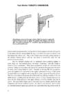


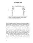


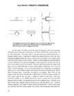


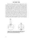
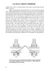


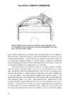


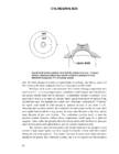


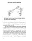


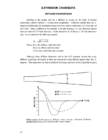

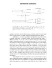


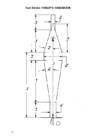


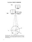
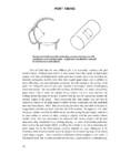


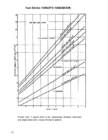


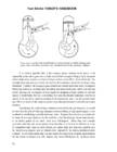


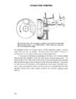


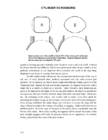


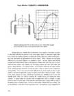


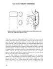

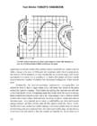
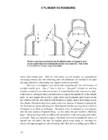


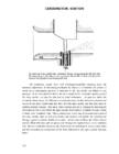
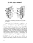
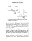


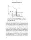


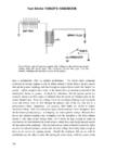


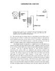


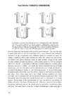


Kõik kommentaarid