Structural Testing Of Homebuilt Aircraft (0)
STRUCTURAL TESTING
OF HOMEBUILTS
Editor's Note: Alex Strojnik's Aviation articles on laminar flow in in all cases of new designs. He
writings and aircraft designs have lightplane design, Alex designed also believes load testing may be in
appeared in Sport Aviation many and built a very low drag powered order in a number of instances
times in the past decade. A native sailplane, the S-2 (Sport Aviation, involving composite airframes.
of Yugoslavia, Alex has very April 1982), which would become While there has been no history of
impressive academic credentials. the first homebuilt motorglider in structural failure in composite
He holds a degree in electrical engi- which International FAI Silver, Gold homebuilts that have been con-
neering, a Ph. D. in aerodynamics .. and Diamond badges would be structed according to the
. and made his way to the the U. S. earned. More recently, he has designer's instructions . . . and
and a faculty position at Arizona designed and built the S-4 Laminar while designers of composite air-
State as a physicist! Though it Magic (Sport Aviation, January craft normally make allowances for
never became his profession, Alex 1990), a tiny 30 h. p. machine that builder variances, still there may be
has continued to carry a torch for held the world's Class C-1.A/O 3 those who have a nagging uneasi-
aviation throughout his life. While kilometer speed record for a time. ness about the integrity of the
still a young engineer and glider Alex is also the author of several structures they have built. To those
instructor in Yugoslavia, he books on the design of aircraft with people, Alex says that load testing
designed and built an all-wood, tail- laminar flow characteristics (see their airframes is so straightfor-
less glider, the S-1 . . . the crash of his classified ad in this issue under ward that there is little reason not
which he fortunately survived. "Books/Films, etc."). to do i t . . . if for no other reason
Channelled into physics by his gov- As a veteran EAA Technical than for peace of mind. In his arti-
ernment, he was not able to get Counselor, Alex often recommends cle, he tells builders of composite
back to personal flying until coming that builders load test their home- aircraft why a load test is desirable,
to the U. S. and ultimately discover- builts before flying them. He how to conduct it and, very impor-
ing EAA and homebuilding. believes this is advisable whenever tantly, how to intrepret the results .
Inspired by Bruce Carmichael's modifications have been made to .. some of which may be both unex-
August and September 1976 Sport an existing design, and, of course, pected and quite surprising.
By ALEX STROJNIK
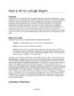
Otructural proof loading, while EAA 61006 in tension - but not until the strain
not supplying all answers to all 2337 E. Manhattan Dr. reaches a huge value of some 0.12 or
questions, will nevertheless tell the Tempe, AZ 85282 12%. This value of the strain is so far
builder a great deal about the out to the right it does not even show
strength and the structural integrity in Figure 1. Similar behavior can be
of his aircraft. It will also contribue straight lines). Twice the stress, twice observed on a tensile specimen of a
to his peace of mind. the strain. The behavior of the certified spruce (yield point around
Let us start by pausing briefly to stretched aluminum alloy (20 24 -T3), 5.3 ksi, ultimate strength about 9.4
consider a peculiar mechanical prop- spruce, or 4130 steel (not shown) is, ksi), or a low carbon steel, or CrMo
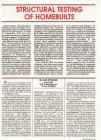
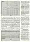
erty of composite materials. Figure 1 however, quite different. Take, for steel, among others.
shows the relationship between the example, aluminum. As the tensile Experiments in the testing device,
tensile stress the material is subjected force is applied, the specimen (for as well as our own daily experience,
to, and the corresponding relative example, in the testing machine) ini- show that as long as the material is
elongation or strain for several materi- tially elongates in proportion with the stressed to less than its "yield point",
als used in aircraft construction. stress. Here the aluminum obeys this it has the ability to return to almost
(Stress is the stretching load per unit "law of proportionality" quite well. its original shape, as soon as the
cross section in pounds/square inch However, at a certain point - let us load disappears. (To be precise, this
or, in short, psi ... with 1,000 psi = 1 call it a "yield point" - on the elasticity of the material does not
ksi; strain is the change in length of a stress/strain line, the original nice lin- have its upper limit at exactly the
part of a specimen of constant cross earity ends. In Figure 1 this occurs at yield point; the difference, however,
section originally 1 inch long, usually an approximate stress of 42 ksi (= at least for materials shown in Figure
expressed in inch/inch or in percent.) 42,000 psi). Any further stress 1, is too small to be considered any
The behavior of the two kinds of car- increase results in a disproportionally further.) This "elastic limit" is a very
bon composite (HM, HT), of Kevlar 49 large increase in strain. Aluminum important point. All structural parts
and of the two glass composites begins to "yield" - an experience of an aircraft (or the kitchen table, or
(S2,E), is nicely "straight", meaning familiar to all homebuilders, by the the chair, or the children's swing, or
that the elongation, or strain, way - with large strain increases for the bridge, or. . .) must be designed
increases in proportion with the stress relatively small stress increases. well under this limit. No structural
all the way up to the breaking point Eventually, somewhere around 64 ksi part may ever, as long as it is used
(circles at the ends of respective (64,000 psi) this specimen will fracture within its design purpose, be stressed
SPORT AVIATION 33
applied and the deformation (and the
elasticity) is no guarantee that it will
250
withstand another 50% increase of
the load, bringing the testing to the
ultimate loads and to that factor of
1.5. What can we do to make cer-
200 tain the wing will not break at the 1.5
HT
load? There is only one way: a com-
posite wing must be tested to 1.5 x
STRESS
its limit load.
leal By the way, for the aircraft meant
150 for Type Certification, FAA requires
that the wing be tested to destruc-
tion. A homebuilder cannot afford
that expense, nevertheless, he
should make sure his structure has
100 all the strength reserve beyond the
limit load. Now, with all the uncer-
APPROXIMATE VALUES ONLY
tainties the composite technologies
VERY HIGH FIBER %
bring with them and with this uncer-
tainty of the gap between the limit
50 load and the ultimate load, it seems
prudent to request that composites
show a considerably higher "safety
factor" than only 1.5. A factor of 2
·O'-'"""""" I--------
between the ultimate load and the
0.01 0.02 0.03 limit load seems a good solution.
STRAIN, i n / i n
Figure 1 Many experienced designers go for
2.2 or even 2.5, knowing how diffi-
cult it is to predict, with calculations
beyond the elasticity limit, because haps up to its breaking point, as the alone, the strength of a composite
we want to use it again and again. material reaches its ultimate strength structure. Just in passing - there is
What would you say about a chair . . . for example, in the main wing another weakness, common to all
' that displays more shrinkage each spar. Engineering recommendation fiberglass structures . . . lack of stiff-
time you rise from it? This elasticity speaks of a safety factor of, say, 1.5, ness. A comparison of two rods, one
also exists in carbon, glass or Kevlar meaning that the aircraft must be aluminum, the other fiberglass (type
composites, as any builder of fiber- built in such a way that in an extreme E, see Figure 1), shows that the fiber-
glass landing gear legs can attest to. case it may bend, experiencing a glass rod stretches almost twice as
However, since there is no pro- strong permanent set, but not quite much under the same tensile stress
nounced yield point, elasticity exists fall apart. In 2024-T3 aluminum, the as aluminum does. Have you ever
approximately all the way up to the ratio between the ultimate tensile watched those fiberglass sailplanes
breaking point. And it is this special strength and the yield strength is as they pull up, just before returning
property of composites that has approximately 1.5 (64,000/42,000 = to land? Their 50 ft. wings often bend
some interesting consequences 1.5). In spruce it is 1.8 in tension up almost 10 feet! Of course, we like
when structurally testing our aircraft. and about 1.4 in compression, mak- this flexibility of fiberglass in our land-
So far we have been looking only ing it somewhere around 1.5 in ing gears, but what about the wing
at tensile forces. Compressive, bending. In composites there is no torsional stiffness at high speed and
shearing, twisting, and bending loads pronounced yield point, no clear the safety against flutter? As a matter
present, in principle, the same pic- elasticity limit. Where is that "safety of record - most modern high effi-
ture that Figure 1 shows, although factor" of, say, 1.5? Suppose we ciency aircraft are sized with regard to
because of additional effects such test load a composite wing to its the stiffness rather than simple
as buckling wing skins and spar limit load and find a good linearity strength. In many light aircraft the dif-
webs, this picture is quite often between the load and the deforma- ference between a stiff and a soft
obscured. When designing an air- tion all the way up to this limit load. wing is only a few additional pounds.
craft, we make sure that no structural Fine, but - and this is the crucial We are now ready to begin the
part will ever be stressed beyond its point - how do we know that this structural testing. It must be under-
yield point - which means that it will composite wing still possesses that stood that the complete testing of an
always operate within elasticity lim- safety factor of 1.5 beyond the tested aircraft to be Type Certified repre-
its. Yet, what happens if somehow point? With an aluminum or wooden sents almost as much work as
the pilot overloads his aircraft, either wing we would know because as building it. The joke goes that the
by overdoing a pull-up or too steep a long as our tests indicate the entire paperwork for an aircraft to be
turn or by entering an extreme gust . required linearity between the load Certified by the FAA weighs as much
. . or by combination of both (as hap- and the wing deformation, the struc- as the prototype itself. Are you sure
pened during the 1989 Reno races ture has not yet reached the limit it's a joke? The amateur builder who
with a tragic result)? point and the elasticity limit. With a is expected to follow established
Obviously, there must be some composite wing this linearity says practices as outlined in many EAA
safety built into the aircraft so it does nothing about what happens if we "How To" books will most likely test
not fall apart immediately upon only slightly increase the load. his wing for bending of the main spar
exceeding the allowed "limit" loads. Maybe the next pound will break the and for the torsional strength and
Well, there is a certain degree of wing? How close to the breaking stiffness of the wing skin, the horizon-
safety built into an aluminum or wood point is a wing? The mere fact that tal tail and the vertical tail for the
structure . . . inherent in its ability to the composite wing shows an excel- bending and, in connection with the
deform beyond the yield point, per- lent linearity between the loads two previous tests, the bending and
34 MARCH 1992
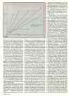
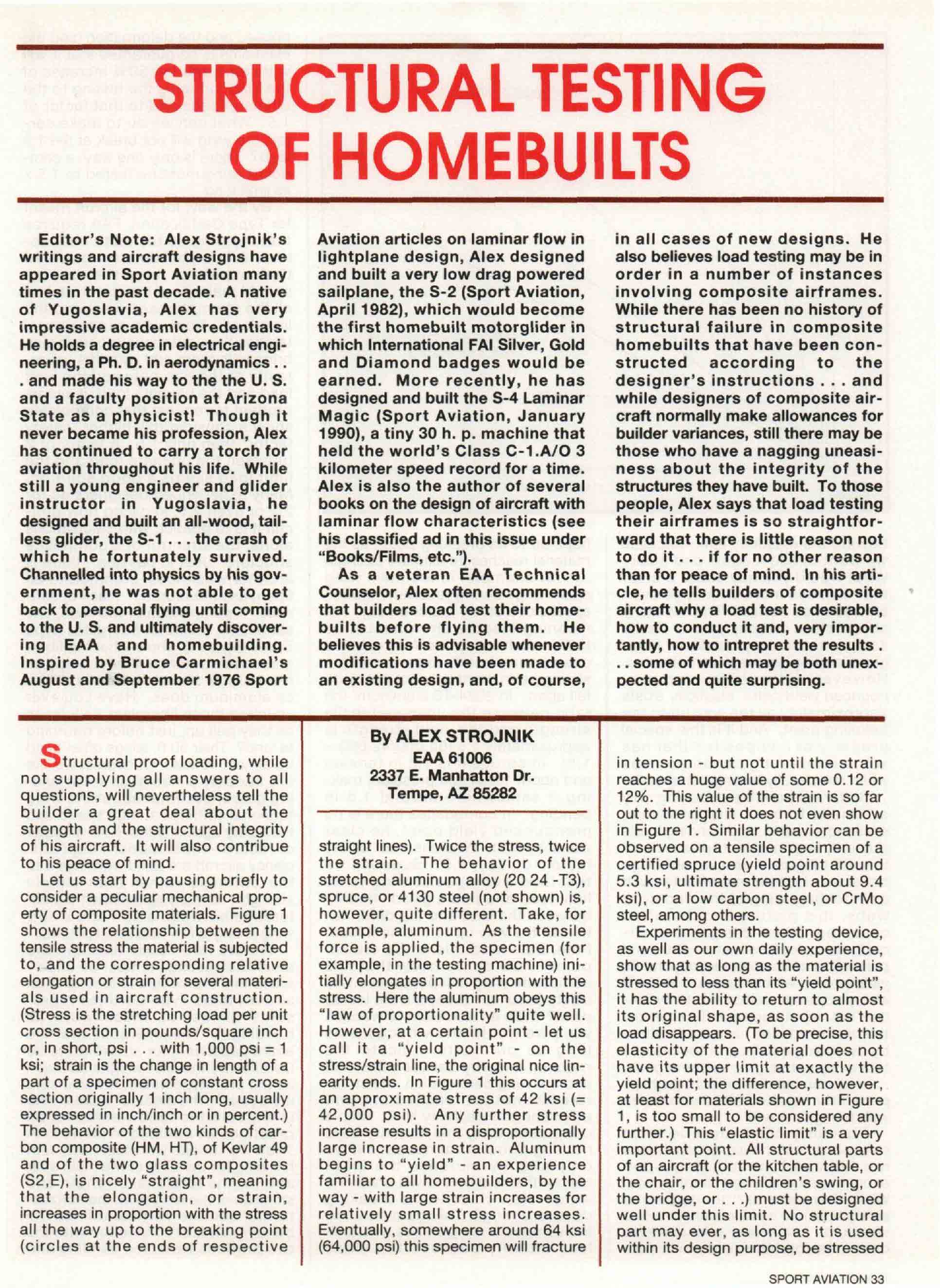
Figure 2L Figure 2R
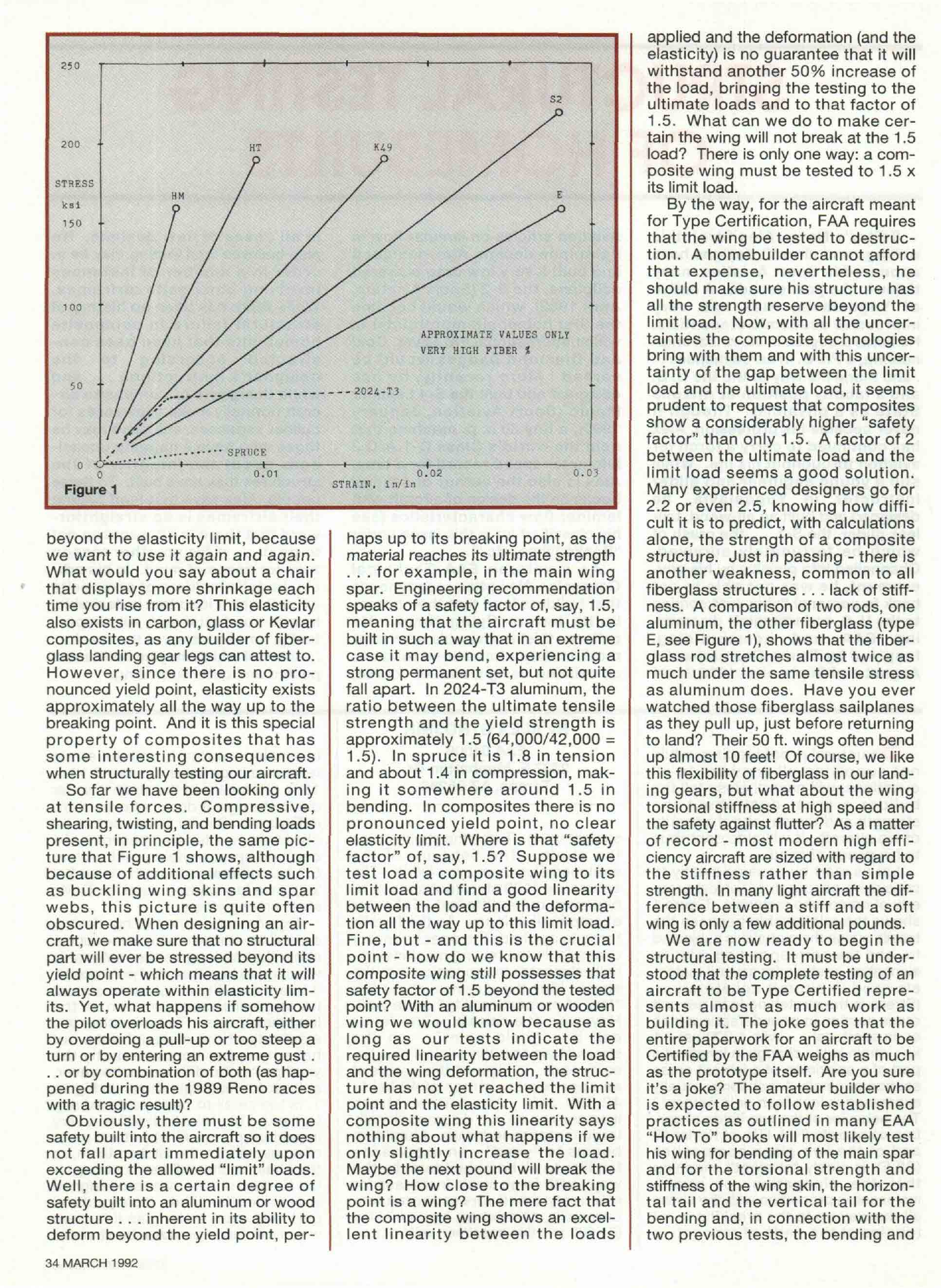
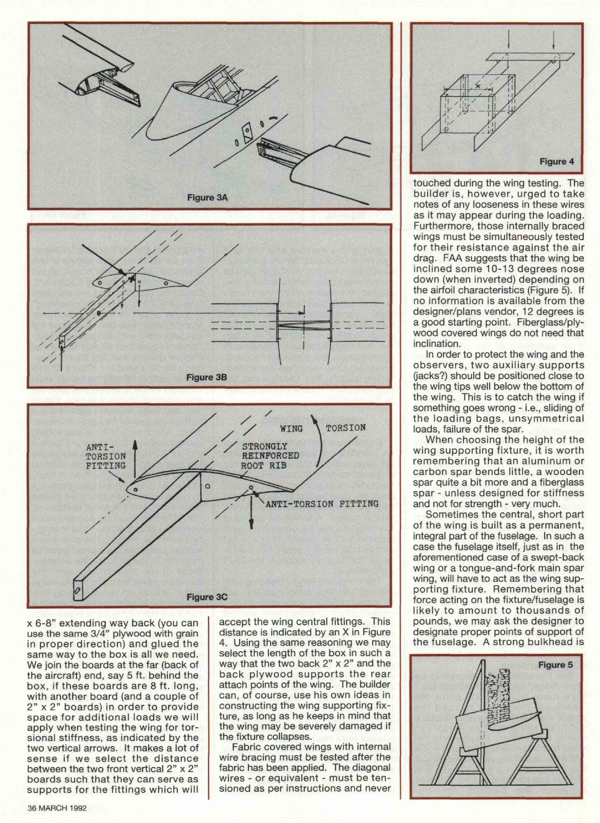
torsional strength of the fuselage. signer/plans vendor and the EAA Additional Safety Factors for them.
The designer or the plans vendor usu- Technical Counselor before the struc- Even so, fractures often appear in this
ally indicates either in the technical tural testing begins. It should also be area (did the designer forget about
description or right in the plans to mentioned that, while most often these Additional Safety Factors?).
what "load factor" he designed his quoted, the maneuvering load factor During the proof loading, we will care-
aircraft. Unless explained otherwise, is not the only load factor important in fully LISTEN to possible "crackling"
the load factor refers to the "limit" flight. Just as important, especially in sounds close to these junctions.
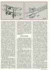
load, as expected during the normal sailplanes, which must seek vertical Many modern two-part wings use the
operation of the aircraft when pulling gusts, is the so-called gust load fac- so-called fork-and-tongue spar junc-
it up suddenly at the prescribed tor. In a majority of light amateur built tions. Figure 3(a) shows the metal
maneuvering speed. The FAA has sport planes, the gust load factor is, (French Cricket) and 3(b) the compos-
categorized load factors as follows: however, often less than the maneu- ite (wood?) solution. Wings of this
3.8 (normal category), 4.4 (utility), 5.3 vering load factor. In any case, the kind should preferably be tested while
(sailplanes and motorgliders), and 6 designer/plans vendor can easily clar- installed in the fuselage because the
for aerobatic aircraft. The designer of ify the situation. anti-torsional fittings and pins, Figure
a homebuilt usually goes higher than 3(c), and holes require a tight fit and a
the FAA load factors, realizing the TESTING THE WING certain degree of freedom in move-
homebuilder may not have the quali- ment, which only the fuselage itself
ties of a supervised aircraft factory Experience shows that the part of can guarantee. The arrow in Figure 3
worker. It must also be understood an experimental aircraft most likely to and an X indicate the area where the
that these (minimum!) load factors fail structurally is the wing. While an top spar flange (cap) is often crushed
apply to the entire aircraft, not just the engineering type homebuilder might due to insufficient attention to local
wing. During that sudden pull-up, the consider an extensive, detailed and stresses. Experienced designers like
wing generates a lift that is by a "load complex wing testing project, a great to over-dimension this area of the
factor" larger than the weight of the deal can be accomplished with very main spar (and the local reinforced
aircraft. The result is that the reaction simple means. A structural testing of rib). Others become experienced
to this suddenly increased lifting force the wing as will be described here designers after building - and testing -
presses the pilot onto his seat with requires so little money, time and hot two or three wings. The one-piece
the amount equal to that "load factor" coffee that we will really have diffi- wing experiences the highest bending
times his weight. A pilot weighing 200 culty finding an excuse for NOT moment at the point of the engage-
Ibs. pulling up at n = 4.4 will press performing it. ment of its main fitting with the
onto the seat at a "weight" of 880 Ibs. The complete wing - meaning with corresponding fitting in the fuselage
The 30 pound battery will "weigh" 132 ailerons and flaps firmly installed - will walls. It is worth remembering that
lbs., the 180 pound engine will react be tested inverted. If the wing is com- this highest bending moment remains
as if it suddenly weighs 792 Ibs. Has posed of two or more parts, we first constant throughout the cross-sec-
the designer constructed the pilot's inspect the spar junctions. In a can- tion of the fuselage. Swept-back
seat for continuously and repeatedly tilever wing we pay special attention wings should also be tested while
sustaining, elastically, an 880 lb. pilot? to metal fittings joining the spar-spar firmly installed in the fuselage, as it
Look around and you will find some or spar-fuselage and we concentrate may be difficult to construct a simple,
surprising answers. on the bolts and main pins. Later, yet reliable fixture for such wings. In
Will the seat of the aircraft to be when the wing loading is over, we will any case, the wing supporting fixture
proof tested elastically hold 880 lbs.? again inspect these parts to find out if should provide a sturdy support not
How many builders will allow the there have been some changes in just for the spar bending test but also
Technical Counselor to load the their appearance (hole elongations? for the following torsional test.
seat(s) with 880 Ibs. (each!)? Maybe a bolt/nut looseness?). Figure 2L shows Figure 4 shows, schematically,
call to the designer/plans vendor can a typical wooden spar central fitting how a fixture for a light aircraft could
clarify the matter. Maybe only the (please note the bolts are NOT situ- look. A square box made of house-
wing has been designed for n = 4.4 ated along one single line), and Figure building quality plywood, some 3/4"
while the rest of the aircraft remains at 2R a metal spar (Monerai). During the thick, fastened together at the corners
the mercy of n = 2 or 3. These and wing bending, these fittings and bolts by 2" x 2" boards, using Elmer's car-
similar questions must be clarified will be subject to particularly high penter's glue and some nails to speed
between the builder, the de- stresses - this is why FAA prescribes it up, and a couple of boards, say 3/4"
SPORT AVIATION 35
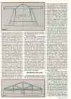
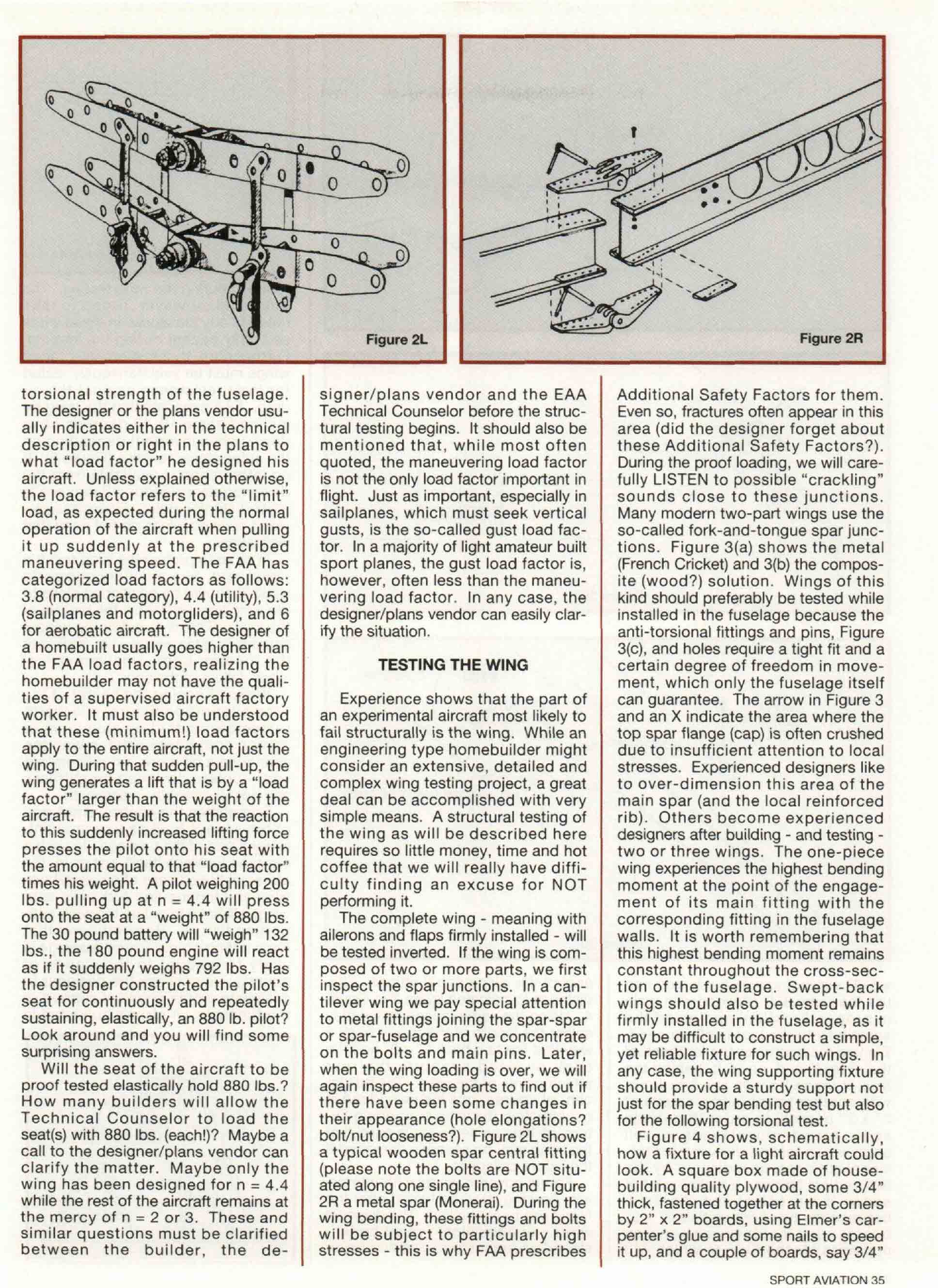
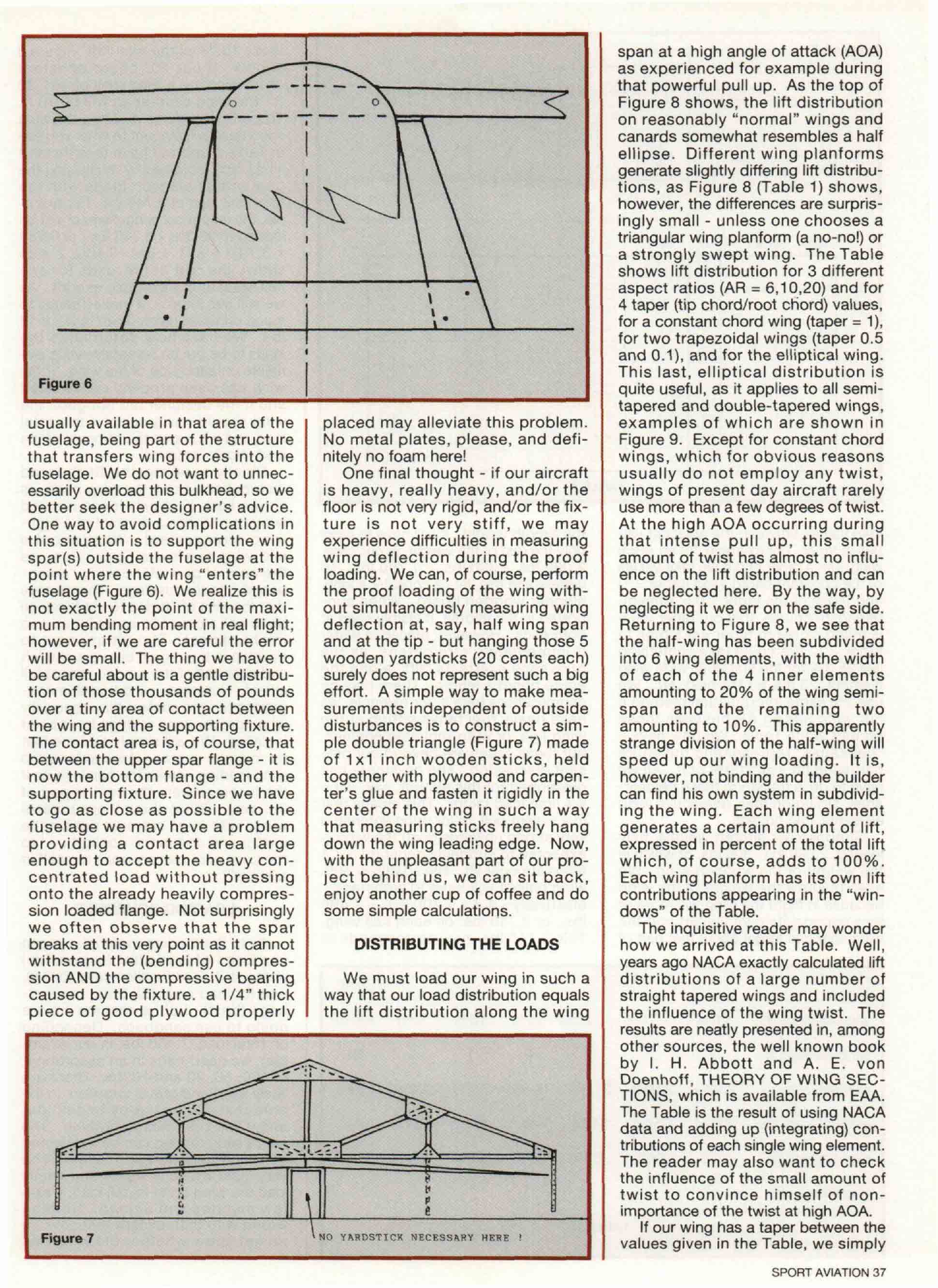
Figure 4
touched during the wing testing. The
Figure 3A builder is, however, urged to take
notes of any looseness in these wires
as it may appear during the loading.
Furthermore, those internally braced
wings must be simultaneously tested
for their resistance against the air
drag. FAA suggests that the wing be
inclined some 10-13 degrees nose
down (when inverted) depending on
the airfoil characteristics (Figure 5). If
no information is available from the
designer/plans vendor, 12 degrees is
a good starting point. Fiberglass/ply-
wood covered wings do not need that
inclination.
In order to protect the wing and the
observers, two auxiliary supports
Figure 3B (jacks?) should be positioned close to
the wing tips well below the bottom of
the wing. This is to catch the wing if
something goes wrong - i.e., sliding of
the loading bags, unsymmetrical
TORSION loads, failure of the spar.
When choosing the height of the
ANTI- wing supporting fixture, it is worth
TORSION REINFORCED
FITTING ROOT RIB remembering that an aluminum or
carbon spar bends little, a wooden
spar quite a bit more and a fiberglass
spar - unless designed for stiffness
ANTI-TORSION FITTING and not for strength - very much.
Sometimes the central, short part
of the wing is built as a permanent,
integral part of the fuselage. In such a
case the fuselage itself, just as in the
aforementioned case of a swept-back
wing or a tongue-and-fork main spar
wing, will have to act as the wing sup-
porting fixture. Remembering that
Figure 3C force acting on the fixture/fuselage is
likely to amount to thousands of
x 6-8" extending way back (you can accept the wing central fittings. This pounds, we may ask the designer to
use the same 3/4" plywood with grain distance is indicated by an X in Figure designate proper points of support of
in proper direction) and glued the 4. Using the same reasoning we may the fuselage. A strong bulkhead is
same way to the box is all we need. select the length of the box in such a
We join the boards at the far (back of way that the two back 2" x 2" and the Figure 5
the aircraft) end, say 5 ft. behind the back plywood supports the rear
box, if these boards are 8 ft. long, attach points of the wing. The builder
with another board (and a couple of can, of course, use his own ideas in
2" x 2" boards) in order to provide constructing the wing supporting fix-
space for additional loads we will ture, as long as he keeps in mind that
apply when testing the wing for tor- the wing may be severely damaged if
sional stiffness, as indicated by the the fixture collapses.
two vertical arrows. It makes a lot of Fabric covered wings with internal
sense if we select the distance wire bracing must be tested after the
between the two front vertical 2" x 2" fabric has been applied. The diagonal
boards such that they can serve as wires - or equivalent - must be ten-
supports for the fittings which will sioned as per instructions and never
36 MARCH 1992
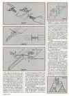
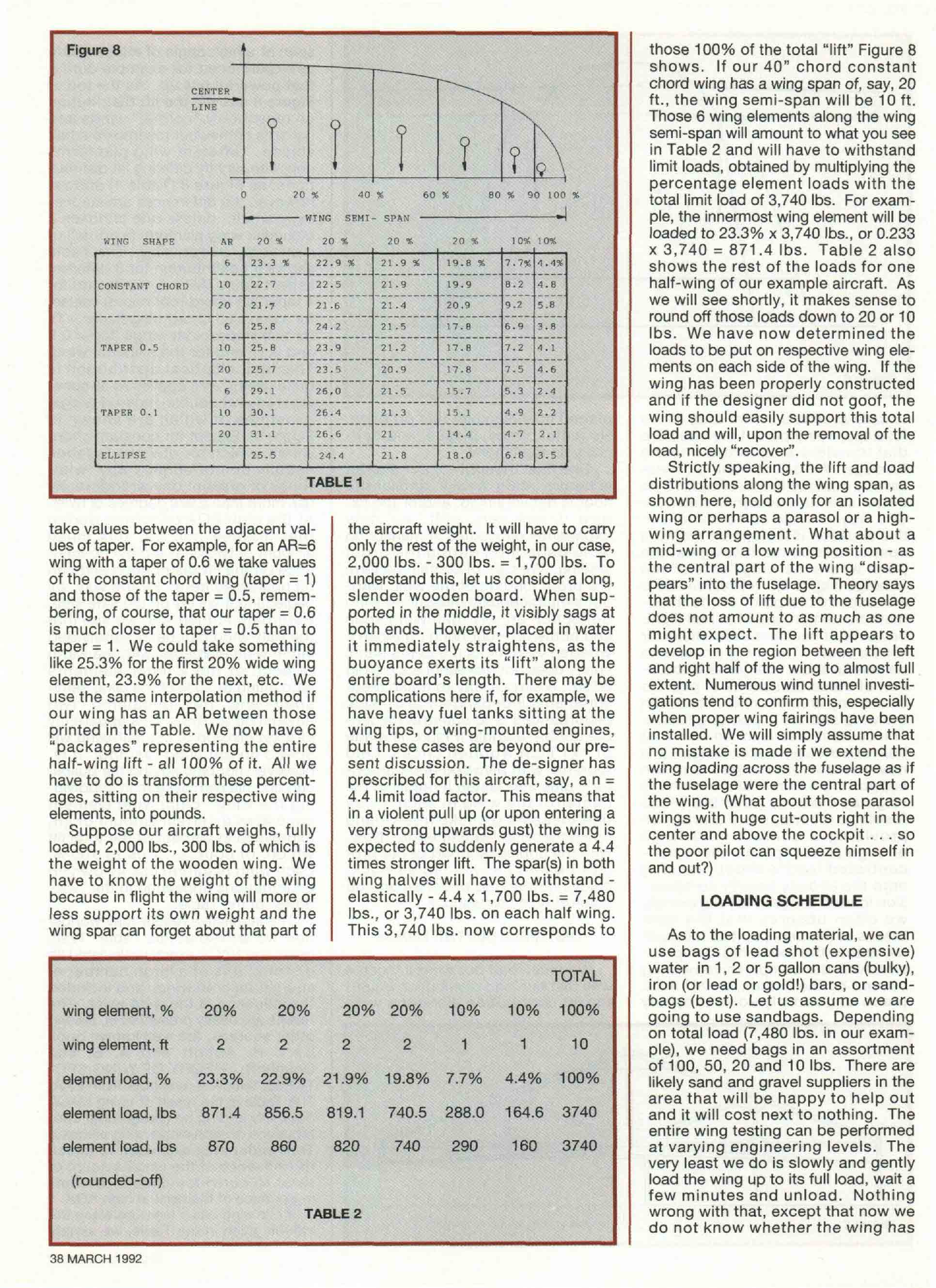
span at a high angle of attack (AOA)
as experienced for example during
that powerful pull up. As the top of
Figure 8 shows, the lift distribution
on reasonably "normal" wings and
canards somewhat resembles a half
ellipse. Different wing planforms
generate slightly differing lift distribu-
tions, as Figure 8 (Table 1) shows,
however, the differences are surpris-
ingly small - unless one chooses a
triangular wing planform (a no-no!) or
a strongly swept wing. The Table
shows lift distribution for 3 different
aspect ratios (AR = 6,10,20) and for
4 taper (tip chord/root chord) values,
for a constant chord wing (taper = 1),
for two trapezoidal wings (taper 0.5
and 0.1), and for the elliptical wing.
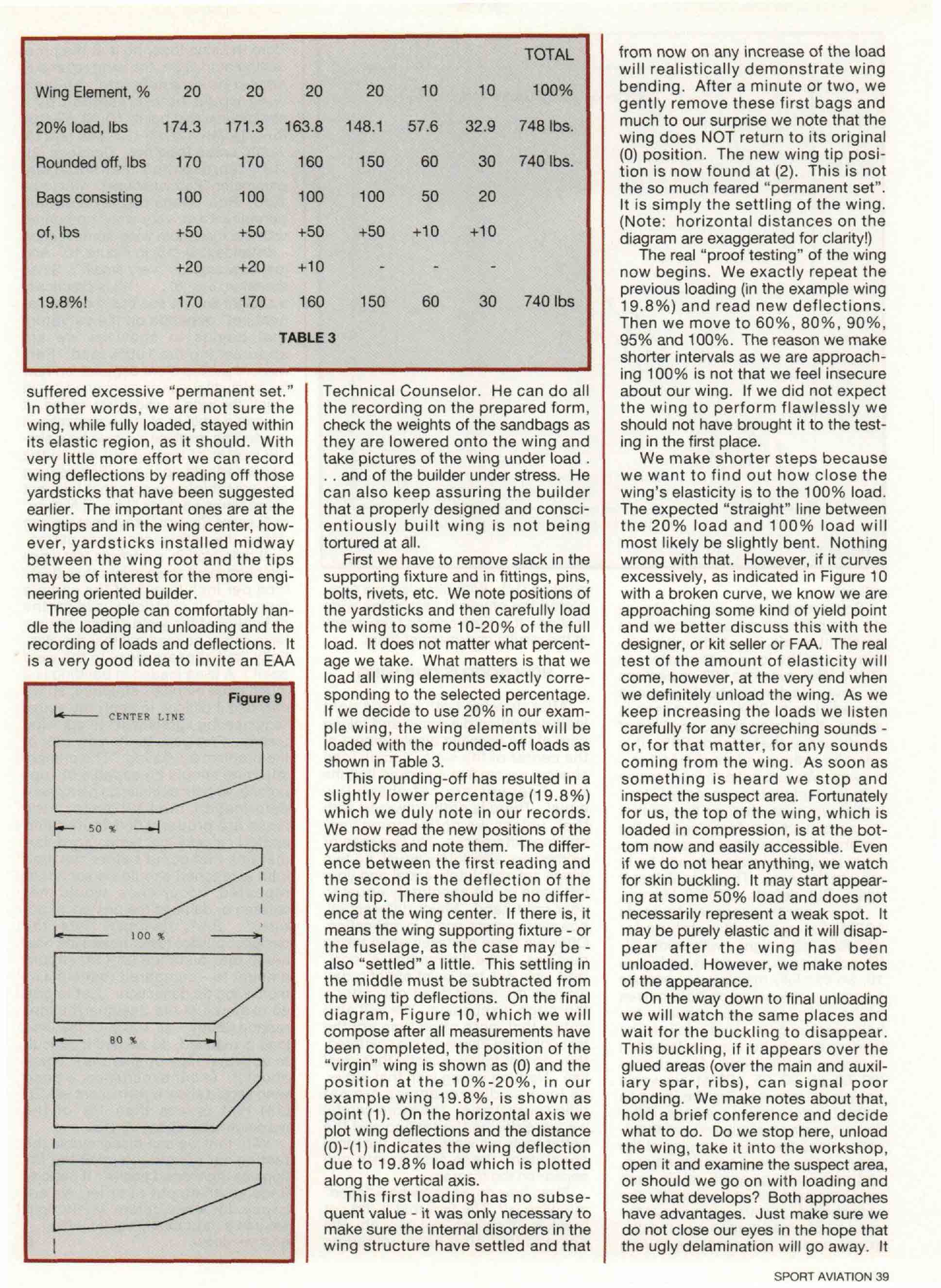
This last, elliptical distribution is
Figure 6 quite useful, as it applies to all semi-
tapered and double-tapered wings,
usually available in that area of the placed may alleviate this problem. examples of which are shown in
fuselage, being part of the structure No metal plates, please, and defi- Figure 9. Except for constant chord
that transfers wing forces into the nitely no foam here! wings, which for obvious reasons
fuselage. We do not want to unnec- One final thought - if our aircraft usually do not employ any twist,
essarily overload this bulkhead, so we is heavy, really heavy, and/or the wings of present day aircraft rarely
better seek the designer's advice. floor is not very rigid, and/or the fix- use more than a few degrees of twist.
One way to avoid complications in ture is not very stiff, we may At the high AOA occurring during
this situation is to support the wing experience difficulties in measuring that intense pull up, this small
spar(s) outside the fuselage at the wing deflection during the proof amount of twist has almost no influ-
point where the wing "enters" the loading. We can, of course, perform ence on the lift distribution and can
fuselage (Figure 6). We realize this is the proof loading of the wing with- be neglected here. By the way, by
not exactly the point of the maxi- out simultaneously measuring wing neglecting it we err on the safe side.
mum bending moment in real flight; deflection at, say, half wing span Returning to Figure 8, we see that
however, if we are careful the error and at the tip - but hanging those 5 the half-wing has been subdivided
will be small. The thing we have to wooden yardsticks (20 cents each) into 6 wing elements, with the width
be careful about is a gentle distribu- surely does not represent such a big of each of the 4 inner elements
tion of those thousands of pounds effort. A simple way to make mea- amounting to 20% of the wing semi-
over a tiny area of contact between surements independent of outside span and the remaining two
the wing and the supporting fixture. disturbances is to construct a sim- amounting to 10%. This apparently
The contact area is, of course, that ple double triangle (Figure 7) made strange division of the half-wing will
between the upper spar flange - it is of 1x1 inch wooden sticks, held speed up our wing loading. It is,
now the bottom flange - and the together with plywood and carpen- however, not binding and the builder
supporting fixture. Since we have ter's glue and fasten it rigidly in the can find his own system in subdivid-
to go as close as possible to the center of the wing in such a way ing the wing. Each wing element
fuselage we may have a problem that measuring sticks freely hang generates a certain amount of lift,
providing a contact area large down the wing leading edge. Now, expressed in percent of the total lift
enough to accept the heavy con- with the unpleasant part of our pro- which, of course, adds to 100%.
centrated load without pressing ject behind us, we can sit back, Each wing planform has its own lift
onto the already heavily compres- enjoy another cup of coffee and do contributions appearing in the "win-
sion loaded flange. Not surprisingly some simple calculations. dows" of the Table.
we often observe that the spar The inquisitive reader may wonder
breaks at this very point as it cannot DISTRIBUTING THE LOADS how we arrived at this Table. Well,
withstand the (bending) compres- years ago NACA exactly calculated lift
sion AND the compressive bearing We must load our wing in such a distributions of a large number of
caused by the fixture, a 1/4" thick way that our load distribution equals straight tapered wings and included
piece of good plywood properly the lift distribution along the wing the influence of the wing twist. The
results are neatly presented in, among
other sources, the well known book
by I. H. Abbott and A. E. von
Doenhoff, THEORY OF WING SEC-
TIONS, which is available from EAA.
The Table is the result of using NACA
data and adding up (integrating) con-
tributions of each single wing element.
The reader may also want to check
the influence of the small amount of
twist to convince himself of non-
importance of the twist at high AOA.
If our wing has a taper between the
values given in the Table, we simply
SPORT AVIATION 37
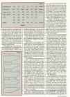
Figure 8 those 100% of the total "lift" Figure 8
shows. If our 40" chord constant
CENTER
chord wing has a wing span of, say, 20
LINE ft., the wing semi-span will be 10 ft.
Those 6 wing elements along the wing
semi-span will amount to what you see
I I 1 ? ? 9\
in Table 2 and will have to withstand
limit loads, obtained by multiplying the
percentage element loads with the
0 20 % 40 % 60 % 80 % 90 100 %
total limit load of 3,740 Ibs. For exam-
|«»------------ WING SEMI ple, the innermost wing element will be
WING SHAPE AR ?0 % 20 % 20 % 20 % 10* 10%
loaded to 23.3% x 3,740 lbs., or 0.233
x 3,740 = 871.4 Ibs. Table 2 also
6 23.3 % 22.9 % 21 .9 % 19.8 % 7.7% 4.4%
shows the rest of the loads for one
CONSTANT CHORD 10 22.7 22.5 21 .9 19.9 8.2 4.8 half-wing of our example aircraft. As
?0 21.7 21.6 21 .4 20.9 9.2 5.8 we will see shortly, it makes sense to
6 25.8 24.2 21 .5 17.8 6.9 3.8
round off those loads down to 20 or 10
Ibs. We have now determined the
TAPER 0.5 10 25.8 23.9 21.2 17.8 7.2 4.1 loads to be put on respective wing ele-
20 25.7 23.5 20.9 17.8 7.5 4.6 ments on each side of the wing. If the
6 29.1 26,0 21.5 15.7 5.3 2.4
wing has been properly constructed
and if the designer did not goof, the
TAPER 0.1 10 30.1 26.4 21.3 15.1 4.9 2.2
wing should easily support this total
20 31.1 26.6 21 14.4 4.7 2.1 load and will, upon the removal of the
ELLIPSE 25.5 24.4 21 .8 18.0 6.8 3.5 load, nicely "recover".
Strictly speaking, the lift and load
TABLE 1 distributions along the wing span, as
shown here, hold only for an isolated
wing or perhaps a parasol or a high-
take values between the adjacent val- the aircraft weight. It will have to carry wing arrangement. What about a
ues of taper. For example, for an AR=6 only the rest of the weight, in our case, mid-wing or a low wing position - as
wing with a taper of 0.6 we take values 2,000 Ibs. - 300 Ibs. = 1,700 Ibs. To the central part of the wing "disap-
of the constant chord wing (taper = 1) understand this, let us consider a long, pears" into the fuselage. Theory says
and those of the taper = 0.5, remem- slender wooden board. When sup- that the loss of lift due to the fuselage
bering, of course, that our taper = 0.6 ported in the middle, it visibly sags at does not amount to as much as one
is much closer to taper = 0.5 than to both ends. However, placed in water might expect. The lift appears to
taper = 1. We could take something it immediately straightens, as the develop in the region between the left
like 25.3% for the first 20% wide wing buoyance exerts its "lift" along the and right half of the wing to almost full
element, 23.9% for the next, etc. We entire board's length. There may be extent. Numerous wind tunnel investi-
use the same interpolation method if complications here if, for example, we gations tend to confirm this, especially
our wing has an AR between those have heavy fuel tanks sitting at the when proper wing fairings have been
printed in the Table. We now have 6 wing tips, or wing-mounted engines, installed. We will simply assume that
"packages" representing the entire but these cases are beyond our pre- no mistake is made if we extend the
half-wing lift - all 100% of it. All we sent discussion. The de-signer has wing loading across the fuselage as if
have to do is transform these percent- prescribed for this aircraft, say, a n = the fuselage were the central part of
ages, sitting on their respective wing 4.4 limit load factor. This means that the wing. (What about those parasol
elements, into pounds. in a violent pull up (or upon entering a wings with huge cut-outs right in the
Suppose our aircraft weighs, fully very strong upwards gust) the wing is center and above the c o c k p i t . . . so
loaded, 2,000 lbs., 300 Ibs. of which is expected to suddenly generate a 4.4 the poor pilot can squeeze himself in
the weight of the wooden wing. We times stronger lift. The spar(s) in both and out?)
have to know the weight of the wing wing halves will have to withstand -
because in flight the wing will more or elastically - 4.4 x 1,700 Ibs. = 7,480 LOADING SCHEDULE
less support its own weight and the lbs., or 3,740 Ibs. on each half wing.
wing spar can forget about that part of This 3,740 Ibs. now corresponds to As to the loading material, we can
use bags of lead shot (expensive)
water in 1, 2 or 5 gallon cans (bulky),
TOTAL
iron (or lead or gold!) bars, or sand-
bags (best). Let us assume we are
wing element, % 20% 20% 20% 20% 10% 10% 100% going to use sandbags. Depending
on total load (7,480 Ibs. in our exam-
wing element, ft 2 2 2 2 1 1 10 ple), we need bags in an assortment
of 100, 50, 20 and 10 Ibs. There are
element load, % 23.3% 22.9% 21.9% 19.8% 7.7% 4.4% 100% likely sand and gravel suppliers in the
area that will be happy to help out
element load, Ibs 871.4 856.5 819.1 740.5 288.0 164.6 3740 and it will cost next to nothing. The
entire wing testing can be performed
element load, Ibs 870 860 820 740 290 160 3740 at varying engineering levels. The
very least we do is slowly and gently
(rounded-off) load the wing up to its full load, wait a
few minutes and unload. Nothing
TABLE 2 wrong with that, except that now we
do not know whether the wing has
38 MARCH 1992
TOTAL from now on any increase of the load
will realistically demonstrate wing
Wing Element, % 20 20 20 20 10 10 100% bending. After a minute or two, we
gently remove these first bags and
20% load, Ibs 174.3 171.3 163.8 148.1 57.6 32.9 748 Ibs. much to our surprise we note that the
wing does NOT return to its original
150 60 30 740 Ibs. (0) position. The new wing tip posi-
Rounded off, Ibs 170 170 160
tion is now found at (2). This is not
the so much feared "permanent set".
Bags consisting 100 100 100 100 50 20
It is simply the settling of the wing.
(Note: horizontal distances on the
of, Ibs +50 +50 +50 +50 +10 +10 diagram are exaggerated for clarity!)
The real "proof testing" of the wing
+20 +20 +10 - - - now begins. We exactly repeat the
previous loading (in the example wing
19.8%! 170 170 160 150 60 30 740 Ibs 19.8%) and read new deflections.
Then we move to 60%, 80%, 90%,
TABLE 3 95% and 100%. The reason we make
shorter intervals as we are approach-
ing 100% is not that we feel insecure
suffered excessive "permanent set." Technical Counselor. He can do all about our wing. If we did not expect
In other words, we are not sure the the recording on the prepared form, the wing to perform flawlessly we
wing, while fully loaded, stayed within check the weights of the sandbags as should not have brought it to the test-
its elastic region, as it should. With they are lowered onto the wing and ing in the first place.
very little more effort we can record take pictures of the wing under load . We make shorter steps because
wing deflections by reading off those . . and of the builder under stress. He we want to find out how close the
yardsticks that have been suggested can also keep assuring the builder wing's elasticity is to the 100% load.
earlier. The important ones are at the that a properly designed and consci- The expected "straight" line between
wingtips and in the wing center, how- entiously built wing is not being the 20% load and 100% load will
ever, yardsticks installed midway tortured at all. most likely be slightly bent. Nothing
between the wing root and the tips First we have to remove slack in the wrong with that. However, if it curves
may be of interest for the more engi- supporting fixture and in fittings, pins, excessively, as indicated in Figure 10
neering oriented builder. bolts, rivets, etc. We note positions of with a broken curve, we know we are
Three people can comfortably han- the yardsticks and then carefully load approaching some kind of yield point
dle the loading and unloading and the the wing to some 10-20% of the full and we better discuss this with the
recording of loads and deflections. It load. It does not matter what percent- designer, or kit seller or FAA. The real
is a very good idea to invite an EAA age we take. What matters is that we test of the amount of elasticity will
load all wing elements exactly corre- come, however, at the very end when
Figure 9 sponding to the selected percentage. we definitely unload the wing. As we
CENTER LINE If we decide to use 20% in our exam- keep increasing the loads we listen
ple wing, the wing elements will be carefully for any screeching sounds -
loaded with the rounded-off loads as or, for that matter, for any sounds
shown in Table 3. coming from the wing. As soon as
This rounding-off has resulted in a something is heard we stop and
slightly lower percentage (19.8%) inspect the suspect area. Fortunately
which we duly note in our records. for us, the top of the wing, which is
We now read the new positions of the loaded in compression, is at the bot-
yardsticks and note them. The differ- tom now and easily accessible. Even
ence between the first reading and if we do not hear anything, we watch
the second is the deflection of the for skin buckling. It may start appear-
wing tip. There should be no differ- ing at some 50% load and does not
ence at the wing center. If there is, it necessarily represent a weak spot. It
100 * means the wing supporting fixture - or may be purely elastic and it will disap-
the fuselage, as the case may be - pear after the wing has been
also "settled" a little. This settling in unloaded. However, we make notes
the middle must be subtracted from of the appearance.
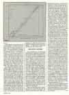
the wing tip deflections. On the final On the way down to final unloading
diagram, Figure 10, which we will we will watch the same places and
80 %
compose after all measurements have wait for the buckling to disappear.
been completed, the position of the This buckling, if it appears over the
"virgin" wing is shown as (0) and the glued areas (over the main and auxil-
position at the 10%-20%, in our iary spar, ribs), can signal poor
example wing 19.8%, is shown as bonding. We make notes about that,
point (1). On the horizontal axis we hold a brief conference and decide
plot wing deflections and the distance what to do. Do we stop here, unload
(0)-(1) indicates the wing deflection the wing, take it into the workshop,
due to 19.8% load which is plotted open it and examine the suspect area,
along the vertical axis. or should we go on with loading and
This first loading has no subse- see what develops? Both approaches
quent value - it was only necessary to have advantages. Just make sure we
make sure the internal disorders in the do not close our eyes in the hope that
wing structure have settled and that the ugly delamination will go away. It
SPORT AVIATION 39
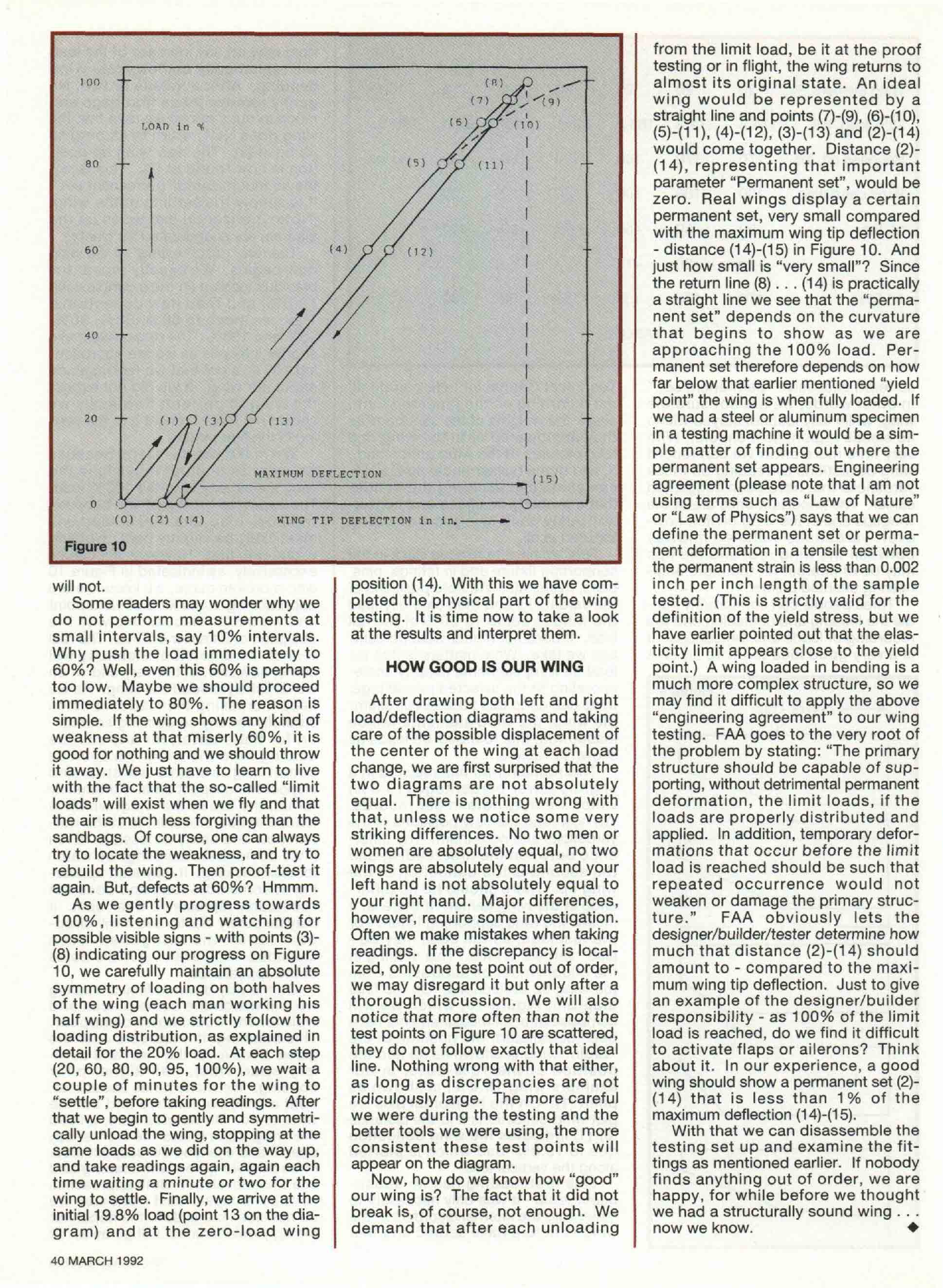
from the limit load, be it at the proof
testing or in flight, the wing returns to
almost its original state. An ideal
wing would be represented by a
straight line and points (7)-(9), (6)-(10),
(5)-(11),(4H12),(3)-(13)and(2H14)
would come together. Distance (2)-
(14), representing that important
parameter "Permanent set", would be
zero. Real wings display a certain
permanent set, very small compared
with the maximum wing tip deflection
- distance (14)-(15) in Figure 10. And
just how small is "very small"? Since
the return line ( 8 ) . . . (14) is practically
a straight line we see that the "perma-
nent set" depends on the curvature
that begins to show as we are
approaching the 100% load. Per-
manent set therefore depends on how
far below that earlier mentioned "yield
point" the wing is when fully loaded. If
20 - - we had a steel or aluminum specimen
in a testing machine it would be a sim-
ple matter of finding out where the
permanent set appears. Engineering
agreement (please note that I am not
using terms such as "Law of Nature"
(0) (2') ( 1 4 ) WING TIP DEFLECTION in in.- or "Law of Physics") says that we can
define the permanent set or perma-
Figure 10 nent deformation in a tensile test when
the permanent strain is less than 0.002
will not. position (14). With this we have com- inch per inch length of the sample
Some readers may wonder why we pleted the physical part of the wing tested. (This is strictly valid for the
do not perform measurements at testing. It is time now to take a look definition of the yield stress, but we
small intervals, say 10% intervals. at the results and interpret them. have earlier pointed out that the elas-
Why push the load immediately to ticity limit appears close to the yield
60%? Well, even this 60% is perhaps HOW GOOD IS OUR WING point.) A wing loaded in bending is a
too low. Maybe we should proceed much more complex structure, so we
immediately to 80%. The reason is After drawing both left and right may find it difficult to apply the above
simple. If the wing shows any kind of load/deflection diagrams and taking "engineering agreement" to our wing
weakness at that miserly 60%, it is care of the possible displacement of testing. FAA goes to the very root of
good for nothing and we should throw the center of the wing at each load the problem by stating: "The primary
it away. We just have to learn to live change, we are first surprised that the structure should be capable of sup-
with the fact that the so-called "limit two diagrams are not absolutely porting, without detrimental permanent
loads" will exist when we fly and that equal. There is nothing wrong with deformation, the limit loads, if the
the air is much less forgiving than the that, unless we notice some very loads are properly distributed and
sandbags. Of course, one can always striking differences. No two men or applied. In addition, temporary defor-
try to locate the weakness, and try to women are absolutely equal, no two mations that occur before the limit
rebuild the wing. Then proof-test it wings are absolutely equal and your load is reached should be such that
again. But, defects at 60%? Hmmm. left hand is not absolutely equal to repeated occurrence would not
As we gently progress towards your right hand. Major differences, weaken or damage the primary struc-
100%, listening and watching for however, require some investigation. ture." FAA obviously lets the
possible visible signs - with points (3)- Often we make mistakes when taking designer/builder/tester determine how
(8) indicating our progress on Figure readings. If the discrepancy is local- much that distance (2)-(14) should
10, we carefully maintain an absolute ized, only one test point out of order, amount to - compared to the maxi-
symmetry of loading on both halves we may disregard it but only after a mum wing tip deflection. Just to give
of the wing (each man working his thorough discussion. We will also an example of the designer/builder
half wing) and we strictly follow the notice that more often than not the responsibility - as 100% of the limit
loading distribution, as explained in test points on Figure 10 are scattered, load is reached, do we find it difficult
detail for the 20% load. At each step they do not follow exactly that ideal to activate flaps or ailerons? Think
(20, 60, 80, 90, 95, 100%), we wait a line. Nothing wrong with that either, about it. In our experience, a good
couple of minutes for the wing to as long as discrepancies are not wing should show a permanent set (2)-
"settle", before taking readings. After ridiculously large. The more careful (14) that is less than 1% of the
that we begin to gently and symmetri- we were during the testing and the maximum deflection (14)-(15).
cally unload the wing, stopping at the better tools we were using, the more With that we can disassemble the
same loads as we did on the way up, consistent these test points will testing set up and examine the fit-
and take readings again, again each appear on the diagram. tings as mentioned earlier. If nobody
time waiting a minute or two for the Now, how do we know how "good" finds anything out of order, we are
wing to settle. Finally, we arrive at the our wing is? The fact that it did not happy, for while before we thought
initial 19.8% load (point 13 on the dia- break is, of course, not enough. We we had a structurally sound wing . . .
gram) and at the zero-load wing demand that after each unloading now we know. *
40 MARCH 1992
Kodusel meetodil valmistatud lennumasina vastupidavuskatsed.
Sarnased õppematerjalid
![Fitness In Soccer]()
409
pdf
Fitness In Soccer
8 Speed ......................................................................................................... 115
7.9 Tips ................................................................................................................... 117
7.10 Exercises .................................................................................................... 118
8. FITNESS TESTING .................................................................................................... 123
8.1 Introduction ................................................................................................. 123
8.2 Criteria ........................................................................................................ 124
8.3 Why measure? .......................
![Book Analog Interfacing to Embedded Microprocessors]()
568
pdf
Book Analog Interfacing to Embedded Microprocessors
PC/104 CPU board, the relaxed timing constraints of PC/104 may make
layout easier. Many low-volume products simply do not sell enough units to
justify the higher development costs associated with PC/104 Plus. Of course,
this assumes that the PC/104 bus will support the necessary data rates. Similar
considerations apply to other buses, such as PCI and Compact PCI.
EMC
Almost every microprocessor-based design will have to undergo EMC (elec-
tromagnetic compatibility) testing before it can be sold in the United States
or Europe. EMC regulations limit the amount of energy the product can emit,
to prevent interference with other equipment such as televisions and radios.
Generally, the higher the clock rates are, the more emissions the equipment
generates. Current EMC standards test radiated emissions in the frequency
range between 30 MHz and 1 GHz. A processor running with a 6 MHz clock
will not have any fundamental emissions in this range; the only frequencies in
![Traapüük]()
5
ppt
Traapüük
auxiliary barrel. Each main barrel is capable of holding 1350 fathoms (6 ft. to a fathom) of 3¼
in. circ. wire rope and the auxiliary barrel is capable of holding 80 ft. of 2¾ in. circ. wire rope.
The main and auxiliary barrel clutches can be pneumatically controlled. Control valves at the
winch provide engaged and disengaged positions together with neutral stop for manual
operation.
The winch is remotely controlled from a cabin built into the aft end of the wheelhouse from
which the trawl winch and all the of the working deck is in full view.
Automatic warp guiding gear for the the main barrels comprises two independently operated
carriages driven automatically.
Warp load meters of a White Fish Authority design are fitted immediately abaft each of the
main winch barrels.
Bipod Mast (kahepoolne e. nn. A-mast )
At the stern of the Jacinta, a very sturdy steel bipod mast is
![Kuidas muudab mudelprojekteerimine teraskonstruktsioonide valmistamist ja ehitamist]()
228
pdf
Kuidas muudab mudelprojekteerimine teraskonstruktsioonide valmistamist ja ehitamist
Figure No. Page
1 Walt Disney Concert Hall................................................................. 12
2 Olympic Stadium in Beijing ............................................................. 12
3 Seattle Central Library...................................................................... 25
4 The Library’s Structural System....................................................... 25
5 Denver Art Museum ......................................................................... 27
6 Complex Steel Skeleton.................................................................... 28
7 Structural Steel Wireframe Model .................................................... 32
8 Curtain Wall Intersection Details ..................................................... 34
![Body and exterior vocabulary autotehnik]()
6
docx
Body and exterior vocabulary autotehnik
of the objects or surfaces.
· Bumper: a horizontal bar along the lower front and lower back part of a motor
vehicle to help protect it if there is an accident.
(AMORTISAATOR/PÕRKERAUD)
· Unexposed bumper can´t be seen
· Exposed bumper can be seen
· Cowl screen: (KAITSEVÕRE)
· A cowling: is the covering of a vehicle's engine, most often found on automobiles
and aircraft. (KAPOTT)
A cowling may be used:
· for drag reduction
· for engine cooling by directing airflow
· as an air intake for jet engines
· for decorative purposes
· Decklid:
The decklid (or deck lid, boot lid) is the cover over the trunk/boot of motor vehicles that
allows access to the main storage or luggagecompartment.[1][2] A hinge allows the decklid
to be raised, while devices such as springs hold it up in the open position. It is most often
![Steve Krug-Dont Make Me Think 2014]()
215
docx
Steve Krug-Dont Make Me Think 2014
CHAPTER 5Omitwords
The art of not writing for the Web
THINGS YOU NEED TO GET RIGHT
CHAPTER 6Street signs and Breadcrumbs
Designing navigation
CHAPTER 7The Big Bang Theory of Web Design
The importance of getting people off on the right foot
MAKING SURE YOU GOT THEM RIGHT
CHAPTER 8“The Farmer and the Cowman Should Be Friends”
Why most arguments about usability are a waste of time, and how
toavoid them
CHAPTER 9Usability testing on 10 cents a day
Keeping testing simple—so you do enough of it
LARGER CONCERNS AND OUTSIDE INFLUENCES
CHAPTER 10Mobile: It’s not just a city in Alabama anymore
� Welcometo the 21stCentury.Youmay experience a slight senseofvertigo
CHAPTER 11Usability as common courtesy
Why your Web site should be a mensch
CHAPTER 12Accessibility and you
Just when you think you’re done, a cat floats by with buttered
toaststrapped to its back
![2-stroke tuners handbook tuners]()
171
pdf
2-stroke tuners handbook tuners
�� Two-Stroke
TUNER’S HANDBOOK
By Gordon Jennings
Illustrations by the author
Copyright © 1973 by
Gordon Jennings
Compiled for reprint © 2007 by Ken
�i
� PREFACE
Many years have passed since Gordon Jennings first published this manual. Its
2007 and although there have been huge technological changes the basics are still the
basics. There is a huge interest in vintage snowmobiles and their “simple” two stroke
power plants of yesteryear. There is a wealth of knowledge contained in this manual.
Let’s journey back to 1973 and read the book that was the two stroke bible of that era.
Decades have passed since I hung around with John and Jim. John and I worked
for the same corporation and I found a 500 triple Kawasaki for him at a reasonable price.
He converted it into a drag bike, modified the engine completely and added mikuni carbs
and tuned pipes. John borrowed Jim’s cop
![How to write a Design Report]()
18
pdf
How to write a Design Report
A lab report describes an
experiment and its conclusions and has four main parts: Introduction, Methods, Results and Discussion.
The major difference between design and lab reports is that design reports do not include a methods
section (other than when describing the evaluation plan.) When performing an experiment, the method
that you use to obtain an answer must be presented for someone else to validate the results. For
example, when testing the emissivity of a material, the difference between using a thermopile and using
an energy balance will affect the results. The absence of a methods section in your design report may be
disconcerting because you might have spent up to half the semester considering different concepts
before choosing one, but ultimately you won’t write about that process. The audience only cares about
what you came up with and not how you got there. A design report is not a history (“first we tried this
Meedia
Kommentaarid (0)


Kõik kommentaarid