Analog Interfacing to Embedded Microprocessors Real World Design Analog Interfacing to Embedded Microprocessors Real World Design Stuart Ball Boston Oxford Auckland Johannesburg Melbourne New Delhi Newnes is an imprint of Butterworth–Heinemann. Copyright © 2001 by Butterworth–Heinemann A member of the Reed Elsevier group All rights reserved. No part of this publication may be reproduced, stored in a retrieval system, or transmitted in any form or by any means, electronic, mechanical, photocopying, recording, or otherwise, without the prior written permission of the publisher. Recognizing the importance of preserving what has been written, Butterworth–Heinemann prints its books on acid-free paper whenever possible. Library of Congress Cataloging-in-Publication Data Ball, Stuart R., 1956– Analog interfacing to embedded microprocessors : real world design / Stuart Ball. p. cm. ISBN 0-7506-7339-7 (pbk. : alk. paper) 1. Embedded computer
Cat. No. W317-E1-11 SYSMAC CPM1A Programmable Controllers OPERATION MANUAL CPM1A Programmable Controllers Operation Manual Revised October 2007 iv Notice: OMRON products are manufactured for use according to proper procedures by a qualified operator and only for the purposes described in this manual. The following conventions are used to indicate and classify precautions in this manual. Always heed the information provided with them. Failure to heed precautions can result in injury to people or dam- age to property. ! DANGER Indicates an imminently hazardous situation which, if not avoided, will result in death or serious injury. Additionally, there may be severe property damage. ! WARNING Indicates a potentially hazardous situation which, if not avoided, could result in death or serious inju
oData transparency: In bit and byte oriented protocols, there is a problem if a control character (for ETX (End of Text) ·Same as ETB, only no more blocks will follow. ITB (End of > Differences with HDLC length of protocol field (1B or 2B) byte-oriented protocols) or the start-of-frame flag (for bit-oriented protocols) appears in the actual data. Intermediate Transmission Block) ·Same as ETB, except that the receiving statio Differs from HDLC because of multiaccess MAC that provides · Maximum payload length (default: 1500) This was not likely to happen in ASCII text, but is very likely with binary data. This is known as a data will not acknowledge after the error checking. EOT (End of Transmission) framing/error detection: · Type of CRC (2B or 4B) transparency problem an can be rectified with byte stuffing (for byte-orien
2 Photographic camera & photography (SEBA) Photographic camera is an equipment used for taking photographs (usually consisting of a lightproof box with a lens at one end and light-sensitive film at the other) Photography is The art or practice of taking and processing photographs. 3 Context of the creation of the camera (CARLA) The camera has been used since before Christ. The impact in society the emergence of the camera was important and shocking because it helped us capture important moments in time that can no longer be repeated and helped a lot in the field of communication. The first models of cameras were used in the years before Christ where they were used to see closely objects. After its emergence was marked a before and after in history because thanks to this artefact can capture exact moments in which a event happened. Advancing in history have improved the types of cameras, passing cameras that took several min
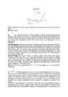
Ticket No1 1)The characteristic is called output characteristic or volt-ampere charateristic of a Rectifier Diode. 2)Rectifier Diode. 3) A is called Anode and C is called Cathode. An Anode has positive potential and therefore collects electrons in the device. Cathode has negative potential and therefore emits electrons to anode. The symbol looks like an arrow that ponts from the anode to the cathode, and reminds that conventional current flows easily from the p side(anode) to the n side(cathode). BIASING. Forward biasing. If the current in a diode is too large, excessive heat will destroy the device. Even approaching the burnout current value without reaching it can shorten its life. Therefore manufacturer's data sheet specifies the maximum forward current, that diode can withstand. This average current IF is the rate a diode can handle up to the forward direction when used as a rectifier. Another entry of interest in the da
Thesis “How is it possible to calculate IT security effectiveness?” Kristjan Kivimaa August 2022 1 Abstract In IT Security world, there is lack of available, reliable systems for measuring security levels/posture. They lack the range of quantitative measurements and easy and fast deployment, and potentially affects companies of all sizes. Readily available security standards provide qualitative security levels, but not quantitative results – that would be easily comparable. This deficiency makes it hard for companies to evaluate their security posture accurately. Absence of security metrics makes it complicated for customers to select the appropriate measures for particular security level needed. The research question for this research project is – “How is it possible to calculate IT security effectiveness?”. The aim of this research is to use this reference m
Voyage Planning Voyage Planning The key elements of the Voyage Plan are: Appraising all relevant information Planning the intended voyage Executing the plan taking account of prevailing conditions Monitoring the vessel’s progress against the plan continuously Planning The detailed voyage or passage plan should include the following factors: 1) the plotting of the intended route or track of the voyage or passage on appropriate scale charts: the true direction of the planned route or track should be indicated, as well as all areas of danger, existing ships' routeing and reporting systems, vessel traffic services, and any areas where marine environmental protection considerations apply; 2) the main elements to ensure safety of life at sea, safety and efficiency of navigation, and protection of the marine environment during the intended voyage or passage; such elements should include, but not be limited
Facts about charts and carriage requirements Primar Stavanger – IC-ENC Working Group on information (PSIWG) 1st edition - November 2004 Kort & Matrikelstyrelsen Graphic design: Peter M. Bastrup, KMS This compendium may be reproduced in whole or in part provided that all extracts quoted are reproduced verbatim without adaptation and the source and date are stated. Primar Stavanger and IC-ENC shall be indentified as the originators of the compendium. 2 Facts about chart carriage reguirements CONTENTS Introduction . . . . . . . . . . . . . . . . . . . . . . . . . . . . . . . . . . . . . . . . . . . . . . . . . . . . . . . . . .4 Where are the rules for professional marine navigation written down? . . . . . . . . . . .6 What are the IMO requirements for the carriage of nautical charts? . . . . . . . . . . . . .6 What is a nautical chart? . . .


Kõik kommentaarid