Vajad kellegagi rääkida?
Küsi julgelt abi LasteAbi
Logi sisse

Subject Paper (0)

1 Hindamata
Punktid

TABLE OF CONTENTS  INTRODUCTION  ..................................................................................................................................... 2  

1   METHOD  OF  DIRECT  MEASUREMENTS OF DIMENSIONS AND DISTANCES OF SHAFT 

WALLS  ..................................................................................................................................................... 3   2   3D SCANNING ................................................................................................................................ 5   2.1   Polar  method ............................................................................................................................... 5   2.2   Method of terrestrial laser scanning ........................................................................................... 6   SUMMARY .............................................................................................................................................. 8   CITED   SOURCES  .................................................................................................................................... 9    

2    INTRODUCTION 

When  an  elevator  shafts  has  been   built   or  it  is   going   to  be  renovated  the  engineers  need  precise  dimensions and accurate  understanding  of  actual    conditions . Engineers will use  plans  and all the data  they  already  have, but the measurement on the plan may not be the  same  as in  real -life  condition . They  need  the  accurate  dimensions  to  validate  the  plan   accuracy .  That’s  why  it  is  always   necessary   to  remeasure all the dimensions.   Today  we have more and more  ways  how to  measure  dimension. The  traditional  way is to use  simple   measure tape and human resources. But  these   days   there  are  easier  and  quicker  ways how to measure,  than  the traditional way. More  devices  and precise  technology  have been  brought  in use. But will it be  faster  and easier than a real human job, what has been in use for  centuries . Can we  really   relay  on devices? 

3    1  METHOD OF DIRECT MEASUREMENTS OF DIMENSIONS 

AND DISTANCES OF SHAFT WALLS  The  traditional   process   for  acquiring  an  as-built   reading   of  an  elevator  shaft   requires   engineers  to  go  floor - by-floor  with  a  measuring  tape  to   survey   the   width   of  the  shaft  at  each  floor  opening.  These  measurements  capture  the  changes  in the shaft width from floor-to-floor,  providing  subcontractors with  the necessary information to  assess  how far off the  wall  they need to shim the rails to  ensure  they are  perfectly straight  for the elevator to run smoothly through the shaft. [1]  In detail, the method of direct measurements of dimensions and distances of shaft walls from a fixated  plummet as the simplest measuring method. The plummet with a  weight  of about 1 kg will be placed to  a shaft wall  corner  of the elevator shaft on a bar  suspension  at the  eighth   storey  of the  object  (fig 1. and  2.). It will be fixated by immersing it in a  tank   filled  with oil at the level of the  first  storey. The dimensions  of the elevator shaft and the  distance  of the walls from the plummet  hanging  will be measured directly  using a measuring tape, and in  case  of non-accessible locations, using the  manual  laser telemeter. The  average   error  of  length  measurements, declared by the  instrument  manufacturer, is md = ±1,5mm. The  dimensions and the distances will be measured at each storey at a  height  of 1.40 m  above  the level of the  entry plane  of the elevator. [2]     Figure  1. Plummet hanging [2]  Figure 2. Plummet hanging [2] 
4      Not only does the traditional surveying process take a long time, but it also  puts   workers  at risk every  time they have to  access  a floor opening.  Even  more, traditional surveying only captures a fraction of the  elevator  shaft  information.  For  example,  with  traditional  surveying  we  are  only  obtaining  the  measurements at the floor openings, not in between floors . [1] 

5    2  3D SCANNING 

When surveying the elevator shafts, 3D laser scanning can also be used. Using a 3D laser scanning will  be faster and easier way to survey and measure elevator shafts. Also, it reduces  engineer ’s  safety  risks,  reduces the time it takes to survey and captures 100% of the elevator shaft data.    2.1  Polar method  Polar  method  with  exploiting  the  UMS   Leica   TCRA  1201+  (Fig  3.),  the  average  measuring  error  of  vertical   and  horizontal   angles   mα=mz=±1´´,  the   mean   error  of  length  measurements  with  a   prism   md=±1mm+1,5ppm  and   without   a  prism  md=±2mm+2ppm.  The   positions   of  the  instrument  will  be  selected  for  each  storey  to  be   possible   to  measure  the   maximum   number  of   points    along   the  shaft  circumference  at  a  height  of  1.40  m  above  the  level  of  the  entry  plane  of  the  elevator.   During   the  measurements,  the  method  of  subordinate  centring  on  tripods  will  be   applied .  The  determination  of  coordinates at each storey will be executed in the coordinate system of a staking  grid  of the  construction   (S-JTSK). For the backward orientation of measurements always the same point at a distance of about  70 mm may be used. At each storey,  beside  the  visible  edges without a prism, also the shaft walls will  be  measured.  The  edges,  which   could   not  be  measured  directly  from  the  site  as  they  were  in  the  obstruction of the walls, will be constructed in the prolongation of the points on the walls as intersections  of  approximated   lines   of  the  flowlines  of  the  measured  points.  For  the   purpose   of  checking,  also  the  plummet hanging will be positional measured at each storey with the use of a  reflection foil  and later  on  with the use of a 360° mini prism. [2]    Figure 3. TCRA 1201+ [2] 

6    2.2  Method of terrestrial laser scanning 

Method of terrestrial laser scanning with the use of TLS Leica ScanStation C10 (Fig.4. and 5.). The mean  error of determination of an  individual  point  position  mp=±6mm, the mean error of length measurements  md=±4mm (for the lengths up to 50 m), the mean error of measurements of horizontal and vertical angles  mα=mz=±12´´, the accuracy of the modelled  surface  mm=±2mm. The instrument is furnished with a  two- axis   compensator  with  the  accuracy  of  ±1,5´´  and  a  range  of  ±5´  (Leica  ScanStation  C10  –  data  sheet). The measurements will be conducted at the same time from one position at the  lowest  storey of  the  building  object at the  bottom  of the elevator shaft. The horizontal and vertical  density  of the measured  points will be adjusted to 5mm per each 25m of length. The TLS method is an up to  date  and efficient  method for collecting spatial data on objects.[2]  But it is necessary to  scan  on every storey of the elevator. This can´t be  done  without huge safety risk, to  prevent it, engineers have  come up with the solution .   The engineers can  craft  an outrigger arm to  safely   hold  the  scanner  in the  middle  of the elevator shaft.  By using the outrigger arm, the engineers will be  able  to  keep  safety barriers in  place  on each floor. And,  because  it  will  no   longer   be  necessary  to  secure   team    members   in  safety  harnesses   while   surveying  elevator shafts, a  major  risk will be eliminated in the process.[1]  Using the outrigger arm design, it will be able to scan three to  four  floors at a time, significantly cutting  down the time it takes to survey an elevator shaft. In this  manner , the laser scanner is able to capture a  Figure 4. TLS Leica Scan Stantion C10 [2]  Figure 5. TLS Leica Scan Stantion C10 [2] 
7    complete  reading of the  entire  elevator shaft, cataloguing 100  percent  of the dimensions for accurate, information - rich , as-built  documents . With the complete dimensions of the elevator shaft measured, the  engineers   upload   the  scans  into  3D  laser  scanning  software.  The   result   is  an  as-built   document   that  captures 100 percent of the dimensional information about the elevator shaft for subcontractors to then  assess and ensure rails are accurately installed.[1]  

8    SUMMARY 

Construction and design plans are  usually   ideal , but the actual  outcome  and conditions will not be precise.  Generally, these incompatibilities will  turn  up a point at which re-design and re- work  are  difficult  and  costly . It is necessary to remeasure all the dimensions. There are many ways how it can be done. As we  have  found out some methods are more efficient than others .   The traditional way to measure elevator shafts will  stay   among  new methods, but it takes unnecessary  risks and too much time. The new methods are more accurate, time and risk  saving  to use. Also, with  laser scanning, an engineer can capture a  clear , thorough and accurate understanding of actual conditions,  and validate that the new design  fits  the existing conditions  prior  to construction. When comparing two  methods of laser scanning, I think the method of terrestrial laser scanning is more  reasonable  and we can  relay on it even more.        

9    CITED SOURCES 

[1]  „Laser-Scanning-Elevator-Shafts-Case- Study - FINAL -for-Web-(12_18_15).pdf“.  Vaadatud:  19.  jaanuar 

2022 .  [Online].  Available   at:  https://balfourbeattyus.com/Balfour-

dev.allata.com/media/content-media/pdfs/Laser-Scanning-Elevator-Shafts-Case-Study-FINAL-for- Web-(12_18_15).pdf  [2]  Ľ. Kovanič, „Determination of Elevator Shaft Uprightness  Applying  the Terrestrial Laser Scanning  Method / Určovanie Zvislosti Výťahovej Šachty Metódou Terestrického Laserového Skenovania“,  Geosci. Eng., kd 59, sept 2013, doi: 10. 2478 /gse-2014-0059.   
Vasakule Paremale
Subject Paper #1 Subject Paper #2 Subject Paper #3 Subject Paper #4 Subject Paper #5 Subject Paper #6 Subject Paper #7 Subject Paper #8 Subject Paper #9
Punktid Tasuta Faili alla laadimine on tasuta
Leheküljed ~ 9 lehte Lehekülgede arv dokumendis
Aeg2022-03-01 Kuupäev, millal dokument üles laeti
Allalaadimisi 0 laadimist Kokku alla laetud
Kommentaarid 0 arvamust Teiste kasutajate poolt lisatud kommentaarid
Autor lisbetr Õppematerjali autor

Sarnased õppematerjalid

Laser scanning elevator shafts
9
pdf

Laser scanning elevator shafts

TABLE OF CONTENTS INTRODUCTION ..................................................................................................................................... 2 1 METHOD OF DIRECT MEASUREMENTS OF DIMENSIONS AND DISTANCES OF SHAFT WALLS ..................................................................................................................................................... 3 2 3D SCANNING ................................................................................................................................ 5 2.1 Polar method ............................................................................................................................... 5 2.2 Method of terrestrial laser scanning ........................................................................................... 6 SUMMARY ..............................................................................................................................................

Hoonete 3D laserskaneerimine
Kuidas muudab mudelprojekteerimine teraskonstruktsioonide valmistamist ja ehitamist
228
pdf

Kuidas muudab mudelprojekteerimine teraskonstruktsioonide valmistamist ja ehitamist

conditions. Finally, one of the biggest issues facing the construction industry, is the inability to discern constructability problems during the preconstruction phase of a project (Mitchell, 2009). To understand the effects that three-dimensional building information models are having on the design, fabrication and construction of steel structures, it is important to understand how the structural steel components that make up a building’s frame are created. A paper by Autodesk on “BIM and Digital Fabrication” describes the steel fabrication process: First a steel mill uses a hot-rolling manufacturing process to create stock structural steel members. This stock material is purchased by steel fabricators who cut and prepare the stock structural beams and columns for building construction based on shop drawings – instructions that describe exactly how to fabricate each individual piece of a structure.

Ehituskonstruktsioonid
Book Analog Interfacing to Embedded Microprocessors
568
pdf

Book Analog Interfacing to Embedded Microprocessors

Copyright © 2001 by Butterworth–Heinemann A member of the Reed Elsevier group All rights reserved. No part of this publication may be reproduced, stored in a retrieval system, or transmitted in any form or by any means, electronic, mechanical, photocopying, recording, or otherwise, without the prior written permission of the publisher. Recognizing the importance of preserving what has been written, Butterworth–Heinemann prints its books on acid-free paper whenever possible. Library of Congress Cataloging-in-Publication Data Ball, Stuart R., 1956– Analog interfacing to embedded microprocessors : real world design / Stuart Ball. p. cm. ISBN 0-7506-7339-7 (pbk. : alk. paper) 1. Embedded computer systems—Design and construction. 2. Microprocessors. I. Title. TK7895.E42 .B33 2001 004.16—dc21 00-051961 British Library Cataloguing-in-Publication Data

Mehhatroonika
Total station problems
4
pdf

Total station problems

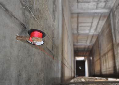
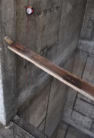
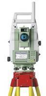
Laura Lüll KRG11/21 Total station: Problems 1. Distinguish between transits and theodolites. - Transits and theodolites are instruments for measuring horizontal and vertical angles. The distinction between these instruments is not very clear. At first, both of instruments were called theodolites. The instruments that were manufactured with long telescopes and could not be inverted end for end were called theodolites. As technology developed, people started making instruments with shorter telescopes that could be inverted or transited – these machines were called transits. Time went on and in the end most instruments – both theodolites and transits were manufactured with telescopes witch could be inverted. Now, the original distinction is no longer

inglise teaduskeel
3D Kordamine 2021
6
pdf

3D Kordamine 2021

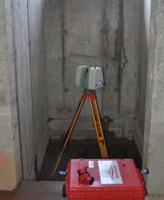
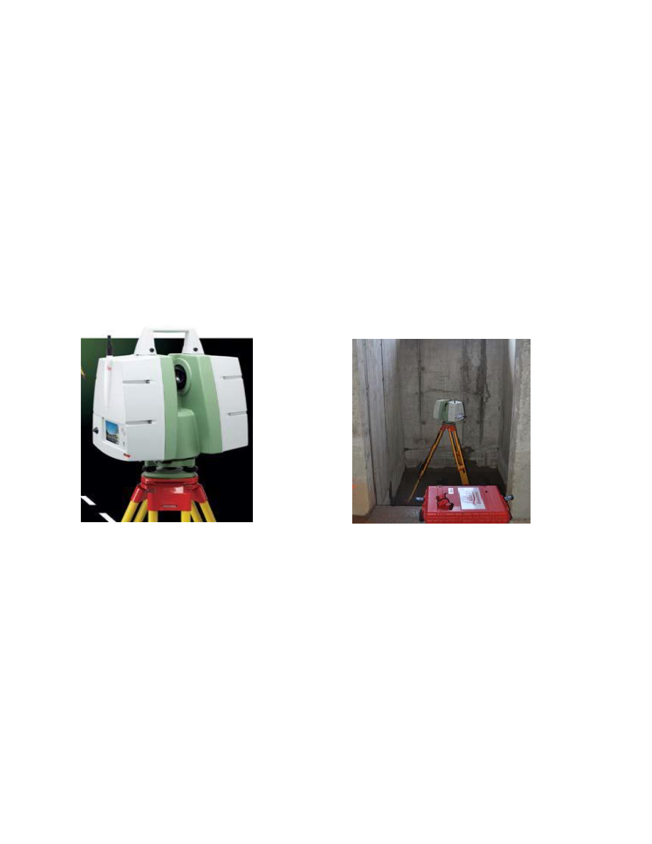
Chapter 1. Introduction and Chapter 2. Lasers. 1. Name the common data collecting technologies. Contact and non contact. Non contact separaate to active and passive scanners. 2. Describe the data collected by laser scanning. Its land surveying method what measure and collect data from objects, surfuce, buildings, and landscapes. Laser scanning collects information from point cloud data witch consists of milions of 3D cordinates(XYZ) 3. What is Remote Sensing? 3D laser scanning is a remote sensing technology that uses laser technology to survey the surrounding environment. 4. Name Remote Sensing technologies. Depending on the scanning platform 3D laser scanning can be divided into: Airborn also reffered as ALS. A land based aka terrestrial , Static/Dynamic TLS 5. What do the acronyms TLS, MTLS, ALS, LIDAR, LASER, TOF, PS refer to? TLS (TerrestriaTLS (Terrestrial Laser Scanning) - viitab otseselt maapealsele,

Hoonete 3D laserskaneerimine
Vormistamine ülesanne 3
18
docx

Vormistamine ülesanne 3

of members of a small professional association. Others are incredibly complex, such as a survey of the general public across all countries of the European Union in which the same questions need to be answered in multiple languages by people of all educational levels. In the mid-twentieth century there was a remarkable similarity of survey procedures and methods. Most surveys of significance were done by face-toface interviews in most countries in the world. Self-administered paper surveys, usually done by mail, were the only alternative. Yet, by the 1980s the telephone had replaced face-to-face interviews as the dominate survey mode in the United States, and in the next decade telephone surveys became the major data collection method in many countries. Yet other methods were emerging and in the 1990s two additional modes of surveying— 3

Andme-ja tekstitöötlus
Thesis Kivimaa August 2022
140
pdf

Thesis Kivimaa August 2022

Thesis “How is it possible to calculate IT security effectiveness?” Kristjan Kivimaa August 2022 1 Abstract In IT Security world, there is lack of available, reliable systems for measuring security levels/posture. They lack the range of quantitative measurements and easy and fast deployment, and potentially affects companies of all sizes. Readily available security standards provide qualitative security levels, but not quantitative results – that would be easily comparable. This deficiency makes it hard for companies to evaluate their security posture accurately. Absence of security metrics makes it complicated for customers to select the appropriate measures for particular security level needed. The research question for this research project is – “How is it possible to calculate IT security effectiveness?”. The aim of this research is to use this reference m

Infotehnoloogia
Integration of Lean Con-and Building Information Modelling
109
pdf

Integration of Lean Con. and Building Information Modelling

Ergo Pikas Integration of Lean Construction and Building Information Modelling DISSERTATION Tallinn 2010 2 UNIVERSITY OF APPLIED SCIENCES Author: Ergo Pikas- Civil Engineering student, Faculty of Construction, Tallinn University of Applied Sciences Supervisor: Rafael Sacks- Associate Professor, Faculty of Civil and Env. Engineering, Technion ­ Israel Institute of Technology Consultant: Roode Liias- Professor and Dean, Faculty of Civil Engineering, Tallinn University of Technology Title: Integration of Lean Construction and Building Information Modelling Archived: University of Applied Sciences, Faculty of Construction ABSTRACT This research can be divided into two. The first part investigates the current state of the construction industry, while the second part looks at new emerging busin

Ehitusjuhtimine


Meedia

Kommentaarid (0)

Kommentaarid sellele materjalile puuduvad. Ole esimene ja kommenteeri


Sellel veebilehel kasutatakse küpsiseid. Kasutamist jätkates nõustute küpsiste ja veebilehe üldtingimustega Nõustun