Vajad kellegagi rääkida?
Küsi julgelt abi LasteAbi
Logi sisse

Mikrokontrollerid ja robootika homework 2 (0)

1 Hindamata
Punktid


Question 1 
Define the  following  ADC  terms
1.  SNR – ( Signal to Noise  Ratio ) SNR is a calculated value  that represents the ratio of RMS 
signal to RMS noise. 
2.  SINAD - (signal-to-noise-and-distortion ratio) Ratio of the RMS signal amplitude to the 
mean  value of the root -sum- square  (RSS) 
3.  ENOB – (effective number of bits ) The effective number-of-bits and relates to SINAD 
4.  THD - ( total harmonic distortion) Ratio of the rms value of the  fundamental  signal to 
the mean value of the RSS of its harmonics. 
5.  SFDR - ( spurious free  dynamic  range) Ratio of the RMS value of the signal to the RMS 
value of the worst spurious signal. 
6.  Channels -  related to the inputs of the ADC can either be multiplexed or individually 
selected. 
7.  Linearity - relates to how a ADC follows a linear function . All ADCs are to a certain 
extend nonlinearity. 
8.   Operating  temperature - measurement, which in optimal state for ADC-s, lets 
them  function correctly. 
9.   Power  dissipation - refers to the  amount  power dissipated when the ADC is 
operating. 
 
 
Question 2 
 
An 8 bit ADC has a  reference   voltage  of 5V. What is the  digital  output 
code  word for an input of 1.2V? What is the voltage range 
corresponding to 1 LSB? 
1,2𝑉
= 61 ; 61 = 001111012 
0,0195𝑉
Digital output code for an input of 1.2V is 001111012. 
Voltage range corresponding to 1 LSB is U= 0,0195V. 
Question 3 
 
A 15 bit ADC has a reference voltage of 10V. What is the digital 
output code word for an input of 6.83V? 
 
15 bit = 32768 
10V/ 32768 = 0,0003 V 
6,83V / 0,0003 = 22767         22767 = 01011000 111011112 
 
 
Question 4 
 
What is the value of the quantization error  between an input voltage of 
2.3V and quantized voltage with the output code word equal to 
011101012 using an 8 bit ADC with 5V reference? 
 
011101012 = 117 
Correspond to 5V * 117/256 = 2.2852V 
Error = 2,3V – 2.2852 = 0,0148V
Question 5 
 

A digital multimeter is designed to have a readout with four decimal 
digits. How many bits will be required in its ADC? 
 
MAX = 9999 
213 = 8192    214 = 16384 (too many digits) 
13 Bit will be required in ts ADC. 
 
Question 6 
 
Draw  a  circuit  diagram of a 2 bit  flash  ADC using only resistors, 
comparators and  NAND  gates. 


Question 7 
Given the following  dual - slope  ADC: 


a)  How long would it take for this ADC to  complete  the run-up 
phase? 
𝑅𝐶
𝑡𝑢𝑝 =   −
  ∙ 𝑉
𝑉
𝑜𝑢𝑡 =   −400𝜇𝑠  
𝑖𝑛
The run-up phase  takes  400 μs. 
b)  How long would it take for this ADC to complete the run-down 
phase? 
𝑡𝑑𝑜𝑤𝑛 =   (𝑉𝑖𝑛  ∙ 𝑡𝑢𝑝)/ −𝑉𝑟𝑒𝑓 = 0,001 = 1𝑚𝑠  
The run-down phase takes 1 ms.
Question 8 
What is the typical performance in terms of THD at a frequency  of 500 kHz of: 
 
a)  MAX1200  pipeline  ADC. -85dB 
b)  MAX1201 pipeline ADC. -85dB 
c)  MAX1205 pipeline ADC. -84dB 
 
 
Question 9 
Name two  disadvantages  of: 
a)  Flash ADC -  expensive , high power consumption 
b)  SAR ADC -  speed  is limited,  needs  anti-aliasing filter 
c)  Dual-slope ADC - slow  conversion, expensive external components required (high 
accuary components) 
a)  Sigma  Delta  ADC -multibit ADC and multibit feedback DAC –  higher   order  
 
 
Question 10 
Find the following for the  built -in ADC in the PIC18F45K20: 
a)  Architecture  - SAR(Succesive Approximation  Register
b)  Differential linearity - +- 0.4 LSB 
c)  Minimum acquisition time – 1.4ms 
d)  Minimum conversion time – 8.4 𝜇𝑠 
 
 
Question 11 
A 10 bit DAC has a reference voltage of 5.12V. What is the output 
voltage for a  binary  input code of 11000100012? 
 
11000100012 = 785 
210 = 1024 
(5.12/ 1024) * 785 = 3.925V 
 
Output voltage = 3.925V
Question 12 
A 12 bit DAC has a reference voltage of 10V. What is the output 
voltage for a binary input code of 1001001001002? 
 
1001001001002 =  2340  
212 = 4096 
(10 / 4096) * 2340 = 5.71 V 
 
Output voltage = 5,71 V 
 
Question 13 
What is the resolution of a 16-Bit DAC? 
 
216 = 65536 
Question 14 
Name 5 characteristics of DAC’s. 
 
1.   Gain  error 
2.  Offset error 
3.  Resolution 
4.  Monotonicity 
5.  Accurary(relative) 
Question 15 
For the following 3-Bit DAC,  analyse  the circuit to verify its  operation  
for the following input combinations. (Assume VR=5V). 
a)S2S1S0=0102   Output voltage = 1.25 V  
b)S2S1S0=1012     Output voltage = 3,125 V   
c)S2S1S0=0112   Output voltage = 1.875 V 


Question 16 
 
Pulse- Width   Modulation  (PWM)  is  a   commonly   used  technique 
for  controlling  power to inertial electrical  devices  and DC motors. 
The  PWM  switching  frequency  has  to  be  much  faster   than   what 
would affect the load  on DC motors. 
 
1. Draw  the   motor   current  and  the  motor  voltage   characteristic  
during the operation with a  constant  PWM signal of 50% duty 
cycle


2. Recommend  the   suitable   range  of  frequency  for  this  PWM 
applied  in  microcontrollers.  Analyze  the  advantages  and 
disadvantages of PWM systems. 
 
The frequency should be about 30kHz, voltage 5V. 
 
The advantages of PWM systems: 
Very high efficiency (not much heat  produced) 
Relatively  cheap  
Makes the motor run smoother 
 
The disadvantages of PWM systems: 
PWM circuits are complicated 
Sensitive to electromagnetics and  could  interfere with radio  signals , cause vibration 
frequencies, which cause noises. 
Vasakule Paremale
Mikrokontrollerid ja robootika homework 2 #1 Mikrokontrollerid ja robootika homework 2 #2 Mikrokontrollerid ja robootika homework 2 #3 Mikrokontrollerid ja robootika homework 2 #4 Mikrokontrollerid ja robootika homework 2 #5 Mikrokontrollerid ja robootika homework 2 #6 Mikrokontrollerid ja robootika homework 2 #7
Punktid 10 punkti Autor soovib selle materjali allalaadimise eest saada 10 punkti.
Leheküljed ~ 7 lehte Lehekülgede arv dokumendis
Aeg2016-03-01 Kuupäev, millal dokument üles laeti
Allalaadimisi 10 laadimist Kokku alla laetud
Kommentaarid 0 arvamust Teiste kasutajate poolt lisatud kommentaarid
Autor Hendrik Karhu Õppematerjali autor
Kodutöö 2, max punktid

Sarnased õppematerjalid

Homework 2 Week 4
12
docx

Homework 2 Week 4

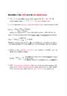
Week 4 homework. Question 1: 1. SNR – Ratio of root mean square signal to root mean square. 2. SINAD – Ratio of the RMS signal amplitude to the mean of value of the root sum square. 3. ENOB – The effective number of bits and relates to SINAD. 4. THD – Ratio of the rms value of the fundamental signal to the mean value of RSS of its harmonics. 5. SFDR – Ratio of the RMS value of the signal to the RMS value of the worst spurious signal. 6. Channels – multiple analog signal inputs to the ADC that can be individually selected or selected through a multiplexor. 7. Linearity – Describes how an ADC conveter follows a linear function. 8. Operating temperature – A temperature at which the ADC functions optimally, usually given by the manufacturer. 9. Power dissipation – The proportion of power dissipated (through heat) when the ADC is working. Question 2: An 8 bit ADC has a reference voltage of 5V. What is the digital output code word for an input of 1.2V? 0011

Inglise keel
Microcontroller homework 2
2
docx

Microcontroller homework 2

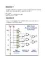
Microcontroller homework for week 04 1. SNR - Ratio of RMS signal to RMS SINAD - Ratio of the RMS signal amplitude to the mean value of the root-sum-square (RSS) ENOB - The effective number-of-bits and relates to SINAD THD - Ratio of the rms value of the fundamental signal to the mean value of the RSS of its harmonics. SFDR - Ratio of the RMS value of the signal to the RMS value of the worst spurious signal. Channels related to the inputs of the ADC can either be multiplexed or individually selected. Linearity relates to how a ADC follows a linear function. All ADCs are to a certain extend non-linearity. Temperature is measurement, which in optimal state for ADC-s, lets them function correctly. Power dissipation refers to the amount power dissipated when the ADC is operating. 2. The output code is 001111012 and the voltage of the LSB is 0,0195V 3. The output code is 101011101101100 4. The

Mikrokontrollerid ja praktiline robootika
Homework 2 Solution
12
pdf

Homework 2 Solution

Question 1 (in wiki and in terminologies) 1. SNR is a calculated value that represents the ratio of root- mean-square (rms ) signal to rms noise. 2. SINAD stands for Signal-to-noise and distortion ratio. It is a measure of the quality of a signal from a communications device, often defined as: where is the average power of the signal, noise and distortion components. SINAD is usually expressed in dB. For examples to calculate the ratio of 1 kW (one kilowatt, or 1000 watts) to 1 W in decibels, use the formula 3. ENOB is the effective number-of-bits related to SINAD and the quality of a digitized signal. The 6.02 term in the divisor converts decibels (a log10) to bits (a log2) The 1.76 term comes from quantization error in an ideal ADC 4. THD - Total harmonic distortion is the ratio of the root-mean-square (rms) value of the fundamental signal to the mean value

Mehhatroonika
Book Analog Interfacing to Embedded Microprocessors
568
pdf

Book Analog Interfacing to Embedded Microprocessors

Analog Interfacing to Embedded Microprocessors Real World Design Analog Interfacing to Embedded Microprocessors Real World Design Stuart Ball Boston Oxford Auckland Johannesburg Melbourne New Delhi Newnes is an imprint of Butterworth–Heinemann. Copyright © 2001 by Butterworth–Heinemann A member of the Reed Elsevier group All rights reserved. No part of this publication may be reproduced, stored in a retrieval system, or transmitted in any form or by any means, electronic, mechanical, photocopying, recording, or otherwise, without the prior written permission of the publisher. Recognizing the importance of preserving what has been written, Butterworth–Heinemann prints its books on acid-free paper whenever possible. Library of Congress Cataloging-in-Publication Data Ball, Stuart R., 1956– Analog interfacing to embedded microprocessors : real world design / Stuart Ball. p. cm. ISBN 0-7506-7339-7 (pbk. : alk. paper) 1. Embedded computer

Mehhatroonika
Mikrokontrollerid ja robootika kodutöö 3
14
docx

Mikrokontrollerid ja robootika kodutöö 3

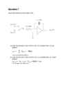
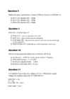
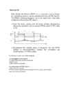
output voltage for a relative humidity of 70 % at 30 °C if R T = 50 kΩ and VDD= 2.5 V. R70 30 c =R H =9,2 kV RH 9,2 k V O= ∙ V DD= ∙ 2,5 = 0,388 V (R T + R H ) ( 50 k +9,2 k ) Hint: Check specification for Humidity Sensor of SYH-2R.pdf at http://www.rhopointcomponents.com/images/SYH-2R.pdf 2 Week 04 Homework Question 3 Given the following bridge circuit for a strain gauge, determine the value of the strain gauge resistance {RS}. Let: VIN = 5V R3 = 200 Ω R2 = 50 Ω R1 = 100 Ω a) Under no strain (VOUT = 0 V) R2 ∙ R3 RS= =100 Ω R1 b) When VOUT = 0,5 V {under strain}. 100 200 0,1= − 150 200+ RS 200 200 0,56= =¿> RS= −200=¿> RS=157 Ω 200+ RS 0,56 RS ≈157 Ω

Mikrokontrollerid ja robootika
W05 Homework3 Solutions
20
pdf

W05 Homework3 Solutions

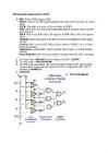
Solution: 1. Thershold. 2. Sensitivity. 3. Full Range. 4. Linearity. 5. Accuracy. 6. Precision. 7. Stability. 8. Hysteresis. 9. Noise. Question 2 Given the circuit below (using a SYH-2R humidity sensor) determine the output voltage for a relative humidity of 70 % at 30 °C if RT = 50 kΩ and VDD= 2.5 V. Solution: Check specification for Humidity Sensor of SYH-2R.pdf at: http://www.rhopointcomponents.com/images/SYH-2R.pdf 2 Week 04 Homework - Solutions Check Thermistor - Wikipedia.pdf at http://en.wikipedia.org/wiki/Thermistor Calculate the Humidity Sensor resistance at 30°C T = 273.15°C +30°C = 303.15°C T0 = 273.15°C +25°C = 298.15°C R60% 30°C =25.5858 kΩ - Matlab code: 33*exp(4600*(1/303.15-1/298.15)) = 25.5858 Calculate the Humidity Sensor resistance at relative humidity 70% See the above graphic for the standard resistance: Exercises - Solutions 3

Mehhatroonika
Electrical drives and power electronics
5
docx

Electrical drives and power electronics

Electrical drives and power electronics TESTS · The synchronous machines are associated with the names of Ferraris · Name the scientists who first studied electrical phenomena Coulomb · The DC machines are associated with the names of Jacobi Henry · The leading companies in the world market of electrical drive engineering are Mitsubishi · · The electromagnetic torque is born in air gap · What kind of drives the majority of drive systems present low accuracy · The induction machines are associated with the names of Dolivo-Dobrovolsky Tesla · One of the first eletrical motors has been built by Jacobi · Electromagnetic efficiency is measured in tesla · Time constants are measured by ms s hours · Who is the author of the first electrical motor Henry · Which rectifier cannot be built without a transformer 3-phase midpoint · Call the benefits of 3-phase rectifiers upon the 1-phase ones output voltage · Which rectifier has more diodes 3-phase bridge · In th

Elektriajamid
CPM1A Programmable Controllers Operation Manual 1784470
402
pdf

CPM1A Programmable Controllers Operation Manual 1784470

Cat. No. W317-E1-11 SYSMAC CPM1A Programmable Controllers OPERATION MANUAL CPM1A Programmable Controllers Operation Manual Revised October 2007 iv Notice: OMRON products are manufactured for use according to proper procedures by a qualified operator and only for the purposes described in this manual. The following conventions are used to indicate and classify precautions in this manual. Always heed the information provided with them. Failure to heed precautions can result in injury to people or dam- age to property. ! DANGER Indicates an imminently hazardous situation which, if not avoided, will result in death or serious injury. Additionally, there may be severe property damage. ! WARNING Indicates a potentially hazardous situation which, if not avoided, could result in death or serious inju

Automatiseerimistehnika


Meedia

Kommentaarid (0)

Kommentaarid sellele materjalile puuduvad. Ole esimene ja kommenteeri


Sellel veebilehel kasutatakse küpsiseid. Kasutamist jätkates nõustute küpsiste ja veebilehe üldtingimustega Nõustun