Question 1 Define the following ADC terms: 1. SNR – (Signal to Noise Ratio) SNR is a calculated value that represents the ratio of RMS signal to RMS noise. 2. SINAD - (signal-to-noise-and-distortion ratio) Ratio of the RMS signal amplitude to the mean value of the root-sum-square (RSS) 3. ENOB – (effective number of bits) The effective number-of-bits and relates to SINAD 4. THD - (total harmonic distortion) Ratio of the rms value of the fundamental signal to the mean value of the RSS of its harmonics. 5. SFDR - (spurious free dynamic range) Ratio of the RMS value of the signal to the RMS value of the worst spurious signal. 6. Channels - related to the inputs of the ADC can either be multiplexed or individually selected. 7. Linearity - relates to how a ADC follows a linear function. All ADCs are to a certain extend nonlinearity. 8. Operating temperature - measurement, which i
Week 4 homework. Question 1: 1. SNR – Ratio of root mean square signal to root mean square. 2. SINAD – Ratio of the RMS signal amplitude to the mean of value of the root sum square. 3. ENOB – The effective number of bits and relates to SINAD. 4. THD – Ratio of the rms value of the fundamental signal to the mean value of RSS of its harmonics. 5. SFDR – Ratio of the RMS value of the signal to the RMS value of the worst spurious signal. 6. Channels – multiple analog signal inputs to the ADC that can be individually selected or selected through a multiplexor. 7. Linearity – Describes how an ADC conveter follows a linear function. 8. Operating temperature – A temperature at which the ADC functions optimally, usually given by the manufacturer. 9. Power dissipation – The proportion of power dissipated (through heat) when the ADC is working. Question 2: An 8 bit ADC has a reference voltage of 5V. What is the digital output code word for an input of 1.2V? 0011
Microcontroller homework for week 04 1. SNR - Ratio of RMS signal to RMS SINAD - Ratio of the RMS signal amplitude to the mean value of the root-sum-square (RSS) ENOB - The effective number-of-bits and relates to SINAD THD - Ratio of the rms value of the fundamental signal to the mean value of the RSS of its harmonics. SFDR - Ratio of the RMS value of the signal to the RMS value of the worst spurious signal. Channels related to the inputs of the ADC can either be multiplexed or individually selected. Linearity relates to how a ADC follows a linear function. All ADCs are to a certain extend non-linearity. Temperature is measurement, which in optimal state for ADC-s, lets them function correctly. Power dissipation refers to the amount power dissipated when the ADC is operating. 2. The output code is 001111012 and the voltage of the LSB is 0,0195V 3. The output code is 101011101101100 4. The
Analog Interfacing to Embedded Microprocessors Real World Design Analog Interfacing to Embedded Microprocessors Real World Design Stuart Ball Boston Oxford Auckland Johannesburg Melbourne New Delhi Newnes is an imprint of Butterworth–Heinemann. Copyright © 2001 by Butterworth–Heinemann A member of the Reed Elsevier group All rights reserved. No part of this publication may be reproduced, stored in a retrieval system, or transmitted in any form or by any means, electronic, mechanical, photocopying, recording, or otherwise, without the prior written permission of the publisher. Recognizing the importance of preserving what has been written, Butterworth–Heinemann prints its books on acid-free paper whenever possible. Library of Congress Cataloging-in-Publication Data Ball, Stuart R., 1956– Analog interfacing to embedded microprocessors : real world design / Stuart Ball. p. cm. ISBN 0-7506-7339-7 (pbk. : alk. paper) 1. Embedded computer
Electrical drives and power electronics TESTS · The synchronous machines are associated with the names of Ferraris · Name the scientists who first studied electrical phenomena Coulomb · The DC machines are associated with the names of Jacobi Henry · The leading companies in the world market of electrical drive engineering are Mitsubishi · · The electromagnetic torque is born in air gap · What kind of drives the majority of drive systems present low accuracy · The induction machines are associated with the names of Dolivo-Dobrovolsky Tesla · One of the first eletrical motors has been built by Jacobi · Electromagnetic efficiency is measured in tesla · Time constants are measured by ms s hours · Who is the author of the first electrical motor Henry · Which rectifier cannot be built without a transformer 3-phase midpoint · Call the benefits of 3-phase rectifiers upon the 1-phase ones output voltage · Which rectifier has more diodes 3-phase bridge · In th
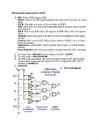
For this to occur, the Q point is located at cutoff on both the dc and ac load lines. Transistors are, because transistorized base bias is usually designed to operate in switching circuits by having either low output voltage or high output voltage.5)on circuits.6)Inverters output voltage is in the opposite polarity to the input voltage.Multiplexer is a multiple switch that steers one of the input signals to the output.Comparator:perfect solution for comparing one voltage with another to see which is larger.Latch:because the collector of T1 drives the base of T2 and vice versa,it is a positive feedback.Achange in current at any point of the loop is amplified and returned to the starting point with the same phase. 7)Advantages of swithces:Extremely low power consumption and lower heat production.Physically small.They can provide large load currents at low voltages although they produce more electrical and audible noise
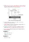
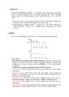
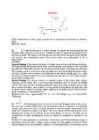
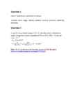
output voltage for a relative humidity of 70 % at 30 °C if R T = 50 kΩ and VDD= 2.5 V. R70 30 c =R H =9,2 kV RH 9,2 k V O= ∙ V DD= ∙ 2,5 = 0,388 V (R T + R H ) ( 50 k +9,2 k ) Hint: Check specification for Humidity Sensor of SYH-2R.pdf at http://www.rhopointcomponents.com/images/SYH-2R.pdf 2 Week 04 Homework Question 3 Given the following bridge circuit for a strain gauge, determine the value of the strain gauge resistance {RS}. Let: VIN = 5V R3 = 200 Ω R2 = 50 Ω R1 = 100 Ω a) Under no strain (VOUT = 0 V) R2 ∙ R3 RS= =100 Ω R1 b) When VOUT = 0,5 V {under strain}. 100 200 0,1= − 150 200+ RS 200 200 0,56= =¿> RS= −200=¿> RS=157 Ω 200+ RS 0,56 RS ≈157 Ω
Cat. No. W317-E1-11 SYSMAC CPM1A Programmable Controllers OPERATION MANUAL CPM1A Programmable Controllers Operation Manual Revised October 2007 iv Notice: OMRON products are manufactured for use according to proper procedures by a qualified operator and only for the purposes described in this manual. The following conventions are used to indicate and classify precautions in this manual. Always heed the information provided with them. Failure to heed precautions can result in injury to people or dam- age to property. ! DANGER Indicates an imminently hazardous situation which, if not avoided, will result in death or serious injury. Additionally, there may be severe property damage. ! WARNING Indicates a potentially hazardous situation which, if not avoided, could result in death or serious inju


Kõik kommentaarid