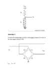
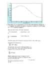
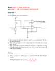
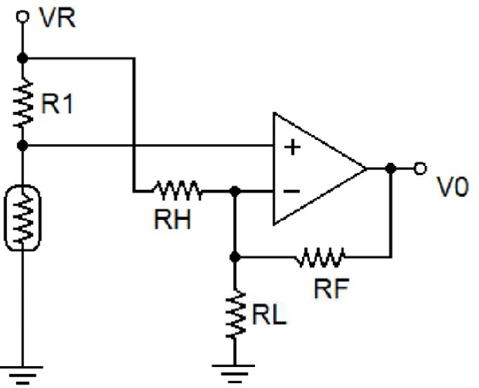
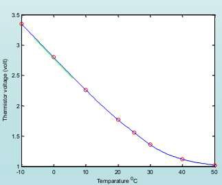
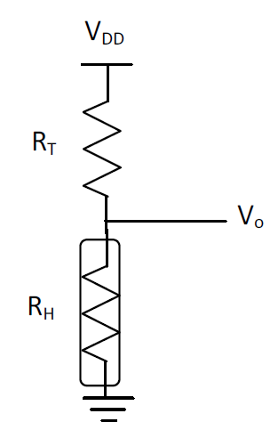
Question 1 Name 9 characteristic parameters of sensors. Solution: 1. Thershold. 2. Sensitivity. 3. Full Range. 4. Linearity. 5. Accuracy. 6. Precision. 7. Stability. 8. Hysteresis. 9. Noise. Question 2 Given the circuit below (using a SYH-2R humidity sensor) determine the output voltage for a relative humidity of 70 % at 30 °C if RT = 50 kΩ and VDD= 2.5 V. Solution: Check specification for Humidity Sensor of SYH-2R.pdf at: http://www.rhopointcomponents.com/images/SYH-2R.pdf 2 Week 04 Homework - Solutions Check Thermistor - Wikipedia.pdf at http://en.wikipedia.org/wiki/Thermistor Calculate the Humidity Sensor resistance at 30°C T = 273.15°C +30°C = 303.15°C T0 = 273.15°C +25°C = 298.15°C R60% 30°C =25.5858 kΩ - Matlab code: 33*exp(4600*(1/303.15-1/298.15)) = 25.5858 Calculate the Humidity Sensor resistance at relative humidity 70% See the above graphic for the standard resistance: Exercises - Solutions
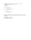
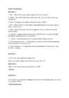
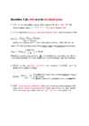
Midterm Exam Microcontrollers and Practical Robotics Question 1 Convert the decimal number 43.982 to (a) binary and (b) hex. Show all your calculations. a.) 101011.111110 b.) 2B.FB6 Question 2 Perform the calculation of 58 – 42 by first converting each decimal value to binary and then using the twos complement method. Show all your calculations 5810=001110102 4210=001010102 Converse to twos complement 4210=001010102=110101012+1=110101102 Then 58+(42) 001110102 +110101102 = 000100002 =1610 Question 3 Given the following bridge circuit for a strain gauge, determine the value of the strain gauge resistance {RS}. Let: VIN = 5V R3 = 100 Ω R2 = 50 Ω R1 = 100 Ω 2 Midterm Exam - Solutions a) Under no strain (VOUT = 0 V) b) When VOUT = 0,5 V {under strain}. Solution: a) Under no strain: R1 R3 R1R4 R2 R3 VOUT IN
Analog Interfacing to Embedded Microprocessors Real World Design Analog Interfacing to Embedded Microprocessors Real World Design Stuart Ball Boston Oxford Auckland Johannesburg Melbourne New Delhi Newnes is an imprint of Butterworth–Heinemann. Copyright © 2001 by Butterworth–Heinemann A member of the Reed Elsevier group All rights reserved. No part of this publication may be reproduced, stored in a retrieval system, or transmitted in any form or by any means, electronic, mechanical, photocopying, recording, or otherwise, without the prior written permission of the publisher. Recognizing the importance of preserving what has been written, Butterworth–Heinemann prints its books on acid-free paper whenever possible. Library of Congress Cataloging-in-Publication Data Ball, Stuart R., 1956– Analog interfacing to embedded microprocessors : real world design / Stuart Ball. p. cm. ISBN 0-7506-7339-7 (pbk. : alk. paper) 1. Embedded computer
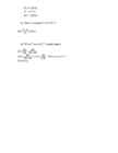
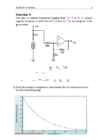
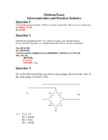
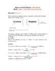
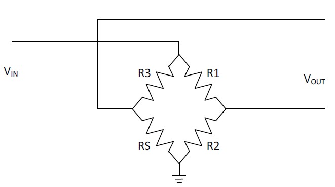
Read Chapter_6_Analog_Outputs.pdf and Chapter_8_EMI_ElectroMagnetic_Interference.pdf Question 1 Given the below open sensor detection: a. Derive equations for both outputs VO and Vsense as a function of VR, R1, Rth, RH, RL and RF. b. What value will appear on each output if the thermistor fails (becomes an open circuit)? c. How can the above schem be modified to implement temperature reading with open sensor detection using only one ADC and one digital input pin of the microcontroller? Solution: a. Derive equations for both outputs as a function of VR, R1, Rth, RH, RL and RF. Rth Writing the equation for V1 : V1 VSense VR th R R1 V0 V2 VR V2 V2 Writing the equation for V2 : RF RH
Week 4 homework. Question 1: 1. SNR – Ratio of root mean square signal to root mean square. 2. SINAD – Ratio of the RMS signal amplitude to the mean of value of the root sum square. 3. ENOB – The effective number of bits and relates to SINAD. 4. THD – Ratio of the rms value of the fundamental signal to the mean value of RSS of its harmonics. 5. SFDR – Ratio of the RMS value of the signal to the RMS value of the worst spurious signal. 6. Channels – multiple analog signal inputs to the ADC that can be individually selected or selected through a multiplexor. 7. Linearity – Describes how an ADC conveter follows a linear function. 8. Operating temperature – A temperature at which the ADC functions optimally, usually given by the manufacturer. 9. Power dissipation – The proportion of power dissipated (through heat) when the ADC is working. Question 2: An 8 bit ADC has a reference voltage of 5V. What is the digital output code word for an input of 1.2V? 0011
Question 1 Define the following ADC terms: 1. SNR – (Signal to Noise Ratio) SNR is a calculated value that represents the ratio of RMS signal to RMS noise. 2. SINAD - (signal-to-noise-and-distortion ratio) Ratio of the RMS signal amplitude to the mean value of the root-sum-square (RSS) 3. ENOB – (effective number of bits) The effective number-of-bits and relates to SINAD 4. THD - (total harmonic distortion) Ratio of the rms value of the fundamental signal to the mean value of the RSS of its harmonics. 5. SFDR - (spurious free dynamic range) Ratio of the RMS value of the signal to the RMS value of the worst spurious signal. 6. Channels - related to the inputs of the ADC can either be multiplexed or individually selected. 7. Linearity - relates to how a ADC follows a linear function. All ADCs are to a certain extend nonlinearity. 8. Operating temperature - measurement, which i
Homework-04 Solution (100 marks) Read Chapter_4_Time_Based_Measurements.pdf Question 1 (10 marks) When converting an analogue value to a frequency, consider the following diagram describing the system. The frequency changes from 20 MHz to 18 MHz and the system samples at an interval of 2ms. How many counts does the microprocessor detect at, a) 20 MHz? b) 18 MHz? What is the difference in terms of number of counts detected by the microprocessor? Solution: 1 1 a) Converse 20 MHz to time length: T 0.00005ms f 20,000,000 2ms Number of counts in 2ms: N 40,000 0.00005ms 1 1 b) Converse 18 MHz to time length: T 0.000055556ms f 20,000,000
Question 1 (in wiki and in terminologies) 1. SNR is a calculated value that represents the ratio of root- mean-square (rms ) signal to rms noise. 2. SINAD stands for Signal-to-noise and distortion ratio. It is a measure of the quality of a signal from a communications device, often defined as: where is the average power of the signal, noise and distortion components. SINAD is usually expressed in dB. For examples to calculate the ratio of 1 kW (one kilowatt, or 1000 watts) to 1 W in decibels, use the formula 3. ENOB is the effective number-of-bits related to SINAD and the quality of a digitized signal. The 6.02 term in the divisor converts decibels (a log10) to bits (a log2) The 1.76 term comes from quantization error in an ideal ADC 4. THD - Total harmonic distortion is the ratio of the root-mean-square (rms) value of the fundamental signal to the mean value


Kõik kommentaarid