Vajad kellegagi rääkida?
Küsi julgelt abi LasteAbi
Logi sisse

W05 Homework3 Solutions (0)

1 Hindamata
Punktid

Question 1 
 
Name 9 characteristic  parameters of sensors
 
Solution
1. Thershold. 
2. Sensitivity. 
3.  Full  Range. 
4. Linearity. 
5. Accuracy. 
6.  Precision
7. Stability. 
8. Hysteresis. 
9. Noise. 
 
Question 2 
Given  the circuit   below  (using a SYH-2R humidity  sensor ) determine the 
output  voltage for a relative humidity of 70 % at 30 °C if RT = 50 kΩ and 
VDD= 2.5 V. 
 
Solution: 
Check  specification for Humidity Sensor of SYH-2R.pdf at: 
http://www.rhopointcomponents.com/images/SYH-2R.pdf 
 

Week 04  Homework  -  Solutions  


Check Thermistor - Wikipedia.pdf at 
http://en.wikipedia.org/wiki/Thermistor 
Calculate the Humidity Sensor  resistance at 30°C 
 
 
T = 273.15°C +30°C = 303.15°C 
T = 273.15°C +25°C = 298.15°C

 
R60% 30°C =25.5858 kΩ  
-   Matlab   code : 33*exp(4600*(1/303.15-1/298.15)) =   25.5858 
Calculate the Humidity Sensor resistance at relative humidity 70% 
See the above   graphic for the standard resistance: 
Exercises  - Solutions 


R60% 25°C =33 kΩ, R70% 25°C =12 kΩ  
R70% 30°C=( R60% 30°C * R70% 25°C =)/ R60% 25°C =9.2 kΩ 
Or RH = 9.2 kΩ, give RT = 50 kΩ 
VO = RH/(RT+RH)*2.5V = 0.388 V 
 
Question 3 
 
Given the following  bridge circuit for a  strain  gauge, determine the  value of 
the strain . 
 
 
Let:   VIN = 5V 
R3 = 200 Ω 
R2 = 50 Ω 
R1 = 100 Ω 
a) Under no strain. 
b) When VOUT = 0.5 V {under strain}. 
 
Solution: 
a)  Under no strain: 
 R
R


R R  R R

1
3
1
4
2
3
V


V

 
OUT

 IN 

 R
 R
( )( )
IN
 1
2
3
4 
 1
2
3
4

With zero output V
 0, the balanced bridge will be: 
OUT
Mechatronics Systems in Automotive Engineering  

Week 04 Homework - Solutions 
R R
50 * 200
R R  R R , then 
2
3
 

100 
2
4
1
3
4
S
R
100
1
b)  When VOUT = 0,5 V {under strain},  
 R
R

1
3
V


OUT

 IN
 R
 R
 1
2
3
4 
 100
200

0,5

5V


100  50
200  R

4 
 153  
4
S


Question 4 
 
You  want  to  measure  temperature  ranging  from  -10  °C  to  50  °C  using  a 
negative  temperature coefficient (NTC) thermistor. You are using the circuit 
given below. 


R
R
V R
V
V
(1
F
F


R
F

 
OUT
Sensor
R
R
R
L
H
H
Exercises - Solutions 


Solution: 
a) Draw  the resistance-temperature characteristic for the thermistor over the 
specified operating range. < 
Check  chapter  3: Sensor Analog_Interfacing_to_Embedded_Microprocessors.pdf 
See page 51 for the Rth 
resistance value over Temperature 0C 
T
Rth 
-10°C 
44.6 kΩ 
0°C 
28.1 kΩ 
10°C 
18.2 kΩ 
20°C 
12.1 kΩ 
25°C 
10 kΩ 
30°C 
8.27 kΩ 
40°C 
6.4 kΩ 
50°C 
5.7 kΩ 
 
Draw the chart  from -10 °C to 50 °C: 
45
40
35
m
h
o(  thR 30
 
e
c
n
ats 25
i
s
er rot 20
si
mreh 15
T
10
5
-10
0
10
20
30
40
50
Temparature 0C
 
 
Mechatronics Systems in Automotive Engineering 

Week 04 Homework - Solutions 
% Matlab  drawing  graphic  program  OK 
X = [-10 0 10 20 25 30 40 50 ]; 
Y = [44.6 28.1 18.2 12.1 10 8.27 6.4 5.7]; 
X0 = 0;  
n = 100;  
f = 0.1;  
x = linspace(min(X),max(X),n);  
y = interp1(X,Y,x,'spline');  
xt = X0+(0.1*(max(X)-min(X))*[-1 0 1]); 
m =  diff (y)./diff(x); 
m = [m, m(end)]; % so just add one at the end 
k = min([ find (x >= X0,1,' first '), length (x)]); 
yt = y(k) + m(k)*(0.1*(max(X)-min(X))*[-1 0 1]); 
plot (X,Y,'ro', x,y,'-b',xt,yt,'--g'); 
xlabel('Temparature ^0C'); 
ylabel('Thermistor  (ohm)'); 
 
b)  Assume  VR  =  5V.  You  are  designing  for  a  measurement  accuracy  of 
±0.5°C. 
Formular to calculate the self-heating dissipation P
 
where, D.C.=Dissipation Constant=1mw/°C,  Required  accuracy = ±0.5°C 
P=1mw/°C*0.5°C=0.5mw
We need to use the  safety   factor  of 2 or  divide  the above amount by 2  giving  
0.5mw/2=0.25mw
Check R50°C=5.758 kΩ=5758 Ω 
The thermistor voltage drop  at this dissipation is: 
 
 PR  0.25*5.758 1.1998(the voltage on sensor) 
Current   through  thermistor = 1.1998V/5758Ω = 208µA 
Voltage needed in pullup = 5V-1.2V=3.8V 
Resistance needed in pullup = 3.8V/208µA=18.269kΩ 
Then, the pullup resistor R1=18.3 kΩ 


Exercises - Solutions 


c) Assume R1 is selected as 22 kΩ. Plot the output voltage V0 against 
temperature. In this case, assum V1=V
R
V =V  5
th
V
0
1
  
1
th


T
Rth 
R
V1=V
-10°C 
44.6 kΩ 
22 kΩ 
3.35Volt 
0°C 
28.1 kΩ 
22 kΩ 
2.80 Volt 
10°C 
18.2 kΩ 
22 kΩ 
2.26 Volt 
20°C 
12.1 kΩ 
22 kΩ 
1.77 Volt 
25°C 
10 kΩ 
22 kΩ 
1.56 Volt 
30°C 
8.27 kΩ 
22 kΩ 
1.36 Volt 
40°C 
6.4 kΩ 
22 kΩ 
1.12 Volt 
50°C 
5.7 kΩ 
22 kΩ 
 
 1.02 Volt 
3.5
3
)tlov( e 2.5
g
atlov rotsi 2mrehT
1.5
1
-10
0
10
20
30
40
50
Temparature 0C
 
Mechatronics Systems in Automotive Engineering 

Week 04 Homework - Solutions 
% Matlab drawing graphic program OK 
X = [-10 0 10 20 25 30 40 50 ]; 
Y = [3.35 2.80 2.26 1.77 1.56 1.36 1.12 1.02]; 
X0 = 0;  
n = 100;  
f = 0.1;  
x = linspace(min(X),max(X),n);  
y = interp1(X,Y,x,'spline');  
xt = X0+(0.1*(max(X)-min(X))*[-1 0 1]); 
m = diff(y)./diff(x); 
m = [m, m(end)]; % so just add one at the end 
k = min([find(x >= X0,1,'first'), length(x)]); 
yt = y(k) + m(k)*(0.1*(max(X)-min(X))*[-1 0 1]); 
plot(X,Y,'ro', x,y,'-b',xt,yt,'--g'); 
xlabel('Temparature ^0C'); 
ylabel('Thermistor voltage (volt)'); 
 
 
d) Plot the thermistor power dissipation against temperature: 
 
0.3
0.28
) 0.26
W
m( no 0.24
itapissid 0.22
 rotsimr 0.2
e
h
T
0.18
0.16
-10
0
10
20
30
40
50
Temparature 0C
 
 
Exercises - Solutions 


% Matlab drawing graphic program OK 
X = [-10 0 10 20 25 30 40 50 ]; 
Y = [0.25 0.27 0.28 0.26 0.24 0.22 0.19 0.18]; 
X0 = 0;  
n = 100;  
f = 0.1;  
x = linspace(min(X),max(X),n);  
y = interp1(X,Y,x,'spline');  
xt = X0+(0.1*(max(X)-min(X))*[-1 0 1]); 
m = diff(y)./diff(x); 
m = [m, m(end)]; % so just add one at the end 
k = min([find(x >= X0,1,'first'), length(x)]); 
yt = y(k) + m(k)*(0.1*(max(X)-min(X))*[-1 0 1]); 
plot(X,Y,'ro', x,y,'-b',xt,yt,'--g'); 
xlabel('Temparature ^0C'); 
ylabel('Thermistor dissipation (mW)'); 
 
 
e) The output  at  V0  now is connected to an 8-bit ADC with reference voltage of   5  V. 
Design RF, RH and RL for optimal temperature resolution. Use the range 0.5 – 4.5 V as 
in Ball Chapter 3. 
Since we have 8 bit = 28=256 step resolutions 
3.35V
-10°C corresponds to 
256  171 
5V
1.02V
50°C corresponds to 
256  52  
5V
8 bit ADC steps of 171-52=119 counts  for 500C to -100C = 600C span 
119counts
Therefore, the resolution is 
1. 8
9  steps 
60span
We have: 
R
R
V R
V
V
(1
F
F


R
F

 
OUT
Sensor
R
R
R
L
H
H
R
R
V R
where  (1
F
F


)  is the  gain and  R F is the offset.  
R
R
R
L
H
H
We want the -10°C to 50°C falling between 0.5V to 4.5V on the ADC: 
This caling will give 8bit ADC range of 204 counts over 600C span. 
204counts
Therefore, the new resolution is 
 3.4 steps 
60span
Before scaling, the output V0 span is 3.35V-1.02V=2.33V 
After scaling, the output V0 span will be 4.5V-0.5V=4.0V 
4.0V
The gain (amplification) for this will be 
1.7 
2.33V
Mechatronics Systems in Automotive Engineering 
10 
Week 04 Homework - Solutions 
R
R
Then the gain,  (1
F
F


)  1.7  
R
R
L
H
The outputs will be: 3.35V*1.7=5.695V and 1.02V*1.7=1.73V. 
V R
The offset will be 1.73V-0.5V=1.23V or  R F  1.23  
RH
We have VR=5V, let selecting RF=10kΩ.  
V R
5*10
Then, 
R
F


 40.7k  
H
1.23
1.23
R
 /(1.7 1
F

)  22.2k  
L
F
RH
 
f) What is the temperature resolution that could have been achieved without scaling? 
Before scaling: 1.98 steps/°C. After scaling: 3.4 steps/°C 
Vasakule Paremale
W05 Homework3 Solutions #1 W05 Homework3 Solutions #2 W05 Homework3 Solutions #3 W05 Homework3 Solutions #4 W05 Homework3 Solutions #5 W05 Homework3 Solutions #6 W05 Homework3 Solutions #7 W05 Homework3 Solutions #8 W05 Homework3 Solutions #9 W05 Homework3 Solutions #10
Punktid 50 punkti Autor soovib selle materjali allalaadimise eest saada 50 punkti.
Leheküljed ~ 10 lehte Lehekülgede arv dokumendis
Aeg2015-03-16 Kuupäev, millal dokument üles laeti
Allalaadimisi 5 laadimist Kokku alla laetud
Kommentaarid 0 arvamust Teiste kasutajate poolt lisatud kommentaarid
Autor wyoming Õppematerjali autor
Õppejõu enda lahendus Kodutöö 3 kohta.

Kasutatud allikad

Sarnased õppematerjalid

Mikrokontrollerid ja robootika kodutöö 3
14
docx

Mikrokontrollerid ja robootika kodutöö 3

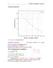
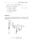
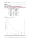
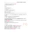
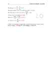
output voltage for a relative humidity of 70 % at 30 °C if R T = 50 kΩ and VDD= 2.5 V. R70 30 c =R H =9,2 kV RH 9,2 k V O= ∙ V DD= ∙ 2,5 = 0,388 V (R T + R H ) ( 50 k +9,2 k ) Hint: Check specification for Humidity Sensor of SYH-2R.pdf at http://www.rhopointcomponents.com/images/SYH-2R.pdf 2 Week 04 Homework Question 3 Given the following bridge circuit for a strain gauge, determine the value of the strain gauge resistance {RS}. Let: VIN = 5V R3 = 200 Ω R2 = 50 Ω R1 = 100 Ω a) Under no strain (VOUT = 0 V) R2 ∙ R3 RS= =100 Ω R1 b) When VOUT = 0,5 V {under strain}. 100 200 0,1= − 150 200+ RS 200 200 0,56= =¿> RS= −200=¿> RS=157 Ω 200+ RS 0,56 RS ≈157 Ω

Mikrokontrollerid ja robootika
Midterm Exam solutions and answers in Microcontroller and practical robotics
10
pdf

Midterm Exam solutions and answers in Microcontroller and practical robotics

binary and then using the twos complement method. Show all your calculations 5810=001110102 4210=001010102 Converse to twos complement 4210=001010102=110101012+1=110101102 Then 58+(42) 001110102 +110101102 = 000100002 =1610 Question 3 Given the following bridge circuit for a strain gauge, determine the value of the strain gauge resistance {RS}. Let: VIN = 5V R3 = 100 Ω R2 = 50 Ω R1 = 100 Ω 2 Midterm Exam - Solutions a) Under no strain (VOUT = 0 V) b) When VOUT = 0,5 V {under strain}. Solution: a) Under no strain:  R1 R3   R1R4  R2 R3  VOUT     IN  V   VIN  1 R  R 2 R3  R4  1 ( R  R2 )( R3  R4 

Mikrokontrollerid ja praktiline robootika
Book Analog Interfacing to Embedded Microprocessors
568
pdf

Book Analog Interfacing to Embedded Microprocessors

Analog Interfacing to Embedded Microprocessors Real World Design Analog Interfacing to Embedded Microprocessors Real World Design Stuart Ball Boston Oxford Auckland Johannesburg Melbourne New Delhi Newnes is an imprint of Butterworth–Heinemann. Copyright © 2001 by Butterworth–Heinemann A member of the Reed Elsevier group All rights reserved. No part of this publication may be reproduced, stored in a retrieval system, or transmitted in any form or by any means, electronic, mechanical, photocopying, recording, or otherwise, without the prior written permission of the publisher. Recognizing the importance of preserving what has been written, Butterworth–Heinemann prints its books on acid-free paper whenever possible. Library of Congress Cataloging-in-Publication Data Ball, Stuart R., 1956– Analog interfacing to embedded microprocessors : real world design / Stuart Ball. p. cm. ISBN 0-7506-7339-7 (pbk. : alk. paper) 1. Embedded computer

Mehhatroonika
W11 Homework Solutions
8
pdf

W11 Homework Solutions

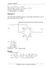
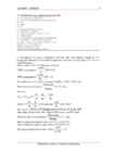
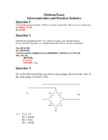
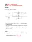
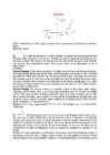
Read Chapter_6_Analog_Outputs.pdf and Chapter_8_EMI_ElectroMagnetic_Interference.pdf Question 1 Given the below open sensor detection: a. Derive equations for both outputs VO and Vsense as a function of VR, R1, Rth, RH, RL and RF. b. What value will appear on each output if the thermistor fails (becomes an open circuit)? c. How can the above schem be modified to implement temperature reading with open sensor detection using only one ADC and one digital input pin of the microcontroller? Solution: a. Derive equations for both outputs as a function of VR, R1, Rth, RH, RL and RF.  Rth  Writing the equation for V1 : V1  VSense   VR  th R  R1 V0  V2 VR  V2 V2 Writing the equation for V2 :   RF RH

Mikrokontrollerid ja praktiline robootika
CPM1A Programmable Controllers Operation Manual 1784470
402
pdf

CPM1A Programmable Controllers Operation Manual 1784470

Cat. No. W317-E1-11 SYSMAC CPM1A Programmable Controllers OPERATION MANUAL CPM1A Programmable Controllers Operation Manual Revised October 2007 iv Notice: OMRON products are manufactured for use according to proper procedures by a qualified operator and only for the purposes described in this manual. The following conventions are used to indicate and classify precautions in this manual. Always heed the information provided with them. Failure to heed precautions can result in injury to people or dam- age to property. ! DANGER Indicates an imminently hazardous situation which, if not avoided, will result in death or serious injury. Additionally, there may be severe property damage. ! WARNING Indicates a potentially hazardous situation which, if not avoided, could result in death or serious inju

Automatiseerimistehnika
Piletid vastustega
13
docx

Piletid vastustega

For this to occur, the Q point is located at cutoff on both the dc and ac load lines. Transistors are, because transistorized base bias is usually designed to operate in switching circuits by having either low output voltage or high output voltage.5)on circuits.6)Inverters output voltage is in the opposite polarity to the input voltage.Multiplexer is a multiple switch that steers one of the input signals to the output.Comparator:perfect solution for comparing one voltage with another to see which is larger.Latch:because the collector of T1 drives the base of T2 and vice versa,it is a positive feedback.Achange in current at any point of the loop is amplified and returned to the starting point with the same phase. 7)Advantages of swithces:Extremely low power consumption and lower heat production.Physically small.They can provide large load currents at low voltages although they produce more electrical and audible noise

Elektroonika jõupooljuht tehnika
Elektroonika Alused
46
doc

Elektroonika Alused

[vaata | 1. Füüsikaliste suuruste mõisted, definitsioonid ja ühikud muuda] Voolu töö ja võimsus. Joule-Lenzi seadus. Potentsiaal ja pinge. Elektriväli, suund ja tugevus. Voolu tugevus ja tihedus. Takistus, selle sõltuvus juhi mõõtmetest. Eritakistus. Laeng ja mahtuvus. Induktiivsus. Vooliuallika elektromotoorjõud, lühisvool ja sisetakistus. Voolu töö ja võimsus. Voolu töö on võrdeline voolutugevusega I, pingega U juhi otstel ja ajaga t. [ J ] Võimsus on ajaühikus tehtud töö. [ W ] A p= t Joule-Lenzi seadus. Joule-Lenzi seadus : elektrivoolu toimel juhis eralduv soojushulk Q on võrdeline voolutugevuse I ruuduga, juhi takistusega R ja voolu kestusega t ning kus voolu töö on võrdelin

Elektroonika alused
Liha töötlemine
1168
pdf

Liha töötlemine

Handbook of Meat Processing Handbook of Meat Processing Fidel Toldrá EDITOR A John Wiley & Sons, Inc., Publication Edition first published 2010 © 2010 Blackwell Publishing Blackwell Publishing was acquired by John Wiley & Sons in February 2007. Blackwell’s publishing program has been merged with Wiley’s global Scientific, Technical, and Medical business to form Wiley-Blackwell. Editorial Office 2121 State Avenue, Ames, Iowa 50014-8300, USA For details of our global editorial offices, for customer services, and for information about how to apply for permission to reuse the copyright material in this book, please see our website at www.wiley.com/ wiley-blackwell. Authorization to photocopy items for internal or personal use, or the internal or personal use of specific clients, is granted by Blackwell Publishing, provided that the base fee is paid directly to the Copyright Clearance Center, 222 Rosewood Drive, Danvers, MA 01923. F

Inglise keel


Meedia

Kommentaarid (0)

Kommentaarid sellele materjalile puuduvad. Ole esimene ja kommenteeri


Sellel veebilehel kasutatakse küpsiseid. Kasutamist jätkates nõustute küpsiste ja veebilehe üldtingimustega Nõustun