Vajad kellegagi rääkida?
Küsi julgelt abi LasteAbi
Logi sisse

Subaru Legacy 1998 Kere (0)

5 VÄGA HEA
Punktid

5-1 [ S100 ]
SPECIFICATIONS AND  SERVICE  DATA
1. Supplemental Restraint System “ Airbag
1. Supplemental Restraint
2.  Body   Datum   Points
System “Airbag”
Various master repair locations are  established  as
Airbag system  wiring  harness is routed on and
datum points used during body repairs. In  addition ,
along body panels.
guide  holes, locators and indents are  provided  to
facilitate panel replacement and achieve alignment
CAUTION:
¼
accuracy.
All Airbag system wiring harness and con-
nectors are colored yellow. Do not use electri-
NOTE :
cal test equipment on  these  circuits.
Left  and right datum points are all symmetrical to
¼ Be careful not to damage Airbag system wir-
each  other .
ing harness when repairing the body panel.
A:  ENGINE  COMPARTMENT AND  ROOM
B5M0187B
(0)
Cowl panel  weather  attaching
(7)
Side  frame  of  front  side frame 12
(27) Front  fender  attaching hole at
hole 6 mm (0.24 in) dia.
mm (0.47 in) dia.
front pillar  lower  portion M6
(1)
Hood hinge front attaching hole
(8)
Headlight attaching hole at radia-
(28) Hinge  middle  hole at front pillar
M8
tor side panel 6.2 × 9 mm (0.244
center  10 mm (0.39 in) dia.
(2)
Strut  mount  attaching hole (Front
× 0.35 in) dia.
(29) Front fender attaching hole at
center) 9.5 mm (0.374 in) dia.
(9)
Radiator  panel side (LWR)
front pillar center portion M6
(3)
Front fender attaching hole (Tip)
gauge hole 23 mm (0.91 in) dia.
(30) Retainer attaching  square  hole
M6
(23)  Rear  strut mount attaching hole
at front pillar 7 × 7 mm (0.28 ×
(4)
Rear  upper  surface of front side
(Side) 10 mm (0.39 in) dia.
0.28 in)
frame 12 mm (0.47 in) dia.
(24) Rear strut mount attaching hole
(31) Retainer attaching hole at center
(5)
Middle upper surface of front
(Center) 12 mm (0.47 in) (0.244
pillar (Front) 3.5 mm (0.138 in)
side frame 20 mm (0.79 in) dia.
× 0.35 in) dia.
dia.
(6)
Front side frame front upper sur-
(25) Radiator panel (UPR) middle
(32) Retainer attaching hole at center
face  14 × 16 mm (0.55 × 0.63 in)
hole 6 mm (0.24 in) dia.
pillar (Rear) 3.5 mm (0.138 in)
dia. oblong hole
(26) Front fender attaching hole at
dia.
radiator panel side M6
2
SPECIFICATIONS AND SERVICE DATA
[ S2B1 ] 5-1
2. Body Datum Points
(33) Lower side of rear  door  hinge
(41)  Stud  bolt lower locating  notch
(55)  Trim  upper attaching hole at 6
M8
(48) Front center of rear floor pan 8
light  8 mm (0.31 in) dia.
(34) Center pillar (LWR) gauge hole
mm (0.31 in) dia.
(56) Trim lower attaching hole at 6
27 mm (1.06 in) dia.
(51) Front upper pillar (Inner) 7 mm
light 8 mm (0.31 in) dia.
(35) Rear quarter  outer  corner  patch
(0.28 in) dia.
(58) Rear floor,  near  floor strut 15 ×
attaching hole 5.2 mm (0.205 in)
(52) Front seat  belt  adjust plate
20 mm (0.59 × 0.79 in) dia.
dia.
attaching hole 12 mm (0.47 in)
oblong hole
(39) Front  rail  center notch
dia.
(40) Front glass upper locating notch
(53) Rear door hinge middle hole 10
RH: 6.5 mm (0.256 in) dia., LH:
mm (0.39 in) dia.
6.5 × 10 mm (0.256 × 0.39 in)
(54) Rear floor, near door 8 mm (0.31
dia. oblong hole
in) dia.
B:  LUGGAGE  COMPARTMENT AND ROOM
1. SEDAN
B5M0188B
(36) 6 light upper retainer attaching
(45) Rear panel drain locater concave
(67) Rear bumper side attaching hole
square hole 7 × 7 mm (0.28 ×
part
6 mm (0.24 in) dia.
0.28 in)
(46) Front panel gauge hole 10 mm
(68) Rear combination light mounting
(42) Rear rail center notch
(0.39 in) dia.
hole 8 mm (0.31 in) dia.
(43) Rear glass upper locating hole
(47) Tunnel center M8
(69) Rear bumper beam attaching
RH: 6.5 mm (0.256 in) dia., LH:
(59) Rear bumper attaching hole 45
hole RH: 8 mm (0.31 in) dia.,
6.5 × 10 mm (0.256 × 0.39 in)
mm (1.77 in) dia.
LH: 8 × 12 mm (0.31× 0.47 in)
dia. oblong hole
(65) Rear wiper attaching hole M6
dia. oblong hole
(44) Rear glass molding attaching
(66) Trim attaching hole at rear skirt
square hole 8 × 8 mm (0.31 ×
(UPR) 7 mm (0.28 in) dia.
0.31 in)
3
5-1 [ S2B2 ]
SPECIFICATIONS AND SERVICE DATA
2. Body Datum Points
2.  WAGON
B5M0189B
(37) D pillar  cover  attaching hole 12 ×
(57) Retainer attaching square hole
(64) Buffer attaching hole (UPR) M6
8 mm (0.47 × 0.31 in) dia.
at C pillar (UPR) 7 × 7 mm (0.28
(70) Rear quarter end (LWR) gauge
(38) Shoulder  mole  attaching hole 8
× 0.28 in)
hole 20 mm (0.79 in) dia.
mm (0.31 in) dia.
(60) Trim attaching hole at rear skirt
(71) Rear combination light mounting
(49) Front pillar (LWR) gauge hole 10
(UPR) 15 mm (0.59 in) dia.
hole 7 mm (0.28 in) dia.
mm (0.39 in) dia. (On  both
(61) Rear bumper side attaching hole
Sedan and Wagon)
6 mm (0.24 in) dia.
(50) Front pillar (UPR) gauge hole 16
(62) Rear seat belt bolt hole 13 mm
mm (0.63 in) dia. (On both
(0.51 in) dia.
Sedan and Wagon)
(63) Rear rail locator concave part
4
SPECIFICATIONS AND SERVICE DATA
[ S2D0 ] 5-1
2. Body Datum Points
C: UNDERBODY
B5M0190B
(10) Radiator panel (LWR) frame
(15) Front side frame rear lower cen-
(20) Rear crossmember attaching
gauge hole 10 mm (0.39 in) dia.
ter surface 20 mm (0.79 in) dia.
hole M12
(11) Front side frame front lower sur-
(16) Transmission mount attaching
(21) Rear frame center hole 7 mm
face 20 mm (0.79 in) dia.
hole M10
(0.28 in) dia.
(12) Front side frame center lower
(17) Front side frame rear lower sur-
(22) Rear frame rear concave part 15
surface 20 mm (0.79 in) dia.
face 15 mm (0.59 in) dia.
mm (0.59 in) dia.
(13) Front  suspension  attaching hole
(18) Rear frame front M12
M14
(19) Rear frame front hole 25 mm
(14) Suspension attaching  bracket
(0.98 in) dia.
M14
D: DATUM POINT  LOCATION
B5M0191B
B5M0192B
5
5-1 [S2D0]
SPECIFICATIONS AND SERVICE DATA
2. Body Datum Points
B5M0193B
B5M0194B
B5M0195B
B5M0196B
B5M0197B
B5M0198B
B5M0199B
B5M0200B
6
SPECIFICATIONS AND SERVICE DATA
[S2D0] 5-1
2. Body Datum Points
B5M0201B
B5M0202B
B5M0204B
B5M0203B
B5M0206B
B5M0205B
B5M0207B
B5M0208B
7
5-1 [S2D0]
SPECIFICATIONS AND SERVICE DATA
2. Body Datum Points
B5M0210B
B5M0209B
B5M0211B
B5M0212B
B5M0213B
B5M0214B
B5M0215B
B5M0216B
8
SPECIFICATIONS AND SERVICE DATA
[S2D0] 5-1
2. Body Datum Points
B5M0217B
B5M0218B
B5M0219B
B5M0220B
B5M0222B
B5M0221B
B5M0223B
B5M0224B
9
5-1 [S2D0]
SPECIFICATIONS AND SERVICE DATA
2. Body Datum Points
B5M0225B
B5M0226B
B5M0227B
B5M0228B
B5M0229B
B5M0230B
B5M0231B
B5M0232B
10
SPECIFICATIONS AND SERVICE DATA
[S2D0] 5-1
2. Body Datum Points
B5M0233B
B5M0234B
B5M0235B
B5M0236B
B5M0237B
B5M0238B
11
5-1 [S2D0]
SPECIFICATIONS AND SERVICE DATA
2. Body Datum Points
B5M0239B
B5M0240B
B5M0241B
B5M0242B
B5M0244B
B5M0243B
B5M0245B
B5M0246B
12
SPECIFICATIONS AND SERVICE DATA
[ S300 ] 5-1
3. Datum Dimensions
B5M0248B
B5M0247B
B5M0249B
3. Datum Dimensions
NOTE:
¼ A suffix  character  “R” or “L” refers to the right or
Use a  tram   tracking  gauge to measure all dimen-
the left.
sions. If a measuring tape is used, be extremely
¼ All dimensions refer to the  distance   between  the
careful because it tends to deflect or  twist , which
centers of holes measured in a straight line.
results in a  false  reading.
¼ Each dimension indicates a projected dimension
between hole centers.
G5M0122
13
Vasakule Paremale
Subaru Legacy 1998 Kere #1 Subaru Legacy 1998 Kere #2 Subaru Legacy 1998 Kere #3 Subaru Legacy 1998 Kere #4 Subaru Legacy 1998 Kere #5 Subaru Legacy 1998 Kere #6 Subaru Legacy 1998 Kere #7 Subaru Legacy 1998 Kere #8 Subaru Legacy 1998 Kere #9 Subaru Legacy 1998 Kere #10 Subaru Legacy 1998 Kere #11 Subaru Legacy 1998 Kere #12
Punktid 50 punkti Autor soovib selle materjali allalaadimise eest saada 50 punkti.
Leheküljed ~ 12 lehte Lehekülgede arv dokumendis
Aeg2012-12-22 Kuupäev, millal dokument üles laeti
Allalaadimisi 5 laadimist Kokku alla laetud
Kommentaarid 0 arvamust Teiste kasutajate poolt lisatud kommentaarid
Autor 220v Õppematerjali autor

Sarnased õppematerjalid

Ford escorti käsiraamat
256
pdf

Ford escorti käsiraamat

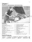
1·1 Chapter 1 Routine maintenance and servicing 1 Contents Air cleaner element renewal . . . . . . . . . . . . . . . . . . . . . . . . . . . . . . .34 Fuel filter renewal - fuel injection engines . . . . . . . . . . . . . . . . . . . .36 Alternator drivebelt check . . . . . . . . . . . . . . . . . . . . . . . . . . . . . . . .20 Hinge and lock check and lubrication . . . . . . . . . . . . . . . . . . . . . . .31 Automatic transmission fluid level check . . . . . . . . . . . . . . . . . . . . .27 Idle speed and mixture adjustment . . . . .

Auto õpetus
Body and exterior vocabulary autotehnik
6
docx

Body and exterior vocabulary autotehnik

Vocabulary with definitions Body and exterior Body components, including windows and trim: · Bonnet/hood : UK (US hood) the metal cover over the part of a car where the engine is I looked under the bonnet and clouds of smoke poured out. (KAPOTT) · Bonnet/hood latch: a type of mechanical fastener that is used to join two (or more) objects or surfaces together while allowing for the regular or eventual separation of the objects or surfaces. · Bumper: a horizontal bar along the lower front and lower back part of a motor vehicle to help protect it if there is an accident. (AMORTISAATOR/PÕRKERAUD) · Unexposed bumper ­ can´t be seen · Exposed bumper ­ can be seen · Cowl screen: (KAITSEVÕRE) · A cowling: is the covering of a vehicle's engine, most often found on automobiles and aircraft. (KAPOTT) A cowling may be used: · for drag reduction · for en

Erialaline inglise keel
CPM1A Programmable Controllers Operation Manual 1784470
402
pdf

CPM1A Programmable Controllers Operation Manual 1784470

Cat. No. W317-E1-11 SYSMAC CPM1A Programmable Controllers OPERATION MANUAL CPM1A Programmable Controllers Operation Manual Revised October 2007 iv Notice: OMRON products are manufactured for use according to proper procedures by a qualified operator and only for the purposes described in this manual. The following conventions are used to indicate and classify precautions in this manual. Always heed the information provided with them. Failure to heed precautions can result in injury to people or dam- age to property. ! DANGER Indicates an imminently hazardous situation which, if not avoided, will result in death or serious injury. Additionally, there may be severe property damage. ! WARNING Indicates a potentially hazardous situation which, if not avoided, could result in death or serious inju

Automatiseerimistehnika
TOPICS FOR SPEAKING
28
doc

TOPICS FOR SPEAKING

TOPICS FOR SPEAKING CYLINDER FRAME The cylinder section of the engine consists of a number of cylinder blocks, which are tightened together with the engine frame and the bedplate by means of through- going stay bolts. Two central bores, one at the top and one halfway down inside the cylinder block, enclose the cylinder liner. The upper part of the cylinder block forms part of the cooling water space around the central part of the cylinder liner, whereas the lower part forms the scavenge air space. A central bore in the bottom of the cylinder block encloses the piston rod stuffing box. The bottom is double with a hollow space through which cooling water is circulated. On the exhaust side of the cylinder block there is a circular opening leading into the longitudinal scavenge air receiver of the engine. Furthermore, there is an inlet pipe for cooling and lubricating oil. The cylinder block is provided with cleaning and inspection covers for the cooling water and

Inglise keel
2-stroke tuners handbook tuners
171
pdf

2-stroke tuners handbook tuners

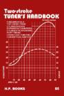
Two-Stroke TUNER’S HANDBOOK By Gordon Jennings Illustrations by the author Copyright © 1973 by Gordon Jennings Compiled for reprint © 2007 by Ken i PREFACE Many years have passed since Gordon Jennings first published this manual. Its 2007 and although there have been huge technological changes the basics are still the basics. There is a huge interest in vintage snowmobiles and their “simple” two stroke power plants of yesteryear. There is a wealth of knowledge contained in this manual. Let’s journey back to 1973 and read the book that was the two stroke bible of that era. Decades have passed since I hung around with John and Jim. John and I worked for the same corporation and I found a 500 triple Kawasaki for him at a reasonable price. He converted it into a drag bike, modified the engine completely and added mikuni carbs and tuned pipes. John borrowed Jim’s cop

Mootor
Photographic camera
18
docx

Photographic camera

2 Photographic camera & photography (SEBA)  Photographic camera is an equipment used for taking photographs (usually consisting of a lightproof box with a lens at one end and light-sensitive film at the other)  Photography is The art or practice of taking and processing photographs. 3 Context of the creation of the camera (CARLA)  The camera has been used since before Christ. The impact in society the emergence of the camera was important and shocking because it helped us capture important moments in time that can no longer be repeated and helped a lot in the field of communication. The first models of cameras were used in the years before Christ where they were used to see closely objects. After its emergence was marked a before and after in history because thanks to this artefact can capture exact moments in which a event happened. Advancing in history have improved the types of cameras, passing cameras that took several min

Inglise keel
Structural Testing Of Homebuilt Aircraft
8
pdf

Structural Testing Of Homebuilt Aircraft

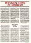
STRUCTURAL TESTING OF HOMEBUILTS Editor's Note: Alex Strojnik's Aviation articles on laminar flow in in all cases of new designs. He writings and aircraft designs have lightplane design, Alex designed also believes load testing may be in appeared in Sport Aviation many and built a very low drag powered order in a number of instances times in the past decade. A native sailplane, the S-2 (Sport Aviation, involving composite airframes. of Yugoslavia, Alex has very April 1982), which would become While there has been no history of impressive academic credentials. the first homebuilt motorglider in structural failure in composite He holds a degree in electrical engi- which International FAI Silver, Gold homebuilts that have been con- neering, a Ph. D. in aerodynamics .. and Diamond badges would be

Abimehanismid
wood properties
46
pdf

wood properties

Chapter 4 Mechanical Properties of Wood David W. Green, Jerrold E. Winandy, and David E. Kretschmann Contents he mechanical properties presented in this chapter were obtained from tests of small pieces of wood Orthotropic Nature of Wood 4–1 termed “clear” and “straight grained” because they Elastic Properties 4–2 did not contain characteristics such as knots, cross grain, Modulus of Elasticity 4–2 checks, and splits. These test pieces did have anatomical Poisson’s Ratio 4–2 characteristics such as growth rings that occurred in consis-

Ehitus materjalid ja konstruktsioonid


Meedia

Kommentaarid (0)

Kommentaarid sellele materjalile puuduvad. Ole esimene ja kommenteeri


Sellel veebilehel kasutatakse küpsiseid. Kasutamist jätkates nõustute küpsiste ja veebilehe üldtingimustega Nõustun