Vajad kellegagi rääkida?
Küsi julgelt abi LasteAbi
Logi sisse

Tugevusõpetus I kodutöö 4 / Stength of materials I HW 4 (0)

3 KEHV
Punktid

Homework nr 4 in STRENGTH of MATERIALS I (MHE0011)
Variant
Title
A
B
Strength Analysis of a Beam
8
9
Student
Student Code
Delivery Date
Teacher
18.12. 2017
Priit Põdra
Hot-rolled INP section , manufactured of steel S235 must be used for a beam. The beam will be loaded by the concentrated load F and line distributed load p.
Beam dimensions obey the relationship :
b = a/2.
The value of concentrated load is F = 10 kN and the line distributed load is uniform with the intensity: p = F/b.
The value of design factor is: [S] = 4.
The beam load case is to be chosen according to the student code last digit A. The dimensions are to be chosen according to the last but one digit of the student code B.
Required milestones:
  • Compose a scaled structural model of the beam (according to particular A and B);
  • Calculate the supports’ reactions;
  • Compose the scaled diagrams of bending moment M and shear force Q;
  • Determine the beam’ critical sections (or critical section), compose the strength condition for bending and determine the appropriate INP section with minimum material usage ;
  • Compose a scaled sketch of the chosen INP section with diagrams of normal stress and shear stress , acting at the critical section(s);
  • Calculate the values of safety factor for both bending and shear and check the adequate strength of the beam;
  • Formulate the answer .
    Beam load case according to the last digit of the student code A
    1
    2
    3
    4
    5
    6
    7
    8
    9
    0
    Beam dimensions according to the last but one digit of the student code B
    1
    2
    3
    4
    5
    a = 6,0 m; c = 2,4 m
    a = 5,5 m; c = 2,5 m
    a = 5,0 m; c = 2,6 m
    a = 4,5 m; c = 2,5 m
    a = 4,0 m; c = 1,8 m
    6
    7
    8
    9
    0
    a = 3,5 m; c = 1,5 m
    a = 3,0 m; c = 1,6 m
    a = 2,5 m; c = 1,1 m
    a = 2,0 m; c = 1,1 m
    a = 1,5 m; c = 0,7 m

    Table of Contents


    Table of Contents 2
    1.Problem Statement 3
    2. Solution 4
    2.1.Calculating the supports’ reactions 4
    2.2.Composing the scaled diagrams of bending moment M and shear force Q 5
    2.3.Determining the beam’ critical sections (or critical section), composing the strength condition for bending and determining the appropriate INP section with minimum material usage 6
    2.4.Composing a scaled sketch of the chosen INP section with diagrams of normal stress σ and shear stress τ, acting at the critical section(s)’ 7
    3. Final Results 12
  • Problem Statement


    Sketch of the problem
    Initial data:
    F is concentrated load
    p is line distributed load
    [S] is design factor
    [S] = 4
    F = 10 kN
    a =2000 mm
    c = 1100 mm
    b = a/2 = 2000/2 = 1000 mm
    p = F/b = 10/1 =10 kN*m-1
  • Solution


  • Calculating the supports’ reactions


    Equation of equilibrium for point A
    p = 10*1 = 10 kN
    L is length of distributed load
    Equation of equilibrium for point B
    Equation of equilibrium for F
    This means that support reactions’ values and directions are correct
  • Composing the scaled diagrams of bending moment M and shear force Q


    The diagram of shear force Q is done by step method . From that, I calculated the bending moment M:
    = FC * BC = 1,1*10 = 11 kNm
    = FB * BD = 10,5 * 0,5 = 5,25 kNm
    = FC * BC - FB * BD= 1,1*10 - 0,5 * 0.5 = 10,75 kNm
  • Determining the beam’ critical sections (or critical section), composing the strength condition for bending and determining the appropriate INP section with minimum material usage


    Critical sections:
    Section AE:
    Q = 10,5 kN
    M = 0 kNm
    Section BC:
    Q = 10 kN
    M = 11 kNm
    Minimum safe moment of resistance:
    When bending is acting about the axis y
    Uniform beam is safe enough, if its cross -section moment of resistance value is not smaller than 18,7 cm3
    Above is a part of a table of hot-rolled I-profiles.
    It shows the profile that corresponds to Wx≥[W]=18,7 cm3, is I 80.
    Maximum bending stress
    Check for adequate bending strength
    -> The profile is not strong enough
    Let’s choose I 200
    Check for adequate bending strength
    -> The profile is strong enough
  • Composing a scaled sketch of the chosen INP section with diagrams of normal stress σ and shear stress τ, acting at the critical section(s)’


    Maximum shear stress at points O1
    Q is cross-section shear force
    SO1 is statical moment of half -section about axis y
    I is cross-section axial moment of inertia
    s is cross-section width at O1
    Statical moment of half-section about axis y
    I = 2140 cm4
    Q = QB
    Steel yield strength for shear
    Check for adequate bending strength
    Safety of cross-section BC for shear is adequate
    Diagram of normal stress σ and shear stress τ of cross section BC
    Shear stress at the cross-section A
    Maximum shear stress at points O2
    Q is cross-section shear force
    SO2 is statical moment of half-section about axis y
    I is cross-section axial moment of inertia
    s is cross-section width at O2
    Statical moment of half-section about axis y
    I = 3060 cm4
    Q = QA
    Steel yield strength for shear
    Check for adequate bending strength
    Safety of cross-section A for shear is adequate
    Diagram of normal stress σ and shear stress τ of cross section A
    Because the bending moment MA = 0, then also the bending stress σ = 0
  • Final Results


    Minimum safe profile: I-profile DIN 1025-1 – I 200
    Critical points of a beam are A and B
    Evaluation table (to be filled by teacher)
    Correctness of the answer
    Explanations of methodics
    Quality of illustrations
    Symbols ’ clarifications
    Overall tidiness
    Total
  • Vasakule Paremale
    Tugevusõpetus I kodutöö 4- Stength of materials I HW 4 #1 Tugevusõpetus I kodutöö 4- Stength of materials I HW 4 #2 Tugevusõpetus I kodutöö 4- Stength of materials I HW 4 #3 Tugevusõpetus I kodutöö 4- Stength of materials I HW 4 #4 Tugevusõpetus I kodutöö 4- Stength of materials I HW 4 #5 Tugevusõpetus I kodutöö 4- Stength of materials I HW 4 #6 Tugevusõpetus I kodutöö 4- Stength of materials I HW 4 #7 Tugevusõpetus I kodutöö 4- Stength of materials I HW 4 #8 Tugevusõpetus I kodutöö 4- Stength of materials I HW 4 #9 Tugevusõpetus I kodutöö 4- Stength of materials I HW 4 #10 Tugevusõpetus I kodutöö 4- Stength of materials I HW 4 #11 Tugevusõpetus I kodutöö 4- Stength of materials I HW 4 #12
    Punktid 50 punkti Autor soovib selle materjali allalaadimise eest saada 50 punkti.
    Leheküljed ~ 12 lehte Lehekülgede arv dokumendis
    Aeg2017-12-27 Kuupäev, millal dokument üles laeti
    Allalaadimisi 84 laadimist Kokku alla laetud
    Kommentaarid 0 arvamust Teiste kasutajate poolt lisatud kommentaarid
    Autor KaKore Õppematerjali autor
    Tugevusõpetus I inglisekeelne kodutöö lahenduskäik. Variant 89. Hinne 5.

    Sarnased õppematerjalid

    Tugevusõpetus I kodutöö 1- Stength of materials I HW 1
    7
    docx

    Tugevusõpetus I kodutöö 1 / Stength of materials I HW 1

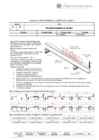
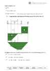
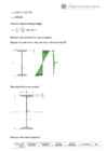
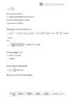
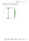
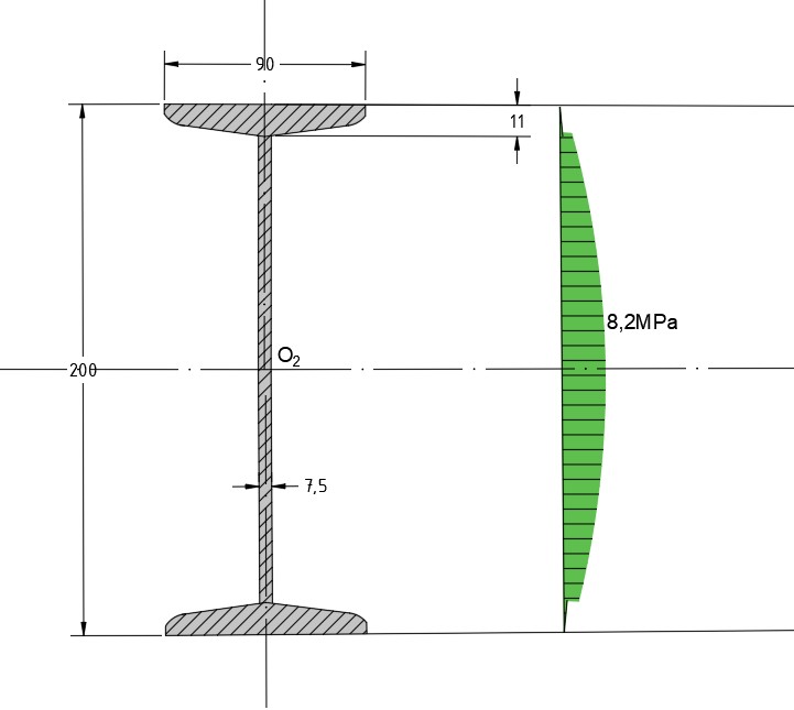
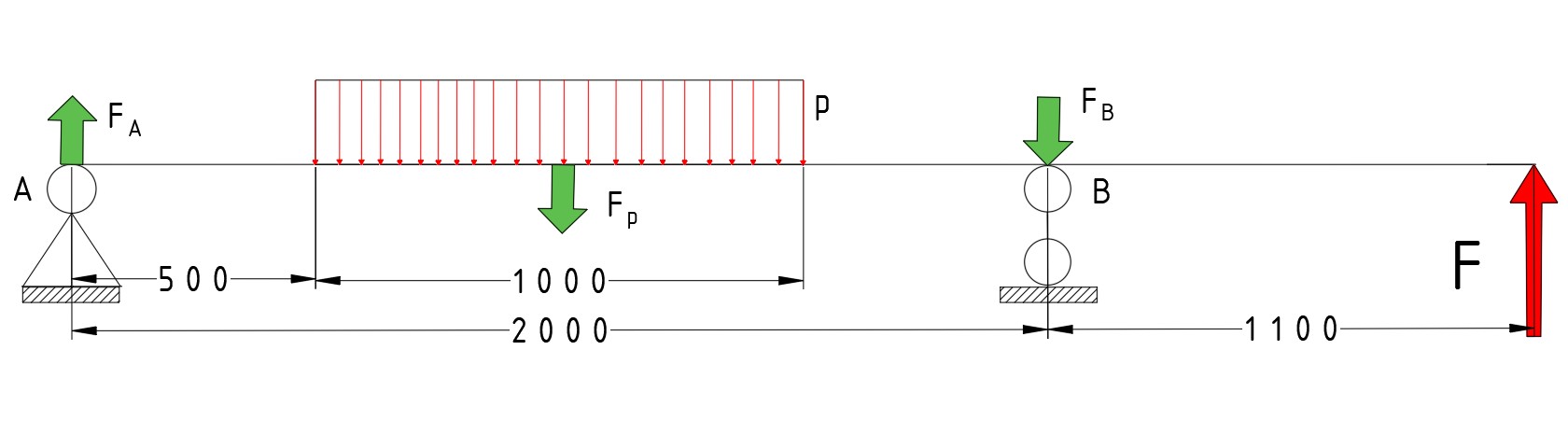
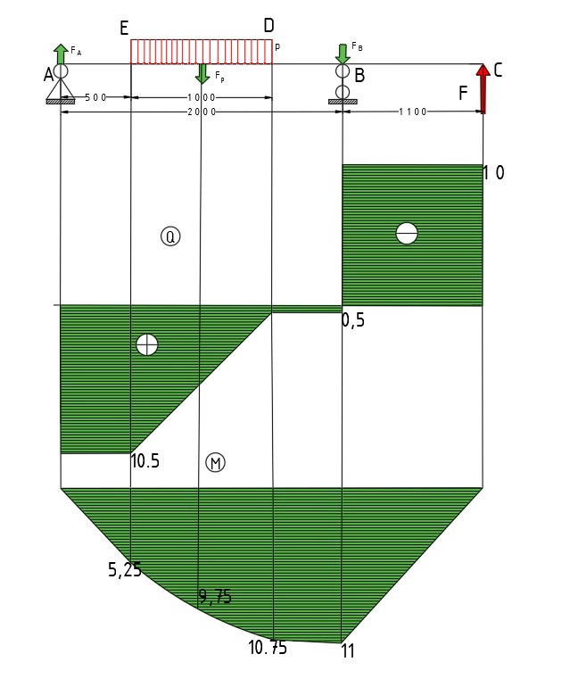
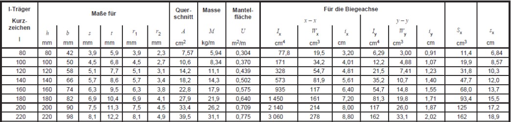
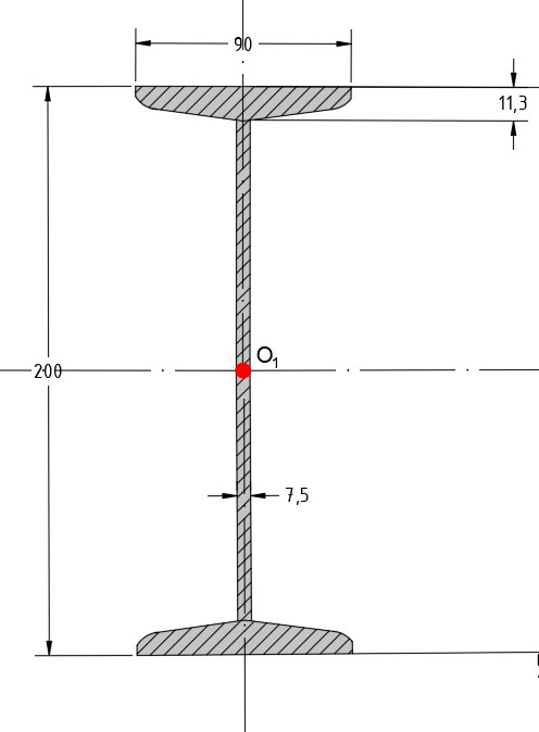
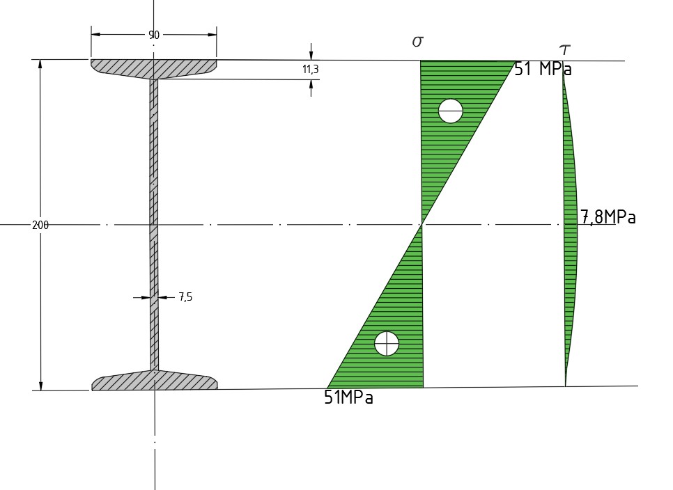
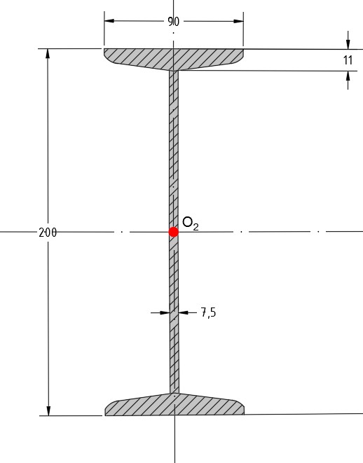
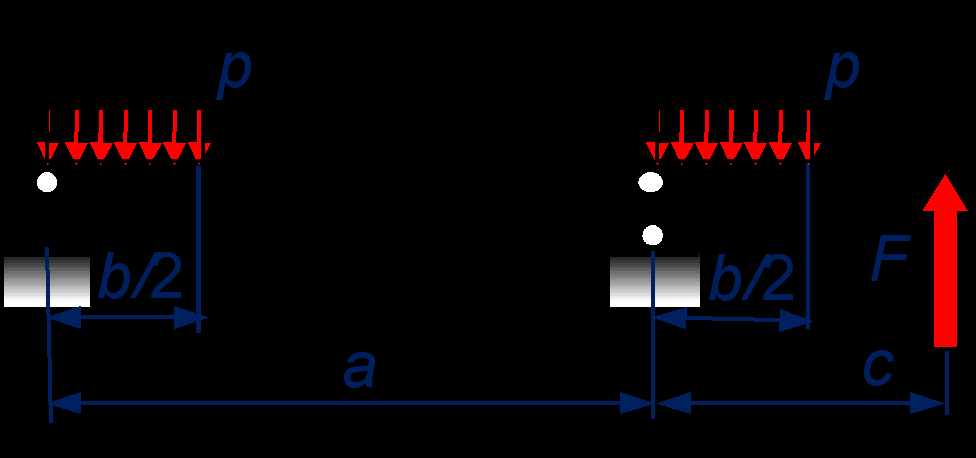
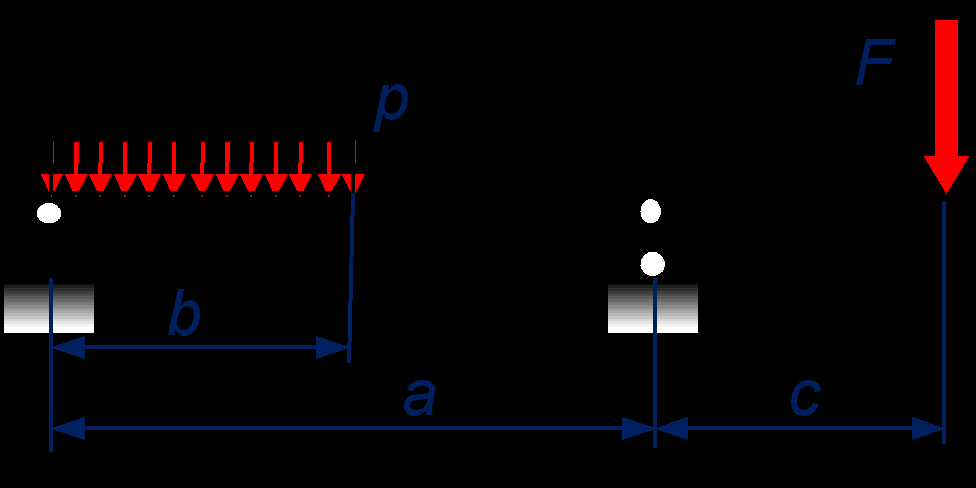
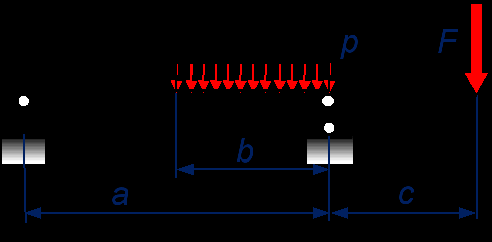
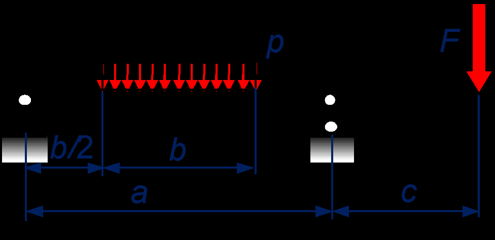
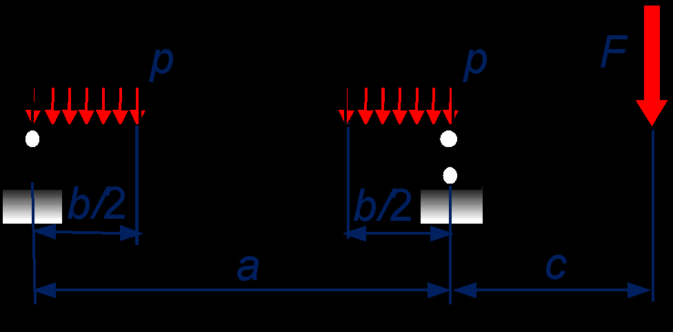
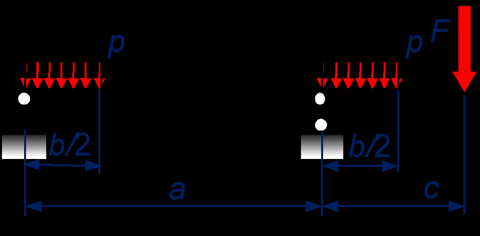
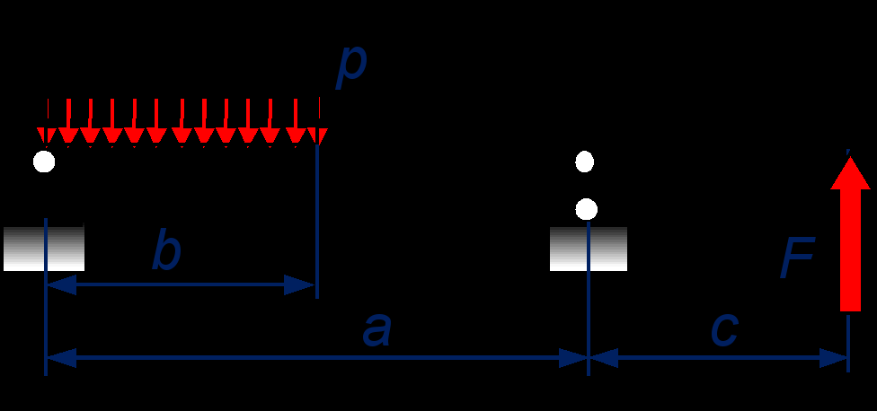
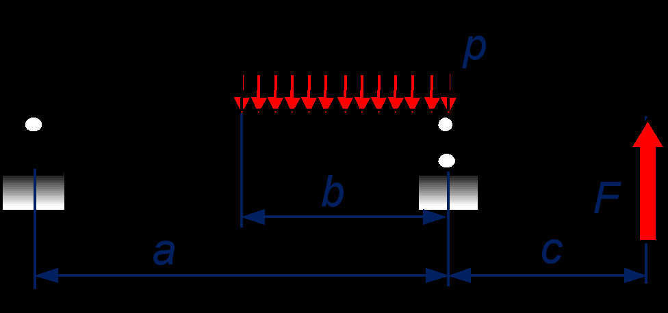
    Homework nr 1 in STRENGTH of MATERIALS I (MHE0011) Variant Title A B Strength Analysis of a Bar Structure 8 9 Student Student Code Delivery Date Teacher' Name Karina Korell 164498 MVEB 16.12.2017 Priit Põdra The structure consists of 2 members: steel wire rope 7x7 and a circular bar made of Aluminum alloy Al Mg4.5Mn0.7. The structure is loaded by the vertical force F that is acting at the joint, connecting these components. Calculate the minimum allowed diameter d of the aluminum bar and the maximum allowed value of the load F, assuming the relative position and mechanical properties of components (manufacturing tolerances, components' mass, possible stress concentration and buck

    Tugevusõpetus i
    wood properties
    46
    pdf

    wood properties

    Knots 4–27 tain; nevertheless, the properties represent the best informa- Slope of Grain 4–28 tion available. Annual Ring Orientation 4–30 Reaction Wood 4–31 Variability, or variation in properties, is common to all Juvenile Wood 4–32 materials. Because wood is a natural material and the tree is Compression Failures 4–33 subject to many constantly changing influences (such as Pitch Pockets 4–33 moisture, soil conditions, and growing space), wood proper- Bird Peck 4–33 ties vary considerably, even in clear material. This chapter

    Ehitus materjalid ja konstruktsioonid
    Structural Testing Of Homebuilt Aircraft
    8
    pdf

    Structural Testing Of Homebuilt Aircraft

    It will also contribue straight lines). Twice the stress, twice observed on a tensile specimen of a to his peace of mind. the strain. The behavior of the certified spruce (yield point around Let us start by pausing briefly to stretched aluminum alloy (20 24 -T3), 5.3 ksi, ultimate strength about 9.4 consider a peculiar mechanical prop- spruce, or 4130 steel (not shown) is, ksi), or a low carbon steel, or CrMo erty of composite materials. Figure 1 however, quite different. Take, for steel, among others. shows the relationship between the example, aluminum. As the tensile Experiments in the testing device, tensile stress the material is subjected force is applied, the specimen (for as well as our own daily experience, to, and the corresponding relative example, in the testing machine) ini- show that as long as the material is

    Abimehanismid
    ABS Piping Australian Presentation
    92
    ppt

    ABS Piping Australian Presentation

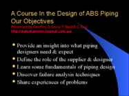
    A Course In the Design of ABS Piping Our Objectives Presented by Geoffrey D Stone FIMechE C.Eng http://waterhammer.hopout.com.au/ Provide an insight into what piping designers need & expect Define the role of the supplier & designer Learn some fundamentals of piping design Discover failure analysis techniques Share experiences of problems A Course In the Design of ABS Piping What We Shall Look at This Week ABS Material Properties Thermoplastic Pipe Design Waterhammer Analysis Typical Applications of ABS Pressure Pipe Some Anticipated Events Stages of the Design Process Representation-Drawings & Specification Calculation-Engineering & Assumptions Visualisation-Presentation of Information Validation-Testing & Commissioning Role of the ABS Pipe Supplier What the Customer Expects Avoid the following: Material Properties Accept design risk for a sale

    Inglise keel
    CPM1A Programmable Controllers Operation Manual 1784470
    402
    pdf

    CPM1A Programmable Controllers Operation Manual 1784470

    Please read and understand this manual before using the product. Please consult your OMRON representative if you have any questions or comments. Warranty and Limitations of Liability ÁÁÁÁÁÁÁÁÁÁÁÁÁÁÁÁÁÁÁÁÁÁÁÁÁÁÁÁÁÁÁÁÁ ÁÁÁÁÁÁÁÁÁÁÁÁÁÁÁÁÁÁÁÁÁÁÁÁÁÁÁÁÁÁÁÁÁ WARRANTY ÁÁÁÁÁÁÁÁÁÁÁÁÁÁÁÁÁÁÁÁÁÁÁÁÁÁÁÁÁÁÁÁÁ OMRON’s exclusive warranty is that the products are free from defects in materials and workmanship for ÁÁÁÁÁÁÁÁÁÁÁÁÁÁÁÁÁÁÁÁÁÁÁÁÁÁÁÁÁÁÁÁÁ a period of one year (or other period if specified) from date of sale by OMRON. ÁÁÁÁÁÁÁÁÁÁÁÁÁÁÁÁÁÁÁÁÁÁÁÁÁÁÁÁÁÁÁÁÁ ÁÁÁÁÁÁÁÁÁÁÁÁÁÁÁÁÁÁÁÁÁÁÁÁÁÁÁÁÁÁÁÁÁ OMRON MAKES NO WARRANTY OR REPRESENTATION, EXPRESS OR IMPLIED, REGARDING ÁÁÁÁÁÁÁÁÁÁÁÁÁÁÁÁÁÁÁÁÁÁÁÁÁÁÁÁÁÁÁÁÁ

    Automatiseerimistehnika
    How to write a Design Report
    18
    pdf

    How to write a Design Report

    A lab report describes an experiment and its conclusions and has four main parts: Introduction, Methods, Results and Discussion. The major difference between design and lab reports is that design reports do not include a methods section (other than when describing the evaluation plan.) When performing an experiment, the method that you use to obtain an answer must be presented for someone else to validate the results. For example, when testing the emissivity of a material, the difference between using a thermopile and using an energy balance will affect the results. The absence of a methods section in your design report may be disconcerting because you might have spent up to half the semester considering different concepts before choosing one, but ultimately you won’t write about that process. The audience only cares about what you came up with and not how you got there. A design report is not a history (“first we tried this

    Tootedisain
    Liha töötlemine
    1168
    pdf

    Liha töötlemine

    , Publication Edition first published 2010 © 2010 Blackwell Publishing Blackwell Publishing was acquired by John Wiley & Sons in February 2007. Blackwell’s publishing program has been merged with Wiley’s global Scientific, Technical, and Medical business to form Wiley-Blackwell. Editorial Office 2121 State Avenue, Ames, Iowa 50014-8300, USA For details of our global editorial offices, for customer services, and for information about how to apply for permission to reuse the copyright material in this book, please see our website at www.wiley.com/ wiley-blackwell. Authorization to photocopy items for internal or personal use, or the internal or personal use of specific clients, is granted by Blackwell Publishing, provided that the base fee is paid directly to the Copyright Clearance Center, 222 Rosewood Drive, Danvers, MA 01923. For those organizations that have been granted a photocopy license by CCC, a separate system of payments has been arranged. The fee codes

    Inglise keel
    Pinnakareduse standardid
    8
    pdf

    Pinnakareduse standardid

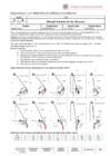
    ISO 1302: '02 Additional item (blue) is indicated if necessary. not allowed Required Manufacturing method Surface parameter and condition c ground Material removal Example a U 0.008 - 2.5/Rz3max 12.3 e d b 3 L"2RC"0.008 - 0.8/Ra75 0.2

    Materjaliõpetus


    Meedia

    Kommentaarid (0)

    Kommentaarid sellele materjalile puuduvad. Ole esimene ja kommenteeri


    Sellel veebilehel kasutatakse küpsiseid. Kasutamist jätkates nõustute küpsiste ja veebilehe üldtingimustega Nõustun