Vajad kellegagi rääkida?
Küsi julgelt abi LasteAbi
Logi sisse

Microcontroller homework 07 (0)

5 VÄGA HEA
Punktid
Microcontroller homework for week 12
  • Three different stepper motors (illustrations on page 162-163):

    The VR stepper has a soft iron rotor with teethand a wound stator . As current is applied to two opposing stator coils, the rotor is pulled into alignment with these twocoils. As the next pair of coils is energized, the rotor advances to the next position .
    The permanent magnet (PM) stepper has a rotor with alternating north and south . As the coils are energized, the rotor is pulled around . This figure shows a single coil to illustrate the concept , but a realstepper would have stator windings surrounding the rotor. The PM stepper has more torque than an equivalent VR stepper.
    The hybrid stepper essentially adds teeth to a permanent magnet motor ,resulting in better coupling of the magnetic field into the rotor and moreprecise movement. In a hybrid stepper, the rotor is split into two parts, anupper and lower . One half is the north side of the magnet andone is the south. The teeth are offset so that when the teeth of one magnetare lining up with the mating teeth on the stator, the teeth on the other arelining up with the grooves, the tops of the teethare crosshatched for clarity). Some hybrid steppers have more than one stackof magnets for more torque.
  • There are two types of stator winding methods forstepper motors: bipolar and unipolar.
    Bipolar windings use field coils with no common connections. The coils must be driven independently to reverse the direction of motor flow and rotate the motor.
    Unipolar motors use coils with centertaps. The centertap is usually connected to the positive supply , and the individual coils are grounded ( through transistors) to drive the motor.
    Each time the field is changed in a bipolar motor or a different coil isturned on in a unipolar motor, the motor shaft steps to the next rotation position. Typical step sizes for a stepper are 7.5° or 15°. A 7.5° stepper will have360/7.5 or 48 steps per revolution . The step size depends on the number of rotor and stator teeth.
  • Considering the following circuit diagrams


    The Table:
    A
    B
    C
    D
    Q1
    Q2
    Q3
    Q4
    Q5
    Q6
    Q7
    Q8
    Coil A/B
    0
    0
    0
    0
    OFF
    OFF
    OFF
    OFF
    OFF
    OFF
    OFF
    OFF
    A:OFF B:OFF
    0
    0
    0
    1
    OFF
    OFF
    OFF
    OFF
    OFF
    ON
    OFF
    ON
    A:OFF
    B:
    0
    0
    1
    0
    OFF
    OFF
    OFF
    OFF
    ON
    OFF
    ON
    OFF
    A:OFF
    B:
    0
    0
    1
    1
    OFF
    OFF
    OFF
    OFF
    ON
    ON
    ON
    ON
    A:OFF
    B:CC
    0
    1
    0
    0
    OFF
    ON
    OFF
    ON
    OFF
    OFF
    OFF
    OFF
    A:
    B:OFF
    0
    1
    0
    1
    OFF
    ON
    OFF
    ON
    OFF
    ON
    OFF
    A:
    B:
    0
    1
    1
    0
    OFF
    ON
    OFF
    ON
    ON
    OFF
    ON
    OFF
    A:
    B:
    0
    1
    1
    1
    OFF
    ON
    OFF
    ON
    ON
    ON
    ON
    ON
    A:
    B:CC
    1
    0
    0
    0
    ON
    OFF
    ON
    OFF
    OFF
    OFF
    OFF
    OFF
    A:
    B:OFF
    1
    0
    0
    1
    ON
    OFF
    ON
    OFF
    OFF
    ON
    OFF
    ON
    A:
    B:
    1
    0
    1
    0
    ON
    OFF
    ON
    OFF
    ON
    OFF
    ON
    OFF
    A:
    B:
    1
    0
    1
    1
    ON
    OFF
    ON
    OFF
    ON
    ON
    ON
    ON
    A:
    B:CC
    1
    1
    0
    0
    ON
    ON
    ON
    ON
    OFF
    OFF
    OFF
    OFF
    A:CC
    B:OFF
    1
    1
    0
    1
    ON
    ON
    ON
    ON
    OFF
    ON
    OFF
    ON
    A:CC
    B:
    1
    1
    1
    0
    ON
    ON
    ON
    ON
    ON
    OFF
    ON
    OFF
    A:CC
    B:
    1
    1
    1
    1
    ON
    ON
    ON
    ON
    ON
    ON
    ON
    ON
    A:CC
    B:CC
    The diodes , D1-D8, protect the transistors against the coil flyback voltagewhen the transistors are turned off. The motor shaft is rotated by applyingdrive voltage to each input in the proper sequence.

  • Shoot -through, also known as cross -conduction. This is the condition that occurs when the upper and lower transistors on the same side of the coil turn on at the same time. If two transistors turn on at the same time, there will be a very low impedance between the supply voltage and ground — effectively a short. This usually destroys one or both transistors. In a high-power circuit , the results can be quite dramatic, with blue sparks and pieces of transistor flying across the room . Shoot-through can be caused by bringing inputs high at the same time. It can also be caused by bringing one input high while simultaneously taking the other input low. If one of the transistors in the bridge turns off a little slower than the others turn on, the result will be momentary shoot-through.

    The usual method to avoid shoot-through is to introduce a short delay between turning off one side of the H-bridge and turning on the other. The delay must be long enough to allow both transistors to turn off before the other pair turns on.


  • a. Which pin would be used for sensing current?
    Pin 8
    b. What would be the voltage output be if a 1kΩ resistor is connected from the current sense pin to ground and the motor winding is having a current of 2.653A?
    1 V
  • Microcontroller homework 07 #1 Microcontroller homework 07 #2 Microcontroller homework 07 #3
    Punktid 50 punkti Autor soovib selle materjali allalaadimise eest saada 50 punkti.
    Leheküljed ~ 3 lehte Lehekülgede arv dokumendis
    Aeg2013-02-24 Kuupäev, millal dokument üles laeti
    Allalaadimisi 38 laadimist Kokku alla laetud
    Kommentaarid 0 arvamust Teiste kasutajate poolt lisatud kommentaarid
    Autor likoor Õppematerjali autor
    Treu Minh Vu tund, kodune töö 7

    Sarnased õppematerjalid

    Book Analog Interfacing to Embedded Microprocessors
    568
    pdf

    Book Analog Interfacing to Embedded Microprocessors

    Dynamic Range 1 Calibration 2 Bandwidth 5 Processor Throughput 6 Avoiding Excess Speed 7 Other System Considerations 8 Sample Rate and Aliasing 11 2 Digital-to-Analog Converters 13 Analog-to-Digital Converters 15 Types of ADCs 17 Sample and Hold 26 Real Parts 29 Microprocessor Interfacing 30 Serial Interfaces 36 Multichannel ADCs 41 Internal Microcontroller ADCs 41 Codecs 42 Interrupt Rate 43 Dual-Function Pins on Microcontrollers 43 Design Checklist 45 v 3 Sensors 47 Temperature Sensors 47 Optical Sensors 59 CCDs 72 Magnetic Sensors 82 Motion/Acceleration Sensors 86 Strain Gauge 90 4 Time-Based Measurements 93

    Mehhatroonika
    Piletid vastustega
    13
    docx

    Piletid vastustega

    Ticket No1 1)The characteristic is called output characteristic or volt-ampere charateristic of a Rectifier Diode. 2)Rectifier Diode. 3) A is called Anode and C is called Cathode. An Anode has positive potential and therefore collects electrons in the device. Cathode has negative potential and therefore emits electrons to anode. The symbol looks like an arrow that ponts from the anode to the cathode, and reminds that conventional current flows easily from the p side(anode) to the n side(cathode). BIASING. Forward biasing. If the current in a diode is too large, excessive heat will destroy the device. Even approaching the burnout current value without reaching it can shorten its life. Therefore manufacturer's data sheet specifies the maximum forward current, that diode can withstand. This average current IF is the rate a diode can handle up to the forward direction when used as a rectifier. Another entry of interest in the da

    Elektroonika jõupooljuht tehnika
    Elektriajamite 1-Labor
    12
    docx

    Elektriajamite 1. Labor

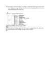
    Tallinn University of Technology Department of Electrical Engineering Report on laboratory work 1 on General Course of Electrical Drive SENSORLESS DRIVE POWER FLEX (ALLEN BRADLEY) Jüri Lina 666BMW Group M16 Variant 2 Tallinn 2014 1. Functional Diagram 2. Tables of observations Task Operation/Record Observation 1 Reverse the motor speed. How long Time to reverse was 16 does the motor reverse? seconds 2 2: Set the screen display an Output Minimal: 2.8V Voltage of the inverter. Turning the Maximal: 166V potentiometer, find accessible minimal and maximal voltages. Stop the drive. 3 3 Turn the keypad potentiometer half- Reverse ti

    Elektriajamid
    Test VIII - cumulative test
    8
    docx

    Test VIII - cumulative test

    Test VIII - cumulative test by Piigli, Mets, Parker, Kauler "Top delusion" question / answers are red. Test I The induction machines are associated with the names of Dolivo - Dobrovolsky, Tesla. The synchronous machines are associated with the name of Ferraris. The DC machines are associated with the names of Jacobi and Henry. The electromagnetic torque is born in air gap. The torque is proportional to the current in dc motor. Which equations are correct? P = sW; oomega = tuletis fii'st The angular frequency is 2*pi()*n / 60 ja 2*pi()f The motor torque is equal to TL + J * oomega tuletis aja järgi The inductor supplies the motor with flux. The leading companies in the world market of electrical drive engineering are: Mitsubishi. The energy balance is described by energy conservation law. The armature supplies the motor with current. The cheapest and the most reliable is induction motor. The torque productio

    Sissejuhatus robotitehnikasse
    Ford escorti käsiraamat
    256
    pdf

    Ford escorti käsiraamat

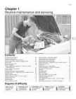
    1·1 Chapter 1 Routine maintenance and servicing 1 Contents Air cleaner element renewal . . . . . . . . . . . . . . . . . . . . . . . . . . . . . . .34 Fuel filter renewal - fuel injection engines . . . . . . . . . . . . . . . . . . . .36 Alternator drivebelt check . . . . . . . . . . . . . . . . . . . . . . . . . . . . . . . .20 Hinge and lock check and lubrication . . . . . . . . . . . . . . . . . . . . . . .31 Automatic transmission fluid level check . . . . . . . . . . . . . . . . . . . . .27 Idle speed and mixture adjustment . . . . .

    Auto õpetus
    CPM1A Programmable Controllers Operation Manual 1784470
    402
    pdf

    CPM1A Programmable Controllers Operation Manual 1784470

    Cat. No. W317-E1-11 SYSMAC CPM1A Programmable Controllers OPERATION MANUAL CPM1A Programmable Controllers Operation Manual Revised October 2007 iv Notice: OMRON products are manufactured for use according to proper procedures by a qualified operator and only for the purposes described in this manual. The following conventions are used to indicate and classify precautions in this manual. Always heed the information provided with them. Failure to heed precautions can result in injury to people or dam- age to property. ! DANGER Indicates an imminently hazardous situation which, if not avoided, will result in death or serious injury. Additionally, there may be severe property damage. ! WARNING Indicates a potentially hazardous situation which, if not avoided, could result in death or serious inju

    Automatiseerimistehnika
    Electrical drives and power electronics
    5
    docx

    Electrical drives and power electronics

    Electrical drives and power electronics TESTS · The synchronous machines are associated with the names of Ferraris · Name the scientists who first studied electrical phenomena Coulomb · The DC machines are associated with the names of Jacobi Henry · The leading companies in the world market of electrical drive engineering are Mitsubishi · · The electromagnetic torque is born in air gap · What kind of drives the majority of drive systems present low accuracy · The induction machines are associated with the names of Dolivo-Dobrovolsky Tesla · One of the first eletrical motors has been built by Jacobi · Electromagnetic efficiency is measured in tesla · Time constants are measured by ms s hours · Who is the author of the first electrical motor Henry · Which rectifier cannot be built without a transformer 3-phase midpoint · Call the benefits of 3-phase rectifiers upon the 1-phase ones output voltage · Which rectifier has more diodes 3-phase bridge · In th

    Elektriajamid
    Programmeerimiskeel
    555
    doc

    Programmeerimiskeel

    tutvu lausearvutuse keskkonnaga: http://logik.phl.univie.ac.at/~chris/gateway/formular-uk-zentral.html Millistel muutuja väärtustel on lause (Av(B&A))v(-A&(Cv(B&-C))) väär? Panna tuleb results only, 0 on väär 1 on õige Tutvu ajalooga saidis kuni II maailmasõda: http://www.maxmon.com/history.htm Loe läbi jutt ja proovi andmetega mängida: http://math.hws.edu/TMCM/java/DataReps/index.html Kahend süsteemi arvu(101101001) ->kümnend süsteemiks. Nr sisse ja bianarile punkt, ja vaatan base ten integeri kümnendarvudest annab Ecki appletis juuresoleva graafilise kujutise, teen kujundi ja vaatan base integeri mis vastab kahendsüsteemi arvule 1110001 ASCII tabelis? Nr sisse ja punkt bianari, vaatan ...teksti Kümnendsüsteemi arv 33 on kahendsüsteemis? 33 kirjutan ja Base-ten integer, vaatan bianary Loe läbi jutud Atbashi ja Caesari šifri (Caesar cipher) kohta: http://www.wikipedia.org 2 Tutvu ajalooga kuni 1970ndad: http://www.islandnet.com/~kpolsson/comphist/ 47-68 ingli

    Infotehnoloogia


    Meedia

    Kommentaarid (0)

    Kommentaarid sellele materjalile puuduvad. Ole esimene ja kommenteeri


    Sellel veebilehel kasutatakse küpsiseid. Kasutamist jätkates nõustute küpsiste ja veebilehe üldtingimustega Nõustun