TOPICS FOR SPEAKING CYLINDER FRAME The cylinder section of the engine consists of a number of cylinder blocks, which are tightened together with the engine frame and the bedplate by means of through- going stay bolts. Two central bores, one at the top and one halfway down inside the cylinder block, enclose the cylinder liner. The upper part of the cylinder block forms part of the cooling water space around the central part of the cylinder liner, whereas the lower part forms the scavenge air space. A central bore in the bottom of the cylinder block encloses the piston rod stuffing box. The bottom is double with a hollow space through which cooling water is circulated. On the exhaust side of the cylinder block there is a circular opening leading into the longitudinal scavenge air receiver of the engine. Furthermore, there is an inlet pipe for cooling and lubricating oil. The cylinder block is provided with cleaning and inspection covers for the cooling water and
the research with more money and since the first tested and viable 32 MJ railgun had been sent to the Navy, astonishing progress has been made, getting the shot count from about 10 to over a 100 and closing in on the 400 shot milestone before the rails give up due to use, which is an important part of introducing the weapon to basic military use. Unfortunately the Department of Defense has been moving away from the railgun project, leaning more towards a mixture of new and existing technologies because the electromagnetic railgun weapon system as it is now will likely never see combat in its current form. Although it has been proven that the railgun works, it hasn't reached the required 10 rounds a minute, being able to shoot about 4.8 rounds in one minute. It will probably take quite a while before research is far enough. Using a railgun as a railway for spacecrafts is also a long ways from being brought to
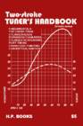
Two-Stroke TUNER’S HANDBOOK By Gordon Jennings Illustrations by the author Copyright © 1973 by Gordon Jennings Compiled for reprint © 2007 by Ken i PREFACE Many years have passed since Gordon Jennings first published this manual. Its 2007 and although there have been huge technological changes the basics are still the basics. There is a huge interest in vintage snowmobiles and their “simple” two stroke power plants of yesteryear. There is a wealth of knowledge contained in this manual. Let’s journey back to 1973 and read the book that was the two stroke bible of that era. Decades have passed since I hung around with John and Jim. John and I worked for the same corporation and I found a 500 triple Kawasaki for him at a reasonable price. He converted it into a drag bike, modified the engine completely and added mikuni carbs and tuned pipes. John borrowed Jim’s cop
SISUKORD ENERGY STORY................................................................................................................4 USES OF ENERGY............................................................................................................. 4 2.1 Uses of energy in homes...............................................................................................5 2.2 Types of energy used in homes.................................................................................... 6 2.3 Energy use in different types of homes........................................................................ 6 2.4 Commercial Energy Use...............................................................................................9 2.5 Industrial and Manufacturing Energy Use..................................................................11 2.6 Transportation Energy Use.........................................................................................12 RENE
1·1 Chapter 1 Routine maintenance and servicing 1 Contents Air cleaner element renewal . . . . . . . . . . . . . . . . . . . . . . . . . . . . . . .34 Fuel filter renewal - fuel injection engines . . . . . . . . . . . . . . . . . . . .36 Alternator drivebelt check . . . . . . . . . . . . . . . . . . . . . . . . . . . . . . . .20 Hinge and lock check and lubrication . . . . . . . . . . . . . . . . . . . . . . .31 Automatic transmission fluid level check . . . . . . . . . . . . . . . . . . . . .27 Idle speed and mixture adjustment . . . . .
Viljandi Ühendatud Kutsekeskkool. Autommaaler. Marius Lepik Autodes kasutatavad pneuma-ja hüdrosüsteemid Referaat Juhendaja: Jaanus Kaido Viljandi 2009 Compressed Air Brake System A "Compressed Air Brake System" is a different air brake used for trucks, consisting of a standard disc or drum brake arrangement using compressed air in place of hydraulic fluid. Most types of truck air brakes are drum units, though there is an increasing trend towards the use of disc brakes in this application. The compressed air brakes system works by drawing filtered air from the atmosphere, compressing it, and holding it in high-pressure reservoirs at around 120 PSI. When needed for braking, this high pressure air is routed to the operating cylinders on the brakes, which actuate the braking hardware and slow the vehic
wood-burning. Hydroelectricity was the next largest renewable source, providing 3% (15% of global electricity generation),followed by solar hot water/heating, which contributed 1.3%. Modern technologies, such as geothermal energy, wind power, solar power, and ocean energy together provided some 0.8% of final energy consumption. While there are many large-scale renewable energy projects and production, renewable technologies are also suited to small off-grid applications, sometimes in rural and remote areas, where energy is often crucial in human development.Kenya has the world's highest household solar ownership rate with roughly 30,000 small (20100 watt) solar power systems sold per year. Some renewable energy technologies are criticised for being intermittent or unsightly, yet the market is growing for many forms of renewable energy. Climate change concerns coupled with high oil
Ticket No1 1)The characteristic is called output characteristic or volt-ampere charateristic of a Rectifier Diode. 2)Rectifier Diode. 3) A is called Anode and C is called Cathode. An Anode has positive potential and therefore collects electrons in the device. Cathode has negative potential and therefore emits electrons to anode. The symbol looks like an arrow that ponts from the anode to the cathode, and reminds that conventional current flows easily from the p side(anode) to the n side(cathode). BIASING. Forward biasing. If the current in a diode is too large, excessive heat will destroy the device. Even approaching the burnout current value without reaching it can shorten its life. Therefore manufacturer's data sheet specifies the maximum forward current, that diode can withstand. This average current IF is the rate a diode can handle up to the forward direction when used as a rectifier. Another entry of interest in the da


Kõik kommentaarid