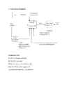
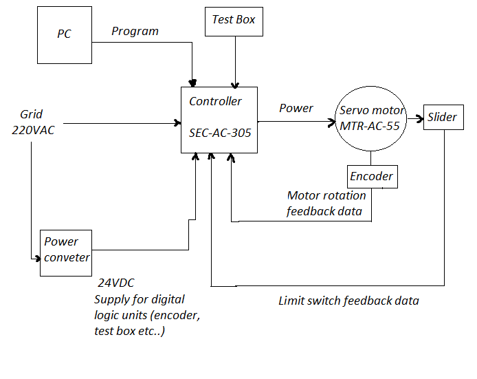
Tallinn University of Technology Department of Electrical Engineering Report on laboratory work 2 on General Course of Electrical Drive STEP DRIVE (FESTO) Jüri Lina 666BMW Group M16 Variant 2 Tallinn 2014 1. Functional Diagram 2. Program texts Program parts concenring the tasks of my variant are marked in bold, with an explanation of their meaning marked with // after them. Program 2: Velocity Profiles N000 G01 X180.13 FX20 N001 G01 X45.03 FX20 N002 G01 X180.13 FX50 // N002- Record number, G01- Move to position at specified speed, X180.13 - position parameter for X axis, FX50 -speed parameter for X axis. N003 G01 X45.03 FX50 N004 G01 X180.13 FX70 N005 G01 X45.03 FX70 N006 G01 X180.13 FX0 N007 G01 X45.03
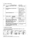
Tallinn University of Technology Department of Electrical Engineering Report on laboratory work 1 on General Course of Electrical Drive SENSORLESS DRIVE POWER FLEX (ALLEN BRADLEY) Jüri Lina 666BMW Group M16 Variant 2 Tallinn 2014 1. Functional Diagram 2. Tables of observations Task Operation/Record Observation 1 Reverse the motor speed. How long Time to reverse was 16 does the motor reverse? seconds 2 2: Set the screen display an Output Minimal: 2.8V Voltage of the inverter. Turning the Maximal: 166V potentiometer, find accessible minimal and maximal voltages. Stop the drive. 3 3 Turn the keypad potentiometer half- Reverse ti
Analog Interfacing to Embedded Microprocessors Real World Design Analog Interfacing to Embedded Microprocessors Real World Design Stuart Ball Boston Oxford Auckland Johannesburg Melbourne New Delhi Newnes is an imprint of Butterworth–Heinemann. Copyright © 2001 by Butterworth–Heinemann A member of the Reed Elsevier group All rights reserved. No part of this publication may be reproduced, stored in a retrieval system, or transmitted in any form or by any means, electronic, mechanical, photocopying, recording, or otherwise, without the prior written permission of the publisher. Recognizing the importance of preserving what has been written, Butterworth–Heinemann prints its books on acid-free paper whenever possible. Library of Congress Cataloging-in-Publication Data Ball, Stuart R., 1956– Analog interfacing to embedded microprocessors : real world design / Stuart Ball. p. cm. ISBN 0-7506-7339-7 (pbk. : alk. paper) 1. Embedded computer
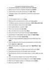
Test VIII - cumulative test by Piigli, Mets, Parker, Kauler "Top delusion" question / answers are red. Test I The induction machines are associated with the names of Dolivo - Dobrovolsky, Tesla. The synchronous machines are associated with the name of Ferraris. The DC machines are associated with the names of Jacobi and Henry. The electromagnetic torque is born in air gap. The torque is proportional to the current in dc motor. Which equations are correct? P = sW; oomega = tuletis fii'st The angular frequency is 2*pi()*n / 60 ja 2*pi()f The motor torque is equal to TL + J * oomega tuletis aja järgi The inductor supplies the motor with flux. The leading companies in the world market of electrical drive engineering are: Mitsubishi. The energy balance is described by energy conservation law. The armature supplies the motor with current. The cheapest and the most reliable is induction motor. The torque productio
Electrical drives and power electronics TESTS · The synchronous machines are associated with the names of Ferraris · Name the scientists who first studied electrical phenomena Coulomb · The DC machines are associated with the names of Jacobi Henry · The leading companies in the world market of electrical drive engineering are Mitsubishi · · The electromagnetic torque is born in air gap · What kind of drives the majority of drive systems present low accuracy · The induction machines are associated with the names of Dolivo-Dobrovolsky Tesla · One of the first eletrical motors has been built by Jacobi · Electromagnetic efficiency is measured in tesla · Time constants are measured by ms s hours · Who is the author of the first electrical motor Henry · Which rectifier cannot be built without a transformer 3-phase midpoint · Call the benefits of 3-phase rectifiers upon the 1-phase ones output voltage · Which rectifier has more diodes 3-phase bridge · In th
1·1 Chapter 1 Routine maintenance and servicing 1 Contents Air cleaner element renewal . . . . . . . . . . . . . . . . . . . . . . . . . . . . . . .34 Fuel filter renewal - fuel injection engines . . . . . . . . . . . . . . . . . . . .36 Alternator drivebelt check . . . . . . . . . . . . . . . . . . . . . . . . . . . . . . . .20 Hinge and lock check and lubrication . . . . . . . . . . . . . . . . . . . . . . .31 Automatic transmission fluid level check . . . . . . . . . . . . . . . . . . . . .27 Idle speed and mixture adjustment . . . . .
[email protected] 06 Aug 2018 FITNESS IN SOCCER THE SCIENCE AND PRACTICAL APPLICATION Jan Van Winckel, Werner Helsen, Kenny McMillan, David Tenney, Jean-Pierre Meert, Paul Bradley [email protected] 06 Aug 2018 Isbn-number : 9789082132304 Publisher: Moveo Ergo Sum / Klein-Gelmen Proofreading: Jim Newall Quill Content |Writing, Editing and Web site services http://www.quillsites.co.uk Photos: Jean Leemans and Etienne Claessens Cover and lay-out: Dots & Bits © 2014 Jan Van Winckel Printed and bound at Manipal Technologies Ltd., India All rights reserved. No pa
Cat. No. W317-E1-11 SYSMAC CPM1A Programmable Controllers OPERATION MANUAL CPM1A Programmable Controllers Operation Manual Revised October 2007 iv Notice: OMRON products are manufactured for use according to proper procedures by a qualified operator and only for the purposes described in this manual. The following conventions are used to indicate and classify precautions in this manual. Always heed the information provided with them. Failure to heed precautions can result in injury to people or dam- age to property. ! DANGER Indicates an imminently hazardous situation which, if not avoided, will result in death or serious injury. Additionally, there may be severe property damage. ! WARNING Indicates a potentially hazardous situation which, if not avoided, could result in death or serious inju


Kõik kommentaarid