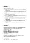
Question 1 Define the following ADC terms: 1. SNR – (Signal to Noise Ratio) SNR is a calculated value that represents the ratio of RMS signal to RMS noise. 2. SINAD - (signal-to-noise-and-distortion ratio) Ratio of the RMS signal amplitude to the mean value of the root-sum-square (RSS) 3. ENOB – (effective number of bits) The effective number-of-bits and relates to SINAD 4. THD - (total harmonic distortion) Ratio of the rms value of the fundamental signal to the mean value of the RSS of its harmonics. 5. SFDR - (spurious free dynamic range) Ratio of the RMS value of the signal to the RMS value of the worst spurious signal. 6. Channels - related to the inputs of the ADC can either be multiplexed or individually selected. 7. Linearity - relates to how a ADC follows a linear function. All ADCs are to a certain extend nonlinearity. 8. Operating temperature - measurement, which i
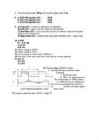
Week 4 homework. Question 1: 1. SNR – Ratio of root mean square signal to root mean square. 2. SINAD – Ratio of the RMS signal amplitude to the mean of value of the root sum square. 3. ENOB – The effective number of bits and relates to SINAD. 4. THD – Ratio of the rms value of the fundamental signal to the mean value of RSS of its harmonics. 5. SFDR – Ratio of the RMS value of the signal to the RMS value of the worst spurious signal. 6. Channels – multiple analog signal inputs to the ADC that can be individually selected or selected through a multiplexor. 7. Linearity – Describes how an ADC conveter follows a linear function. 8. Operating temperature – A temperature at which the ADC functions optimally, usually given by the manufacturer. 9. Power dissipation – The proportion of power dissipated (through heat) when the ADC is working. Question 2: An 8 bit ADC has a reference voltage of 5V. What is the digital output code word for an input of 1.2V? 0011
Question 1 (in wiki and in terminologies) 1. SNR is a calculated value that represents the ratio of root- mean-square (rms ) signal to rms noise. 2. SINAD stands for Signal-to-noise and distortion ratio. It is a measure of the quality of a signal from a communications device, often defined as: where is the average power of the signal, noise and distortion components. SINAD is usually expressed in dB. For examples to calculate the ratio of 1 kW (one kilowatt, or 1000 watts) to 1 W in decibels, use the formula 3. ENOB is the effective number-of-bits related to SINAD and the quality of a digitized signal. The 6.02 term in the divisor converts decibels (a log10) to bits (a log2) The 1.76 term comes from quantization error in an ideal ADC 4. THD - Total harmonic distortion is the ratio of the root-mean-square (rms) value of the fundamental signal to the mean value
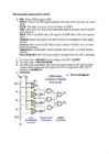
Dynamic Range 1 Calibration 2 Bandwidth 5 Processor Throughput 6 Avoiding Excess Speed 7 Other System Considerations 8 Sample Rate and Aliasing 11 2 Digital-to-Analog Converters 13 Analog-to-Digital Converters 15 Types of ADCs 17 Sample and Hold 26 Real Parts 29 Microprocessor Interfacing 30 Serial Interfaces 36 Multichannel ADCs 41 Internal Microcontroller ADCs 41 Codecs 42 Interrupt Rate 43 Dual-Function Pins on Microcontrollers 43 Design Checklist 45 v 3 Sensors 47 Temperature Sensors 47 Optical Sensors 59 CCDs 72 Magnetic Sensors 82 Motion/Acceleration Sensors 86 Strain Gauge 90 4 Time-Based Measurements 93
Cat. No. W317-E1-11 SYSMAC CPM1A Programmable Controllers OPERATION MANUAL CPM1A Programmable Controllers Operation Manual Revised October 2007 iv Notice: OMRON products are manufactured for use according to proper procedures by a qualified operator and only for the purposes described in this manual. The following conventions are used to indicate and classify precautions in this manual. Always heed the information provided with them. Failure to heed precautions can result in injury to people or dam- age to property. ! DANGER Indicates an imminently hazardous situation which, if not avoided, will result in death or serious injury. Additionally, there may be severe property damage. ! WARNING Indicates a potentially hazardous situation which, if not avoided, could result in death or serious inju
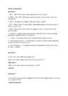
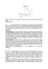
Ticket No1 1)The characteristic is called output characteristic or volt-ampere charateristic of a Rectifier Diode. 2)Rectifier Diode. 3) A is called Anode and C is called Cathode. An Anode has positive potential and therefore collects electrons in the device. Cathode has negative potential and therefore emits electrons to anode. The symbol looks like an arrow that ponts from the anode to the cathode, and reminds that conventional current flows easily from the p side(anode) to the n side(cathode). BIASING. Forward biasing. If the current in a diode is too large, excessive heat will destroy the device. Even approaching the burnout current value without reaching it can shorten its life. Therefore manufacturer's data sheet specifies the maximum forward current, that diode can withstand. This average current IF is the rate a diode can handle up to the forward direction when used as a rectifier. Another entry of interest in the da
oData transparency: In bit and byte oriented protocols, there is a problem if a control character (for ETX (End of Text) ·Same as ETB, only no more blocks will follow. ITB (End of > Differences with HDLC length of protocol field (1B or 2B) byte-oriented protocols) or the start-of-frame flag (for bit-oriented protocols) appears in the actual data. Intermediate Transmission Block) ·Same as ETB, except that the receiving statio Differs from HDLC because of multiaccess MAC that provides · Maximum payload length (default: 1500) This was not likely to happen in ASCII text, but is very likely with binary data. This is known as a data will not acknowledge after the error checking. EOT (End of Transmission) framing/error detection: · Type of CRC (2B or 4B) transparency problem an can be rectified with byte stuffing (for byte-orien
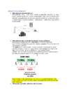
Eksami küsimused: 1. Mida tähendab mitmekiireline levi Mitmekiireline levi – info levib mööda peegeldusi, otselevi on väga harva. Kohale jõuab mitu lainet samaaegselt. Halb, sest lained liituvad (võivad tasakaalustada ennast ning signaal kustub ära, nõrgeneb). Kuna inimene liigub, muutub sagedus – lainepikkus – tuleb kogu aeg kanalit järgi kruttida. 2. Mida tähendab alla- ja üleslüli ning dupleks kaugus mobiilsides Pertaining to computer networks, a downlink is a connection from data communications equipment towards data terminal equipment. This is also known as a downstream connection. The uplink port is used to connect a device or smaller local network to a larger network, or connect to the next "higher" device in the topology. For example, the edge switch connects "up" to the distribution layer managed switch. Lühidalt - The communication going from a satellite to ground is called downlink, and when it is


Kõik kommentaarid