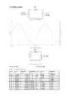
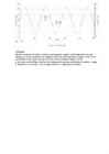
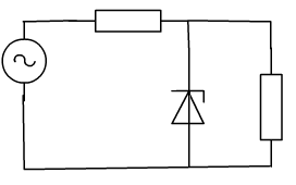
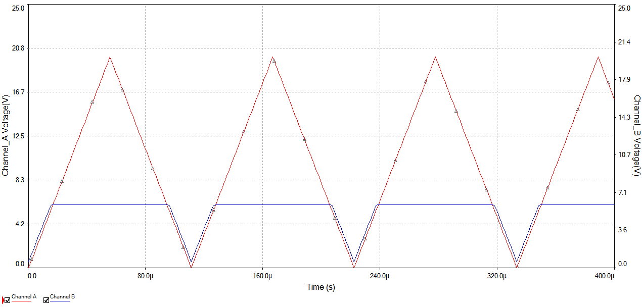
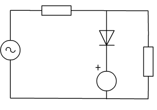
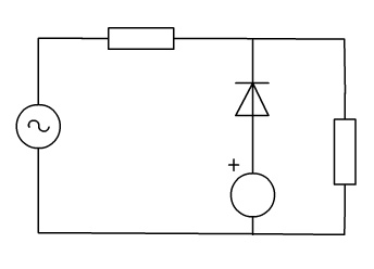
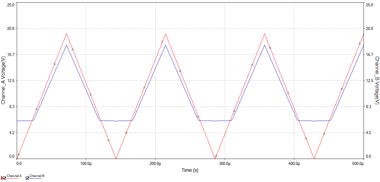
Ticket No1 1)The characteristic is called output characteristic or volt-ampere charateristic of a Rectifier Diode. 2)Rectifier Diode. 3) A is called Anode and C is called Cathode. An Anode has positive potential and therefore collects electrons in the device. Cathode has negative potential and therefore emits electrons to anode. The symbol looks like an arrow that ponts from the anode to the cathode, and reminds that conventional current flows easily from the p side(anode) to the n side(cathode). BIASING. Forward biasing. If the current in a diode is too large, excessive heat will destroy the device.
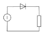
Analog Interfacing to Embedded Microprocessors Real World Design Analog Interfacing to Embedded Microprocessors Real World Design Stuart Ball Boston Oxford Auckland Johannesburg Melbourne New Delhi Newnes is an imprint of Butterworth–Heinemann. Copyright © 2001 by Butterworth–Heinemann A member of the Reed Elsevier group All rights reserved. No part of this publication may be reproduced, stored in a retrieval system, or transmitted in any form or by any means, electronic, mechanical, photocopying, recording, or otherwise, without the prior written permission of the publisher. Recognizing the importance of preserving what has been written, Butterworth–Heinemann prints its books on acid-free paper whenever possible. Library of Congress Cataloging-in-Publication Data Ball, Stuart R., 1956– Analog interfacing to embedded microprocessors : real world design / Stuart Ball. p. cm. ISBN 0-7506-7339-7 (pbk. : alk. paper) 1. Embedded computer
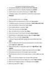
· The induction machines are associated with the names of Dolivo-Dobrovolsky Tesla · One of the first eletrical motors has been built by Jacobi · Electromagnetic efficiency is measured in tesla · Time constants are measured by ms s hours · Who is the author of the first electrical motor Henry · Which rectifier cannot be built without a transformer 3-phase midpoint · Call the benefits of 3-phase rectifiers upon the 1-phase ones output voltage · Which rectifier has more diodes 3-phase bridge · In the case of high-pass filter before the load, what can you tell about the current higher · What is the difference between the construction and operation of a rectifier and an inverter input wave output wave · What are the advantages of a single-phase bridge inverter high efficiency high reliability · What kind of control provides the highest output power of the inverter block · What load inductance provides the interruptible output current zero
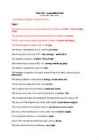
Test VIII - cumulative test by Piigli, Mets, Parker, Kauler "Top delusion" question / answers are red. Test I The induction machines are associated with the names of Dolivo - Dobrovolsky, Tesla. The synchronous machines are associated with the name of Ferraris. The DC machines are associated with the names of Jacobi and Henry. The electromagnetic torque is born in air gap. The torque is proportional to the current in dc motor. Which equations are correct? P = sW; oomega = tuletis fii'st The angular frequency is 2*pi()*n / 60 ja 2*pi()f The motor torque is equal to TL + J * oomega tuletis aja järgi The inductor supplies the motor with flux. The leading companies in the world market of electrical drive engineering are: Mitsubishi. The energy balance is described by energy conservation law. The armature supplies the motor with current. The cheapest and the most reliable is induction motor. The torque productio
Cat. No. W317-E1-11 SYSMAC CPM1A Programmable Controllers OPERATION MANUAL CPM1A Programmable Controllers Operation Manual Revised October 2007 iv Notice: OMRON products are manufactured for use according to proper procedures by a qualified operator and only for the purposes described in this manual. The following conventions are used to indicate and classify precautions in this manual. Always heed the information provided with them. Failure to heed precautions can result in injury to people or dam- age to property. ! DANGER Indicates an imminently hazardous situation which, if not avoided, will result in death or serious injury. Additionally, there may be severe property damage. ! WARNING Indicates a potentially hazardous situation which, if not avoided, could result in death or serious inju
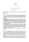
Tallinn University Natural and exact sciences Molecular Biochemistry and Ecology Maria Gnidenko Capillary electrophoresis Essay Supervisor: Kert Martma Tallinn 2015 Table of contents Acronyms and symbols used Introduction History and development Physical basis and principle of separation Elektrophoresis Electroosmotic flow Separation process Electrodispersion Various methods of separation Capillary zone?
[vaata | 1. Füüsikaliste suuruste mõisted, definitsioonid ja ühikud muuda] Voolu töö ja võimsus. Joule-Lenzi seadus. Potentsiaal ja pinge. Elektriväli, suund ja tugevus. Voolu tugevus ja tihedus. Takistus, selle sõltuvus juhi mõõtmetest. Eritakistus. Laeng ja mahtuvus. Induktiivsus. Vooliuallika elektromotoorjõud, lühisvool ja sisetakistus. Voolu töö ja võimsus. Voolu töö on võrdeline voolutugevusega I, pingega U juhi otstel ja ajaga t. [ J ] Võimsus on ajaühikus tehtud töö. [ W ] A p= t Joule-Lenzi seadus. Joule-Lenzi seadus : elektrivoolu toimel juhis eralduv soojushulk Q on võrdeline voolutugevuse I ruuduga, juhi takistusega R ja voolu kestusega t ning kus voolu töö on võrdelin
People who need enlightenment in that regard will find a wealth of explanatory literature collected on the shelves of any public library; no real purpose would be served by lingering over the matter here. Neither will I attempt to instruct you in the elementary mathematics and physics required to grasp much of what follows, as again the public library is an entirely adequate source of information. What will be provided is a kind of “state of the art” report about high- speed, high-output two-stroke engines for laymen-who in most cases do not have access to the literature (SAE papers, etc.) available to engineers and thus must rely upon hunches (often wrong) and folklore (almost invariably wrong) for guidance. Many have learned, to their sorrow, that it is distinctly possible to lavish enormous amounts of time and money on the two-stroke engine without realizing a return appropriate to the investment


Kõik kommentaarid