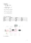
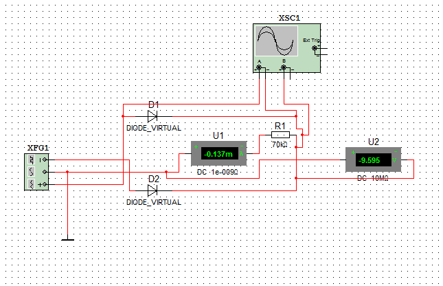
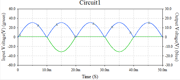
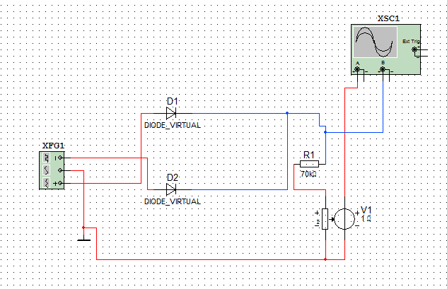
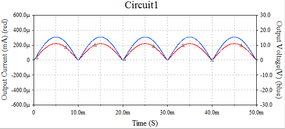
Tallinn University of Technology Department of Electricl Power Engineering and Mechatronics Report on Exercises 1 on Power Electronics Single-Phase Half-Wave Rectifiers Tallinn 2017 Given parameters: Output voltage, Ud = 10 V Input frequency, fin = 50 Hz Load resistance, Rload = 70 kOhm Calculations: u1 10 I d= = =0.143 mA R L 70000 πUd 3.14∗10 US= = =22.2 V √2 √2 PIV =π∗Ud=3.14∗10=31.42V U max =√ 2∗U s=√ 2∗22.2=31.4 V Table 1. Value comparison table.
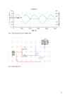
Tallinn University of Technology Department of Electricl Power Engineering and Mechatronics Report on Exercises 3 on Power Electronics Three-Phase Rectifiers Tallinn 2017 Given parameters: Output voltage, Ud = 10 V Input frequency, fin = 50 Hz Load resistance, Rload = 70 kOhm Calculations: M3 rectifier: u1 10 I d= = =0.143 mA R L 70000 2π Ud 2 π∗10 U ¿max = = =12.09 V 3 √3 3 √3 U ¿ max 12.09 U ¿rms = = =8.55V √2 √2
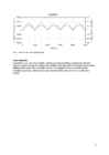
Tallinn University of Technology Department of Electricl Power Engineering and Mechatronics Report on Exercises 4 on Power Electronics AC Voltage Regulators Tallinn 2017 Given parameters: Output voltage, Ud = 20 V Input frequency, fin = 50 Hz Load resistance, Rload = 70 kOhm Calculations: U ¿ =2∗U out =2∗20=40V U max U rms = =17.09 V √2 Period = pulse width + delay => 10 ms = 5 ms + 5 ms Table 1. Control curve data. Delay time, Pulse with, Alpha, firing Switch SCR ms ms angle Uout, V Iout, mA Uout, V Iout, mA 0 10 0 28.14 0.52 21.28 0.25 2
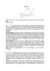
Ticket No1 1)The characteristic is called output characteristic or volt-ampere charateristic of a Rectifier Diode. 2)Rectifier Diode. 3) A is called Anode and C is called Cathode. An Anode has positive potential and therefore collects electrons in the device. Cathode has negative potential and therefore emits electrons to anode. The symbol looks like an arrow that ponts from the anode to the cathode, and reminds that conventional current flows easily from the p side(anode) to the n side(cathode). BIASING. Forward biasing
It turned out that this particu- lar drive had a thermal compensation feature that required the on-drive CPU to “go away” for a few tens of milliseconds every so often. The application required continuous access to the drive. Be sure the peripheral hardware is compatible with your application and does not introduce problems. Shared Interfaces What is the impact of shared interfaces? For example, if you are continuously buffering data from two different image cameras on two disk drives, a single IDE interface may not be fast enough. You may need separate IDE interfaces for the two drives so they can operate independently, or you may need to go to a higher-performance interface. Similarly, will 10-baseT Ethernet handle all your data, or will you need 100-baseT? Look at all the data on all the inter- faces and make sure the bandwidth you need is there. Task Priorities The IBM PC architecture has been used for all number of applications. It is
Tallinn University of Technology Department of Electrical Engineering Filters Report on Exercise 5 in AAR3320 Electronics and Semiconductor Engineering Student: Student Code: Study Group: Instructor: Prof. Valery Vodovozov Tallinn 1. RC filter R Vnoise 1000Ω 15 Vrms 11kHz 0Deg RL V C1 11kΩ 7.23µF 11.23 Vrms IC=0V 11 Hz 0Deg Figure 1. Circuit diagram of the low-pass RC filter Calculations f = 11 Hz Rc = 11 kΩ UL = 10 V R1 = 1
Tallinn University Natural and exact sciences Molecular Biochemistry and Ecology Maria Gnidenko Capillary electrophoresis Essay Supervisor: Kert Martma Tallinn 2015 Table of contents Acronyms and symbols used Introduction History and development Physical basis and principle of separation Elektrophoresis Electroosmotic flow Separation process Electrodispersion Various methods of separation Capillary zone?
Cat. No. W317-E1-11 SYSMAC CPM1A Programmable Controllers OPERATION MANUAL CPM1A Programmable Controllers Operation Manual Revised October 2007 iv Notice: OMRON products are manufactured for use according to proper procedures by a qualified operator and only for the purposes described in this manual. The following conventions are used to indicate and classify precautions in this manual. Always heed the information provided with them. Failure to heed precautions can result in injury to people or dam- age to property. ! DANGER Indicates an imminently hazardous situation which, if not avoided, will result in death or serious injury. Additionally, there may be severe property damage. ! WARNING Indicates a potentially hazardous situation which, if not avoided, could result in death or serious inju


Kõik kommentaarid