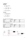
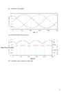
Tallinn University of Technology Department of Electricl Power Engineering and Mechatronics Report on Exercises 1 on Power Electronics Single-Phase Half-Wave Rectifiers Tallinn 2017 Given parameters: Output voltage, Ud = 10 V Input frequency, fin = 50 Hz Load resistance, Rload = 70 kOhm Calculations: u1 10 I d= = =0.143 mA R L 70000 πUd 3.14∗10 US= = =22.2 V √2 √2 PIV =π∗Ud=3.14∗10=31.42V U max =√ 2∗U s=√ 2∗22.2=31.4 V Table 1. Value comparison table.
Tallinn University of Technology Department of Electricl Power Engineering and Mechatronics Report on Exercises 2 on Power Electronics Single-Phase Full-Wave Rectifiers Tallinn 2017 Given parameters: Output voltage, Ud = 10 V Input frequency, fin = 50 Hz Load resistance, Rload = 70 kOhm Calculations: u1 10 I d= = =0.143 mA R L 70000 πUd 3.14∗10 US= = =11.1 V 2 √2 2 √2 U Smax =U S∗√ 2=11.1∗√ 2=15.7 V PIV =2∗U smax =2∗15.7=31.4 V I max=I d∗√ 2=0.143∗√ 2=0.2 V Table 1. Value comparison table.
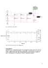
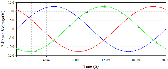
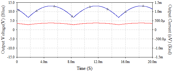
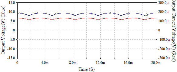
Tallinn University of Technology Department of Electricl Power Engineering and Mechatronics Report on Exercises 4 on Power Electronics AC Voltage Regulators Tallinn 2017 Given parameters: Output voltage, Ud = 20 V Input frequency, fin = 50 Hz Load resistance, Rload = 70 kOhm Calculations: U ¿ =2∗U out =2∗20=40V U max U rms = =17.09 V √2 Period = pulse width + delay => 10 ms = 5 ms + 5 ms Table 1. Control curve data. Delay time, Pulse with, Alpha, firing Switch SCR ms ms angle Uout, V Iout, mA Uout, V Iout, mA 0 10 0 28.14 0.52 21.28 0.25 2
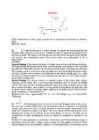
Ticket No1 1)The characteristic is called output characteristic or volt-ampere charateristic of a Rectifier Diode. 2)Rectifier Diode. 3) A is called Anode and C is called Cathode. An Anode has positive potential and therefore collects electrons in the device. Cathode has negative potential and therefore emits electrons to anode. The symbol looks like an arrow that ponts from the anode to the cathode, and reminds that conventional current flows easily from the p side(anode) to the n side(cathode). BIASING. Forward biasing
Analog Interfacing to Embedded Microprocessors Real World Design Analog Interfacing to Embedded Microprocessors Real World Design Stuart Ball Boston Oxford Auckland Johannesburg Melbourne New Delhi Newnes is an imprint of Butterworth–Heinemann. Copyright © 2001 by Butterworth–Heinemann A member of the Reed Elsevier group All rights reserved. No part of this publication may be reproduced, stored in a retrieval system, or transmitted in any form or by any means, electronic, mechanical, photocopying, recording, or otherwise, without the prior written permission of the publisher. Recognizing the importance of preserving what has been written, Butterworth–Heinemann prints its books on acid-free paper whenever possible. Library of Congress Cataloging-in-Publication Data Ball, Stuart R., 1956– Analog interfacing to embedded microprocessors : real world design / Stuart Ball. p. cm. ISBN 0-7506-7339-7 (pbk. : alk. paper) 1. Embedded computer
Cat. No. W317-E1-11 SYSMAC CPM1A Programmable Controllers OPERATION MANUAL CPM1A Programmable Controllers Operation Manual Revised October 2007 iv Notice: OMRON products are manufactured for use according to proper procedures by a qualified operator and only for the purposes described in this manual. The following conventions are used to indicate and classify precautions in this manual. Always heed the information provided with them. Failure to heed precautions can result in injury to people or dam- age to property. ! DANGER Indicates an imminently hazardous situation which, if not avoided, will result in death or serious injury. Additionally, there may be severe property damage. ! WARNING Indicates a potentially hazardous situation which, if not avoided, could result in death or serious inju
Surface TextureContour Measuring Instruments Explanation of Surface CharacteristicsStandards Definition of Surface texture and Stylus instrument Profile by Stylus and phase correct filter ISO4287: '97 and ISO3274: '96 Total profile Primary profile P Measure perpendicular to lay X axis Z
3 Pre-activation ............................................................................................. 334 18.4 Warm up ..................................................................................................... 334 18.5 Central section ........................................................................................... 339 18.6 Progression phase...................................................................................... 339 18.7 Recovery phase.......................................................................................... 339 18.8 Prevention phase........................................................................................ 341 19. STRETCHING .....................................................


Kõik kommentaarid