Vajad kellegagi rääkida?
Küsi julgelt abi LasteAbi
Logi sisse

Electronics and semiconductor engineering exercise 1 (0)

5 VÄGA HEA
Punktid
Tallinn University  of  Technology
Department of Electrical  Engineering
ELECTRONICS AND 
SEMICONDUCTOR  ENGINEERING
Exercises
Linear circuits
Student: xxxxxxxx
Codexxxxxx
Group: xxxxxx
TALLINN
xxxx
1.1  RL- Circuit
L1
Uout=4V
V1
100mH 
232.5 Vrms 
R1
5kHz 
54Ω
-89° 
Figure  .1: RL-circuit
Figure 1.: Input and  load   voltage
Figure 1.:  Frequency  response
Figure 1.: Frequency response
         Comparative  data table 
Calculated   Experiment
Quantity
value
al value
Uamp,V
328
327,98
I, A
0,074
0,074
Uout,V
4
3,99
UL,V
232,5
231,9
ϕ
-89
-89
∆, s
-0,000049
-0,000050
A, dB
-35,2
-35,3
Calculations
f=5 kHz  
L= 100 mH
R= 54 Ω 
Uout= 4 V
 
  
Conclusion
There  are only slight  differences , which may be caused by experimental and calculation errors 
but otherwise calculated and experimented results are very  similar .
1.2  RC-Circuit
C1
Uout=4V
1uF 
V1
R1
4.64 Vrms 
54Ω
5kHz 
30° 

Figure 2.1: RC-circuit
Figure 2.2: Input and load voltage
Figure 2.3: Frequency response
Figure 2.4: Frequency response
        Comparative data table 2
Calculated  Experiment
Quantity
value
al value
Uamp,V
6,56
6,55
I, A
0,074
0,074
Uout,V
4
3,99
UC,V
2,36
2,36
ϕ
30
30,52
∆, s
-0,000017
-0,000018
A, dB
-1,1
-1,3
Calculations
C= 1 µF
R= 54 Ω 
Uout= 4 V
f= 5 kHz
Us= I ∙ Z


Conclusion
Experimental and calculated results are very similar. The slight difference may be caused by 
errors in calculations or experimental circuit.
1.3 RLC-Circuit
L1
C1
Uout=4V
100mH 
1uF 
V1
R1
230.16 Vrms 
54Ω
5kHz 
-89° 

Figure 3.1: RLC-circuit
Figure 3.2: Input and load voltage
Figure 3.3: Frequency response
Figure 3.4: Frequency response
        Comparative data table 3
Calculated  Experiment
Quantity
value
al value
Uamp,V
325,5
325,47
I, A
0,074
0,074
Uout,V
4
3,99
UL,V
232,5
232,48
UC,V
2,36
2,35
ϕ
-89
-89
∆, s
-0,000049
-0,000050
A, dB
-35,08
-35,02
Calculations
C= 1 µF
L=100 mH
R= 54 Ω 
Uout= 4 V
f= 5 kHz
Us= I ∙ Z


Conclusion
Experimental and calculated results are very similar. The slight difference may be caused by 
errors in calculations or experimental circuit.
1.4
 Series  resonant  circuit
L1
C1
1.013mH
V1
IC=0A
1uF 
Uout=4V
3.996 Vrms 
R1
54Ω
5kHz 
0° 
Figure 4.1: Series resonant circuit
Figure 4.2: Input and load voltages(Us=Uout because XC=XL) 
Figure 4.3: Frequency response
Figure 4.4: Frequency response
   Comparative data table 4
Calculated  Experiment
Quantity
value
al value
Uamp,V
5,65
5,65
I, A
0,074
0,74
Uout,V
4
3,99
UL,V
2,355
2,356
UC,V
2,355
2,355
ϕ
0
0,009
∆, s
0
0
A, dB
0
0
Calculations
C= 1 µF
R= 54 Ω 
Uout= 4 V
f= 5 kHz
Us= I ∙ Z


Conclusion
Experimental and calculated results are very similar. The slight difference may be caused by 
errors in calculations or experimental circuit. UL=UC because of the voltage resonance.
1.5 Parallel  resonant circuit
Uout=4V
V1
L1
3.996 Vrms 
1.013mH
C1
R1
1uF 
54Ω
5kHz 
IC=0A
0° 
Figure 5.1: Parallel resonant circuit
Figure 5.2: Input and load voltage (US=Uout)
Figure 5.3: Frequency response
Figure 5.4: Frequency response
   Comparative data table 5
Calculated  Experiment
Quantity
value
al value
Uamp,V
5,65
5,65
I, A
0,074
0,74
Uout,V
4
3,99
UL,V
3,99
3,99
UC,V
3,99
3,99
IL
0,126
0,126
IC
0,126
0,126
ϕ
0
0
∆, s
0
0
A, dB
0
0
Calculations
C= 1 µF
R= 54 Ω 
Uout= 4 V
f= 5 kHz
Us= I ∙ Z
 
 bacause of the prallel circuit
 
 
Conclusion
Experimental and calculated results are very similar. The slight difference may be caused by 
errors in calculations or experimental circuit. IL=IC because of the  current  resonance.
Vasakule Paremale
Electronics and semiconductor engineering exercise 1 #1 Electronics and semiconductor engineering exercise 1 #2 Electronics and semiconductor engineering exercise 1 #3 Electronics and semiconductor engineering exercise 1 #4 Electronics and semiconductor engineering exercise 1 #5 Electronics and semiconductor engineering exercise 1 #6 Electronics and semiconductor engineering exercise 1 #7 Electronics and semiconductor engineering exercise 1 #8 Electronics and semiconductor engineering exercise 1 #9
Punktid 50 punkti Autor soovib selle materjali allalaadimise eest saada 50 punkti.
Leheküljed ~ 9 lehte Lehekülgede arv dokumendis
Aeg2013-03-26 Kuupäev, millal dokument üles laeti
Allalaadimisi 11 laadimist Kokku alla laetud
Kommentaarid 0 arvamust Teiste kasutajate poolt lisatud kommentaarid
Autor Visual Õppematerjali autor

Sarnased õppematerjalid

Filters report 5 Electronics and Semiconductor Engineering
10
docx

Filters report 5 Electronics and Semiconductor Engineering

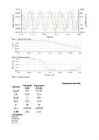
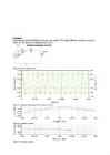
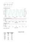
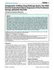
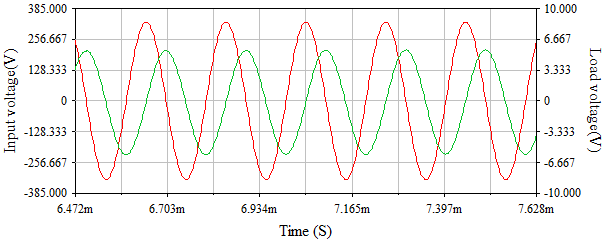
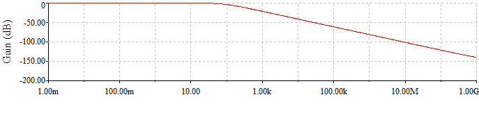
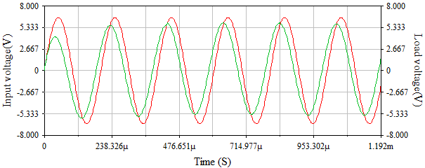
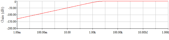
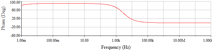
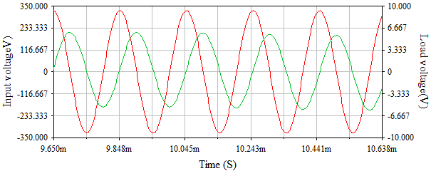
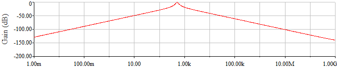
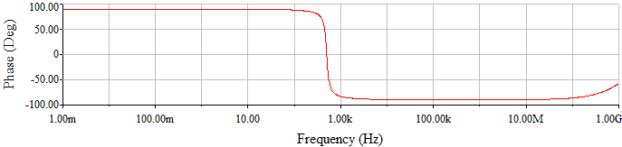
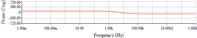
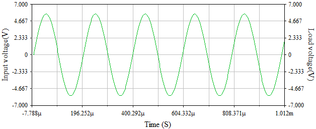
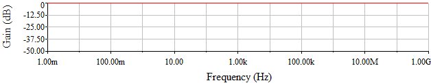
Tallinn University of Technology Department of Electrical Engineering Filters Report on Exercise 5 in AAR3320 Electronics and Semiconductor Engineering Student: Student Code: Study Group: Instructor: Prof. Valery Vodovozov Tallinn 1. RC filter R Vnoise 1000Ω 15 Vrms 11kHz

Elektrimaterjald
Book Analog Interfacing to Embedded Microprocessors
568
pdf

Book Analog Interfacing to Embedded Microprocessors

I hope it proves useful. ix Introduction Modern electronic systems are increasingly digital: digital microprocessors, digital logic, digital interfaces. Digital logic is easier to design and understand, and it is much more flexible than the equivalent analog circuitry would be. As an example, imagine trying to implement any kind of sophisticated micro- processor with analog parts. Digital electronics lets the PC on your desk execute different programs at different times, perform complex calculations, and communicate via the World Wide Web. While the electronic world is nearly all digital, the real world is not. The temperature in your office is not just hot or cold, but varies over a wide range. You can use a thermometer to determine what the temperature is, but how do you convert the temperature to a digital value for use in a microprocessor- controlled thermostat

Mehhatroonika
Piletid vastustega
13
docx

Piletid vastustega

junction. The incoming light produces free electrons and holes. The stronger the light, the greater the number of minority carriers and the larger the reverse current. Optocoupler: LED on the input side and photodiode on the output side. Light from the led hits the photodiode and this sets up a reverse current in the output circuit. 8) How many valence electrons a germanium atom has? 1 2 4 8 How is it called the n-type semiconductor? donor recipient acceptor dipol Ticket No3 ´ 1,2)Collector characteristic(output characteristics) and input characteristic of Bipolar Junction Transistor(BJT) 3)A junction transistor has three doped regions. The bottom is the emitter, middle is base and top is collector.A transistor has two junctions on opposite sides of a thin slaf of semiconductor

Elektroonika jõupooljuht tehnika
Report on Exercises 2 - Diodes
11
pdf

Report on Exercises 2 - Diodes

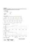
Tallinn University of Technology Department of Electrical Drives and Power Electronics Report on Exercises 2 Diodes Student ******* Code ****96 Group AAVB41 Tallinn 2012 2.1. Diode rectifier VD f = 9 kHz U=6V U = 19.7 V

Elektroonika jõupooljuht tehnika
Study of heat transfer coefficient in helical coil
52
docx

Study of heat transfer coefficient in helical coil

INSTITUTO POLITECNICO DO PORTO INSTITUTO SUPERIOR DE ENGENHARIA DO PORTO CHEMICAL ENGINEERING DEPARTMENT PORTUGAL Marvin Üürike Tallinn University of Technology Faculty of Chemical and Materials Technology Department of Chemical Engineering Estonia ERASMUS PROJECT STUDY OF THE HEAT TRANSFER COEFFICIENT IN A HELICAL COIL Supervisor: Albina Ribeiro Porto 2015 2 Abstract The following work investigates overall heat transfer coefficient of a helical coil and how it changes in different situations. The variables investigated were flow rate inside a submerged helical coil and agitation of the bath.

Kategoriseerimata
Thesis Kivimaa August 2022
140
pdf

Thesis Kivimaa August 2022

Thesis “How is it possible to calculate IT security effectiveness?” Kristjan Kivimaa August 2022 1 Abstract In IT Security world, there is lack of available, reliable systems for measuring security levels/posture. They lack the range of quantitative measurements and easy and fast deployment, and potentially affects companies of all sizes. Readily available security standards provide qualitative security levels, but not quantitative results – that would be easily comparable. This deficiency makes it hard for companies to evaluate their security posture accurately. Absence of security metrics makes it complicated for customers to select the appropriate measures for particular security level needed. The research question for this research project is – “How is it possible to calculate IT security effectiveness?”. The aim of this research is to use this reference m

Infotehnoloogia
CPM1A Programmable Controllers Operation Manual 1784470
402
pdf

CPM1A Programmable Controllers Operation Manual 1784470

Cat. No. W317-E1-11 SYSMAC CPM1A Programmable Controllers OPERATION MANUAL CPM1A Programmable Controllers Operation Manual Revised October 2007 iv Notice: OMRON products are manufactured for use according to proper procedures by a qualified operator and only for the purposes described in this manual. The following conventions are used to indicate and classify precautions in this manual. Always heed the information provided with them. Failure to heed precautions can result in injury to people or dam- age to property. ! DANGER Indicates an imminently hazardous situation which, if not avoided, will result in death or serious injury. Additionally, there may be severe property damage. ! WARNING Indicates a potentially hazardous situation which, if not avoided, could result in death or serious inju

Automatiseerimistehnika
Mageveekäsna Ephydatia fluviatilis populatsiooni geneetiline analüüs
12
pdf

Mageveekäsna Ephydatia fluviatilis populatsiooni geneetiline analüüs

Intragenomic Profiling Using Multicopy Genes: The rDNA Internal Transcribed Spacer Sequences of the Freshwater Sponge Ephydatia fluviatilis Liisi Karlep, To~nu Reintamm, Merike Kelve* Department of Gene Technology, Tallinn University of Technology, Tallinn, Estonia Abstract Multicopy genes, like ribosomal RNA genes (rDNA), are widely used to describe and distinguish individuals. Despite concerted evolution that homogenizes a large number of rDNA gene copies, the presence of different gene variants within a genome has been reported. Characterization of an organism by defining every single variant of tens to thousands of rDNA repeat units present in a eukaryotic genome would be quite unreasonable. Here we provide an alternative approach for the characterization of a set of internal transcribed spacer sequences found within every rDNA repeat unit by implementing direct sequencing methodology. The prominent allelic variants and their relative amounts c

Eesti loomad


Meedia

Kommentaarid (0)

Kommentaarid sellele materjalile puuduvad. Ole esimene ja kommenteeri


Sellel veebilehel kasutatakse küpsiseid. Kasutamist jätkates nõustute küpsiste ja veebilehe üldtingimustega Nõustun