Test VIII - cumulative test by Piigli, Mets, Parker, Kauler "Top delusion" question / answers are red. Test I The induction machines are associated with the names of Dolivo - Dobrovolsky, Tesla. The synchronous machines are associated with the name of Ferraris. The DC machines are associated with the names of Jacobi and Henry. The electromagnetic torque is born in air gap. The torque is proportional to the current in dc motor. Which equations are correct? P = sW; oomega = tuletis fii'st The angular frequency is 2*pi()*n / 60 ja 2*pi()f The motor torque is equal to TL + J * oomega tuletis aja järgi The inductor supplies the motor with flux. The leading companies in the world market of electrical drive engineering are: Mitsubishi. The energy balance is described by energy conservation law. The armature supplies the motor with current. The cheapest and the most reliable is induction motor. The torque productio
Electrical drives and power electronics TESTS · The synchronous machines are associated with the names of Ferraris · Name the scientists who first studied electrical phenomena Coulomb · The DC machines are associated with the names of Jacobi Henry · The leading companies in the world market of electrical drive engineering are Mitsubishi · · The electromagnetic torque is born in air gap · What kind of drives the majority of drive systems present low accuracy · The induction machines are associated with the names of Dolivo-Dobrovolsky Tesla · One of the first eletrical motors has been built by Jacobi · Electromagnetic efficiency is measured in tesla · Time constants are measured by ms s hours · Who is the author of the first electrical motor Henry · Which rectifier cannot be built without a transformer 3-phase midpoint · Call the benefits of 3-phase rectifiers upon the 1-phase ones output voltage · Which rectifier has more diodes 3-phase bridge · In th
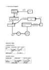
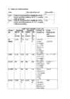
Tallinn University of Technology Department of Electrical Engineering Report on laboratory work 1 on General Course of Electrical Drive SENSORLESS DRIVE POWER FLEX (ALLEN BRADLEY) Jüri Lina 666BMW Group M16 Variant 2 Tallinn 2014 1. Functional Diagram 2. Tables of observations Task Operation/Record Observation 1 Reverse the motor speed. How long Time to reverse was 16 does the motor reverse? seconds 2 2: Set the screen display an Output Minimal: 2.8V Voltage of the inverter. Turning the Maximal: 166V potentiometer, find accessible minimal and maximal voltages. Stop the drive. 3 3 Turn the keypad potentiometer half- Reverse ti
Analog Interfacing to Embedded Microprocessors Real World Design Analog Interfacing to Embedded Microprocessors Real World Design Stuart Ball Boston Oxford Auckland Johannesburg Melbourne New Delhi Newnes is an imprint of Butterworth–Heinemann. Copyright © 2001 by Butterworth–Heinemann A member of the Reed Elsevier group All rights reserved. No part of this publication may be reproduced, stored in a retrieval system, or transmitted in any form or by any means, electronic, mechanical, photocopying, recording, or otherwise, without the prior written permission of the publisher. Recognizing the importance of preserving what has been written, Butterworth–Heinemann prints its books on acid-free paper whenever possible. Library of Congress Cataloging-in-Publication Data Ball, Stuart R., 1956– Analog interfacing to embedded microprocessors : real world design / Stuart Ball. p. cm. ISBN 0-7506-7339-7 (pbk. : alk. paper) 1. Embedded computer
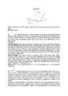
Ticket No1 1)The characteristic is called output characteristic or volt-ampere charateristic of a Rectifier Diode. 2)Rectifier Diode. 3) A is called Anode and C is called Cathode. An Anode has positive potential and therefore collects electrons in the device. Cathode has negative potential and therefore emits electrons to anode. The symbol looks like an arrow that ponts from the anode to the cathode, and reminds that conventional current flows easily from the p side(anode) to the n side(cathode). BIASING. Forward biasing. If the current in a diode is too large, excessive heat will destroy the device. Even approaching the burnout current value without reaching it can shorten its life. Therefore manufacturer's data sheet specifies the maximum forward current, that diode can withstand. This average current IF is the rate a diode can handle up to the forward direction when used as a rectifier. Another entry of interest in the da
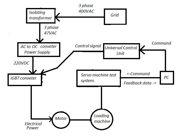
Tallinn University of Technology Department of Electrical Engineering Report on laboratory work 3 on General Course of Electrical Drive SERVO DRIVE (FESTO) Jüri Lina 666BMW Group M16 Variant 2 Tallinn 2014 1. Functional Diagram Component list: PC with Wmmemoc software SEC-AC-305 controller MTR-AC-55 servo motor with encoder External 24VDC power supply unit Test stand with slide and limit switches 4. Tables of observations Task Operation/Record Observation 1 Measure the slide position at Limit Slide moved to the right, switch 1 Limit 1 reached at 1,46 2 Turn potentiometer slowly counter- Slide sta
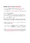
Question 1 (in wiki and in terminologies) 1. SNR is a calculated value that represents the ratio of root- mean-square (rms ) signal to rms noise. 2. SINAD stands for Signal-to-noise and distortion ratio. It is a measure of the quality of a signal from a communications device, often defined as: where is the average power of the signal, noise and distortion components. SINAD is usually expressed in dB. For examples to calculate the ratio of 1 kW (one kilowatt, or 1000 watts) to 1 W in decibels, use the formula 3. ENOB is the effective number-of-bits related to SINAD and the quality of a digitized signal. The 6.02 term in the divisor converts decibels (a log10) to bits (a log2) The 1.76 term comes from quantization error in an ideal ADC 4. THD - Total harmonic distortion is the ratio of the root-mean-square (rms) value of the fundamental signal to the mean value
different uses - even though that inevitably means that it will do no single thing particularly well. In these areas will we find the latitude for “improving” an engine, and one should always be mindful that the real task is simply to tailor a mass-use product to a very specific application- and that in the tailoring process one inevitably will incur all the various expenses the engine's designer has avoided. Hours of labor may be required to finish rough-cast ports; dollars will be spent correcting other things that are the creatures of manufacturing economies; power added at maximum revs will be power subtracted at lower crankshaft speeds, while the increased speeds required to obtain large improvements in power output will be paid for in terms of reliability. 1 Two Stroke TUNER’S HANDBOOK Another mistake commonly made, sometimes even by those who have enjoyed


Kõik kommentaarid