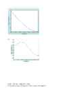
Microcontroller homework for week 05 1. Treshold, sensitivity, (full) range, linearity, accuracy, precision, stability, hysteresis, noise 2. VO = RH/(RT+RH) = 0.381356 V 3. A) 100 B) 212,464 4. A) B) R1 = 16,67 k C) D) E) RF = 10k, RL = 28k2, RH = 107k F) Before scaling: 2.35 steps/°C. After scaling: 3.42 steps/°C 5. Some things were assumed, as they were not given. 30 = 1,13V 40 = 0,976V So 35 should be between 40 and 30. Assuming about 1,053 V. Same for 5 degrees... Assuming about 1,725 V. 35 degrees digital 1,053/10*1024 = 107,8272 5 degrees digital 1,725/10*1024 = 176,64 177 108 = 69 ADC counts, 30 degrees SPAN 69/30 = 2,3 ADC steps per degree We need the tempertatur
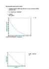
output voltage for a relative humidity of 70 % at 30 °C if R T = 50 kΩ and VDD= 2.5 V. R70 30 c =R H =9,2 kV RH 9,2 k V O= ∙ V DD= ∙ 2,5 = 0,388 V (R T + R H ) ( 50 k +9,2 k ) Hint: Check specification for Humidity Sensor of SYH-2R.pdf at http://www.rhopointcomponents.com/images/SYH-2R.pdf 2 Week 04 Homework Question 3 Given the following bridge circuit for a strain gauge, determine the value of the strain gauge resistance {RS}. Let: VIN = 5V R3 = 200 Ω R2 = 50 Ω R1 = 100 Ω a) Under no strain (VOUT = 0 V) R2 ∙ R3 RS= =100 Ω R1 b) When VOUT = 0,5 V {under strain}. 100 200 0,1= − 150 200+ RS 200 200 0,56= =¿> RS= −200=¿> RS=157 Ω 200+ RS 0,56 RS ≈157 Ω
Solution: 1. Thershold. 2. Sensitivity. 3. Full Range. 4. Linearity. 5. Accuracy. 6. Precision. 7. Stability. 8. Hysteresis. 9. Noise. Question 2 Given the circuit below (using a SYH-2R humidity sensor) determine the output voltage for a relative humidity of 70 % at 30 °C if RT = 50 kΩ and VDD= 2.5 V. Solution: Check specification for Humidity Sensor of SYH-2R.pdf at: http://www.rhopointcomponents.com/images/SYH-2R.pdf 2 Week 04 Homework - Solutions Check Thermistor - Wikipedia.pdf at http://en.wikipedia.org/wiki/Thermistor Calculate the Humidity Sensor resistance at 30°C T = 273.15°C +30°C = 303.15°C T0 = 273.15°C +25°C = 298.15°C R60% 30°C =25.5858 kΩ - Matlab code: 33*exp(4600*(1/303.15-1/298.15)) = 25.5858 Calculate the Humidity Sensor resistance at relative humidity 70% See the above graphic for the standard resistance: Exercises - Solutions 3
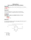
Midterm Exam Microcontrollers and Practical Robotics Question 1 Convert the decimal number 43.982 to (a) binary and (b) hex. Show all your calculations. a.) 101011.111110 b.) 2B.FB6 Question 2 Perform the calculation of 58 – 42 by first converting each decimal value to binary and then using the twos complement method. Show all your calculations 5810=001110102 4210=001010102 Converse to twos complement 4210=001010102=110101012+1=110101102 Then 58+(42) 001110102 +110101102 = 000100002 =1610 Question 3 Given the following bridge circuit for a strain gauge, determine the value of the strain gauge resistance {RS}. Let: VIN = 5V R3 = 100 Ω R2 = 50 Ω R1 = 100 Ω 2 Midterm Exam - Solutions a) Under no strain (VOUT = 0 V) b) When VOUT = 0,5 V {under strain}. Solution: a) Under no strain: R1 R3 R1R4 R2 R3 VOUT IN
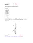
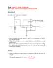
Read Chapter_6_Analog_Outputs.pdf and Chapter_8_EMI_ElectroMagnetic_Interference.pdf Question 1 Given the below open sensor detection: a. Derive equations for both outputs VO and Vsense as a function of VR, R1, Rth, RH, RL and RF. b. What value will appear on each output if the thermistor fails (becomes an open circuit)? c. How can the above schem be modified to implement temperature reading with open sensor detection using only one ADC and one digital input pin of the microcontroller? Solution: a. Derive equations for both outputs as a function of VR, R1, Rth, RH, RL and RF. Rth Writing the equation for V1 : V1 VSense VR th R R1 V0 V2 VR V2 V2 Writing the equation for V2 : RF RH RL
Dynamic Range 1 Calibration 2 Bandwidth 5 Processor Throughput 6 Avoiding Excess Speed 7 Other System Considerations 8 Sample Rate and Aliasing 11 2 Digital-to-Analog Converters 13 Analog-to-Digital Converters 15 Types of ADCs 17 Sample and Hold 26 Real Parts 29 Microprocessor Interfacing 30 Serial Interfaces 36 Multichannel ADCs 41 Internal Microcontroller ADCs 41 Codecs 42 Interrupt Rate 43 Dual-Function Pins on Microcontrollers 43 Design Checklist 45 v 3 Sensors 47 Temperature Sensors 47 Optical Sensors 59 CCDs 72 Magnetic Sensors 82 Motion/Acceleration Sensors 86 Strain Gauge 90 4 Time-Based Measurements 93
c) Vin = 0.836 V V¿ 0. 836 ∗RS ∗17 k 2,09 V 2,09 ∗1 ∗1 = =1000kHz RL 100 k 0,4∗170∗1 f OUT = = = =10 0 0000 R t∗ct 6,8 k∗0,01 μ 68 μ Question 5 Question 6 One of the reasons for using time/frequency based measurements in microcontroller systems is to be able eliminate ground loops. Explain the unwanted ground loop that may occur in an electrical scheme with the help of a figure. Ground loop refers to an unwanted current in an electrical system. This is caused by a conductor that is connecting two points that are supposed to have same potential, but actually have different potentials, often ground. Noise and interference in electronics are mostly caused by falsely installed or created ground loops. Ground loop occurs when
Homework-04 Solution (100 marks) Read Chapter_4_Time_Based_Measurements.pdf Question 1 (10 marks) When converting an analogue value to a frequency, consider the following diagram describing the system. The frequency changes from 20 MHz to 18 MHz and the system samples at an interval of 2ms. How many counts does the microprocessor detect at, a) 20 MHz? b) 18 MHz? What is the difference in terms of number of counts detected by the microprocessor? Solution: 1 1 a) Converse 20 MHz to time length: T 0.00005ms f 20,000,000 2ms Number of counts in 2ms: N 40,000 0.00005ms 1 1 b) Converse 18 MHz to time length: T 0.000055556ms f 20,000,000


Kõik kommentaarid