Task 1: 1. Lubrication system 2. Moving parts 3. Heat and wear 4. Cooling 5. Lubricates 6. Collects 7. Particles 8. Oil filter 9. Leak out 10. Amount 11. Checking 12. Dipstick 13. Friction 14. Increase 15. Become damaged 16. Changing 17. Thin 18. Impurities 19. Efficiently 20. Assembled Task 2: 1. Oil pressure switch, oil pump, relief valve, oil strainer, relief valve for oil cooler, oil filter, oil cooler, main gallery, oil pan, oil level gauge 2. Static seals and dynamic seals 3. Paper filter, or it may contain oil 4. Wire gauze, nylon mesh, cotton, felt, pads, paper or cellulose sheets Task 3: 1
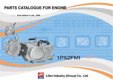
--9 -- E-6 Right Crankcase Cover S/N Part No. Description Quantity Remark 1 11310/1P50FMG Cover comp., crankcase, RH 1 2 11319/1P50FMG Gasket, crankcase cover, RH 1 3 11331/1P50FMG Lid, small, RH 1 4 34931/1P50FMG Clip, ignition coil wire 1 5 15611/1P50FMG Dipstick, plasitc 1 6 22810/1P50FMG Lever comp., clutch 1 7 22821/1P50FMG Spring, clutch lever 1 8 22825/1P50FMG Pin, clutch lever 1 9 22826/1P50FMG Detent, clutch 1 10 22827/1P50FMG Plate, clutch lever pressure 1 11 22851/1P50FMG Screw, clutch adjusting 1
--9 -- E-6 Right Crankcase Cover S/N Part No. Description Quantity Remark 1 11310/1P50FMG Cover comp., crankcase, RH 1 2 11319/1P50FMG Gasket, crankcase cover, RH 1 3 11331/1P50FMG Lid, small, RH 1 4 34931/1P50FMG Clip, ignition coil wire 1 5 15611/1P50FMG Dipstick, plasitc 1 6 22810/1P50FMG Lever comp., clutch 1 7 22821/1P50FMG Spring, clutch lever 1 8 22825/1P50FMG Pin, clutch lever 1 9 22826/1P50FMG Detent, clutch 1 10 22827/1P50FMG Plate, clutch lever pressure 1 11 22851/1P50FMG Screw, clutch adjusting 1
Excessive pressure in the starting air system is released by the safety valve (9), incorporated in the line. FUEL OIL SYSTEM The fuel oil is normally stored in the bottom tanks of the ship. The bottom tanks are provided with filling and discharge pipes. As a rule, bunker oils are delivered at a temperature of 50-60ºC in order to make pumping easier. The bottom tanks are provided with sounding equipment for checking the amount of oil in the tanks. Sounding can always be carried out by using a dipstick. If the engine uses heavy fuel oil, the bottom tanks must have heating coils, because the viscosity of the oil is often so high that the transfer pump is unable to suck the oil up from the tanks. The transfer pump which can, for example, be a gear pump or a screw pump, sucks fuel oil through a coarse filter and feeds it to one of two settling tanks. The fuel oil is heated in the settling tanks up to 80 - 90º C to allow some water and sludge to settle out by gravity and be drained off.
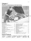
Renew the brake fluid (Section 39) Maintenance - Component location 1·5 Engine and under bonnet component location on 1986 1.4 litre models (air cleaner removed for clarity) 1 Fuse and relay box 2 Windscreen wiper motor 3 Engine oil dipstick 4 Carburettor 5 Fuel pump 6 Battery negative terminal 7 Brake master cylinder reservoir 8 Distributor 9 Ignition coil 10 Washer reservoir 11 Thermostat housing 12 Oil filler cap 13 Vehicle identification plate 14 Engine tuning decal 15 Cooling system expansion tank 16 Suspension strut top mounting 1