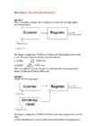
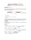
a) Why do we require a low-pass filter when using this mixer circuit? Mixer needs more parts b) Name another disadvantage of such a mixer circuit. The mixer approach multiplies the frequency shift you want to measure, but also any other frequency shift. This includes drift caused by component heating, noise, etc. Question 4 Consider the following circuit and input waveform. Question 3 Draw an equivalent output waveform. Question 3 Question 5 Consider the following LM231 voltage to frequency converter (see LM331.pdf). Assume Rs = 17 kΩ. (Hint: Find the formula to calculate the output frequency fOUT and the values of Rs, RL, Rt, and Ct in LM331.pdf). Determine the output frequency (fOUT). a) Vin = 0.0836 V V¿ 0.0836 ∗RS ∗17 k 2,09 V 2,09 ∗1 ∗1 = 100kHz RL 100 k 0,04∗170∗1
shifts (origiral, sum, etc.). This includes noises and heating. - If the input frequency comes down and the difference frequency will increases up and may be filtered aways by the low pass filter. - The design of the mixer is complecated. - The circuit may produce more ElectroMagnetic Interference (EMI) Question 4 (10 marks) Consider the following circuit and input waveform. Draw an equivalent output waveform. Solution: Question 5 (20 marks) Consider the following LM231 voltage to frequency converter (see LM331.pdf). Assume Rs = 17 kΩ. Determine the output frequency (fOUT). a) Vin = 0.0836 V b) Vin = 0.418 V c) Vin = 0.836 V Solution: Determine the output frequency (fOUT). From the chart, Rs = 17 kΩ, RL = 100 kΩ, Rt = 6.8 kΩ, Ct = 0.01 µF. a) For Vin = 0.0836 V, fOUT= 100 Hz b) For Vin = 0.418 V, fOUT= 500 Hz c) For Vin = 0.836 V, fOUT= 1kHz Question 6 (10 marks) One of the reasons for using time/frequency based measurements in
components are extremely important. Likewise, capacitor C1 and resistor R1 determine the output frequency. It is typical to use precision resistors and Teflon, polystyrene, or polypropylene capacitors in V-F circuits. On startup, the capacitor has to be charged from 0v to the input voltage. The one-shot “on” time may be too short to insure that this happens. Typi- cally, the switch is left in the charge mode until V- reaches the input voltage. The LM231 from National Semiconductor is a typical V-F converter. This part uses an internal voltage reference to set the charging current; a resistor from an external pin to ground determines the current. The LM231 is capable of operation from 1 Hz to 100 kHz. So far, we have looked at asynchronous V-F converters. A synchronous V-F converter works the same way, except that an external clock determines the “on” time that charges the capacitor. This makes the V-F characteristics inde-