if S1[bitindex] S2[bitindex] Y = false Exit loop end end end 9. A) V and C (the operation produced an overflow and the operation produced a carry) b) N (The result of the operation is negative) 10. 10 17 memory chip 11. a) Suitable clock frequency 0 400 kHz b) The loop lasts 1 µs (1/16*4*4). The delay should be for half (5 µs) the clock period. 12. Connect the following pins: MAX232:T1IN PIC:Tx MAX232:R1OUT PIC:Rx MAX232:R1IN RS232:TxD MAX232:T1OUT RS232:RxD
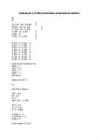
5) 3A9 + 24D 9+D=6 A+4=F 3+2=5 Answer is 5F6 6) Y = X shl 3 7) evaluate true: A and B (not A)and(not B) 8) Y = true for i from 1 to 20 for j from 1 to 8, excluding 3 bitindex = j + (i-1)*8 if S1[bitindex] S2[bitindex] Y = false Exit loop end end end 9) a) V and C b) N 10) 11) a) 0-400 kHz b) The delay needs to last for half the clock period, because it is in the middle of high and low edges. Using a 100kHz EEPROM clock. The loop last 1 microsecond. 12) MAX232:T1IN <=> PIC:Tx MAX232:R1OUT <=> PIC:Rx MAX232:R1IN <=> RS232:TxD MAX232:T1OUT <=> RS232:RxD
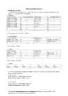
12. You are designing an embedded system and need to communicate with a computer motherboard using an RS-232 interface. You decided to use a MAX232 driver to convert between the voltage levels used by the PIC and those used by the RS-232 port (find a MAX232 datasheet on the internet). You are using a PIC18F45K20. Indicate, on the following diagram, how you would connect the PIC, the MAX232 and the RS-232 port. You have to connect following pins : MAX232:T1IN ↔ PIC:Tx MAX232:R1OUT ↔ PIC:Rx MAX232:R1IN ↔ RS232:TxD MAX232:T1OUT ↔ RS232:RxD