Kuidas muudab mudelprojekteerimine teraskonstruktsioonide valmistamist ja ehitamist
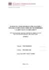
member utilizing a centerpunch mark to locate and install a reflective tape target (Figure
20) on the surface of the column. Total Station surveying instruments were programmed
with this information.
Figure 19. Total Station Surveying Target in the Field (left). Figure 20. Modeled Targets
on a Wide Flange Column (Curtis Mayes, personal communication, May 10, 2010).
The project routinely had very large skewed gusset plates that were shop fitup and shop
welded. Changes to the design were submitted to the fabrication team accompanied by
3D wireframe electronic files that accurately positioned the added or changed members in
3D space.
With the help of 3D visualization tools, Arup was able to coordinate the frame, ductwork
and piping, minimizing coordination-related requests for information. Every beam
penetration was factory-cut and its location known during the design phase (Figure 21).