Ticket No1 1)The characteristic is called output characteristic or volt-ampere charateristic of a Rectifier Diode. 2)Rectifier Diode. 3) A is called Anode and C is called Cathode. An Anode has positive potential and therefore collects electrons in the device. Cathode has negative potential and therefore emits electrons to anode. The symbol looks like an arrow that ponts from the anode to the cathode, and reminds that conventional current flows easily from the p side(anode) to the n side(cathode). BIASING. Forward biasing. If the current in a diode is too large, excessive heat will destroy the device. Even approaching the burnout current value without reaching it can shorten its life. Therefore manufacturer's data sheet specifies the maximum forward current, that diode can withstand. This average current IF is the rate a diode can handle up to the forward direction when used as a rectifier. Another entry of interest in the da
Dynamic Range 1 Calibration 2 Bandwidth 5 Processor Throughput 6 Avoiding Excess Speed 7 Other System Considerations 8 Sample Rate and Aliasing 11 2 Digital-to-Analog Converters 13 Analog-to-Digital Converters 15 Types of ADCs 17 Sample and Hold 26 Real Parts 29 Microprocessor Interfacing 30 Serial Interfaces 36 Multichannel ADCs 41 Internal Microcontroller ADCs 41 Codecs 42 Interrupt Rate 43 Dual-Function Pins on Microcontrollers 43 Design Checklist 45 v 3 Sensors 47 Temperature Sensors 47 Optical Sensors 59 CCDs 72 Magnetic Sensors 82 Motion/Acceleration Sensors 86 Strain Gauge 90 4 Time-Based Measurements 93
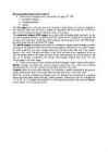
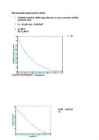
Tallinn University of Technology Department of Electrical Drives and Power Electronics Report on Exercises 2 Diodes Student ******* Code ****96 Group AAVB41 Tallinn 2012 2.1. Diode rectifier VD f = 9 kHz U=6V U = 19.7 V R = 96 k Figure 1. Circuit diagram Figure 2. Timing diagram VD + R = 96 k -
Microcontroller homework for week 12 1. Three different stepper motors (illustrations on page 162-163): · permanent-magnet, · variablereluctance, · hybrid. The VR stepper has a soft iron rotor with teethand a wound stator. As current is applied to two opposing stator coils, the rotor is pulled into alignment with these twocoils. As the next pair of coils is energized, the rotor advances to the next position. The permanent magnet (PM) stepper has a rotor with alternating north and south. As the coils are energized, the rotor is pulled around. This figure shows a single coil to illustrate the concept, but a realstepper would have stator windings surrounding the rotor. The PM stepper has more torque than an equivalent VR stepper. The hybrid stepper essentially adds teeth to a permanent magnet motor,resulting in better coupling of the magnetic field into the rotor and moreprecise movement. In a hybrid stepper, the rotor is split into two parts, anupper and lo
Microcontroller homework for week 05 1. Treshold, sensitivity, (full) range, linearity, accuracy, precision, stability, hysteresis, noise 2. VO = RH/(RT+RH) = 0.381356 V 3. A) 100 B) 212,464 4. A) B) R1 = 16,67 k C) D) E) RF = 10k, RL = 28k2, RH = 107k F) Before scaling: 2.35 steps/°C. After scaling: 3.42 steps/°C 5. Some things were assumed, as they were not given. 30 = 1,13V 40 = 0,976V So 35 should be between 40 and 30. Assuming about 1,053 V. Same for 5 degrees... Assuming about 1,725 V. 35 degrees digital 1,053/10*1024 = 107,8272 5 degrees digital 1,725/10*1024 = 176,64 177 108 = 69 ADC counts, 30 degrees SPAN 69/30 = 2,3 ADC steps per degree We need the tempertatur
Microcontroller homework for week 04 1. SNR - Ratio of RMS signal to RMS SINAD - Ratio of the RMS signal amplitude to the mean value of the root-sum-square (RSS) ENOB - The effective number-of-bits and relates to SINAD THD - Ratio of the rms value of the fundamental signal to the mean value of the RSS of its harmonics. SFDR - Ratio of the RMS value of the signal to the RMS value of the worst spurious signal. Channels related to the inputs of the ADC can either be multiplexed or individually selected. Linearity relates to how a ADC follows a linear function. All ADCs are to a certain extend non-linearity. Temperature is measurement, which in optimal state for ADC-s, lets them function correctly. Power dissipation refers to the amount power dissipated when the ADC is operating. 2. The output code is 001111012 and the voltage of the LSB is 0,0195V 3. The output code is 101011101101100 4. The
Question 1 Define the following ADC terms: 1. SNR – (Signal to Noise Ratio) SNR is a calculated value that represents the ratio of RMS signal to RMS noise. 2. SINAD - (signal-to-noise-and-distortion ratio) Ratio of the RMS signal amplitude to the mean value of the root-sum-square (RSS) 3. ENOB – (effective number of bits) The effective number-of-bits and relates to SINAD 4. THD - (total harmonic distortion) Ratio of the rms value of the fundamental signal to the mean value of the RSS of its harmonics. 5. SFDR - (spurious free dynamic range) Ratio of the RMS value of the signal to the RMS value of the worst spurious signal. 6. Channels - related to the inputs of the ADC can either be multiplexed or individually selected. 7. Linearity - relates to how a ADC follows a linear function. All ADCs are to a certain extend nonlinearity. 8. Operating temperature - measurement, which i
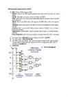
11 00 0000 0000 - 11 11 1111 1111 (0xC00-0xFFF) Three inputs NAND chip and scheme Scheme used four of the PROM chips and four three-input NAND gates (CS = chip select pins) Scheme to coonect 12 input pins MP address to four PROM 10 address pins == MEMR (Merory Read) 11. You are designing a multi-user interface that stores user preference data on external memory. You decided to use a PIC18F45K20 microcontroller and 24C02C EEPROM memory. Your microcontroller needs to generate a block wave that will act as a clock signal to synchronize data transfer to and from the memory. a) Choose a suitable clock frequency, based on the capabilities of the EEPROM module and the PIC. b) Assume the clock frequency of the PIC is 16 MHz and one instruction cycle lasts 4 clock periods. Further assume that one loop of your algorithm requires 4 instruction cycles. Determine the total delay time for completing a command cycle sent to


Kõik kommentaarid