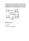
c) Vin = 0.836 V V¿ 0. 836 ∗RS ∗17 k 2,09 V 2,09 ∗1 ∗1 = =1000kHz RL 100 k 0,4∗170∗1 f OUT = = = =10 0 0000 R t∗ct 6,8 k∗0,01 μ 68 μ Question 5 Question 6 One of the reasons for using time/frequency based measurements in microcontroller systems is to be able eliminate ground loops. Explain the unwanted ground loop that may occur in an electrical scheme with the help of a figure. Ground loop refers to an unwanted current in an electrical system. This is caused by a conductor that is connecting two points that are supposed to have same potential, but actually have different potentials, often ground. Noise and interference in electronics are mostly caused by falsely installed or created ground loops. Ground loop occurs when
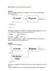
Homework-04 Solution (100 marks) Read Chapter_4_Time_Based_Measurements.pdf Question 1 (10 marks) When converting an analogue value to a frequency, consider the following diagram describing the system. The frequency changes from 20 MHz to 18 MHz and the system samples at an interval of 2ms. How many counts does the microprocessor detect at, a) 20 MHz? b) 18 MHz? What is the difference in terms of number of counts detected by the microprocessor? Solution: 1 1 a) Converse 20 MHz to time length: T 0.00005ms f 20,000,000 2ms Number of counts in 2ms: N 40,000 0.00005ms 1 1 b) Converse 18 MHz to time length: T 0.000055556ms f 20,000,000
Dynamic Range 1 Calibration 2 Bandwidth 5 Processor Throughput 6 Avoiding Excess Speed 7 Other System Considerations 8 Sample Rate and Aliasing 11 2 Digital-to-Analog Converters 13 Analog-to-Digital Converters 15 Types of ADCs 17 Sample and Hold 26 Real Parts 29 Microprocessor Interfacing 30 Serial Interfaces 36 Multichannel ADCs 41 Internal Microcontroller ADCs 41 Codecs 42 Interrupt Rate 43 Dual-Function Pins on Microcontrollers 43 Design Checklist 45 v 3 Sensors 47 Temperature Sensors 47 Optical Sensors 59 CCDs 72 Magnetic Sensors 82 Motion/Acceleration Sensors 86 Strain Gauge 90 4 Time-Based Measurements 93
Cat. No. W317-E1-11 SYSMAC CPM1A Programmable Controllers OPERATION MANUAL CPM1A Programmable Controllers Operation Manual Revised October 2007 iv Notice: OMRON products are manufactured for use according to proper procedures by a qualified operator and only for the purposes described in this manual. The following conventions are used to indicate and classify precautions in this manual. Always heed the information provided with them. Failure to heed precautions can result in injury to people or dam- age to property. ! DANGER Indicates an imminently hazardous situation which, if not avoided, will result in death or serious injury. Additionally, there may be severe property damage. ! WARNING Indicates a potentially hazardous situation which, if not avoided, could result in death or serious inju
oData transparency: In bit and byte oriented protocols, there is a problem if a control character (for ETX (End of Text) ·Same as ETB, only no more blocks will follow. ITB (End of > Differences with HDLC length of protocol field (1B or 2B) byte-oriented protocols) or the start-of-frame flag (for bit-oriented protocols) appears in the actual data. Intermediate Transmission Block) ·Same as ETB, except that the receiving statio Differs from HDLC because of multiaccess MAC that provides · Maximum payload length (default: 1500) This was not likely to happen in ASCII text, but is very likely with binary data. This is known as a data will not acknowledge after the error checking. EOT (End of Transmission) framing/error detection: · Type of CRC (2B or 4B) transparency problem an can be rectified with byte stuffing (for byte-orien
Ticket No1 1)The characteristic is called output characteristic or volt-ampere charateristic of a Rectifier Diode. 2)Rectifier Diode. 3) A is called Anode and C is called Cathode. An Anode has positive potential and therefore collects electrons in the device. Cathode has negative potential and therefore emits electrons to anode. The symbol looks like an arrow that ponts from the anode to the cathode, and reminds that conventional current flows easily from the p side(anode) to the n side(cathode). BIASING. Forward biasing. If the current in a diode is too large, excessive heat will destroy the device. Even approaching the burnout current value without reaching it can shorten its life. Therefore manufacturer's data sheet specifies the maximum forward current, that diode can withstand. This average current IF is the rate a diode can handle up to the forward direction when used as a rectifier. Another entry of interest in the da
Two-Stroke TUNER’S HANDBOOK By Gordon Jennings Illustrations by the author Copyright © 1973 by Gordon Jennings Compiled for reprint © 2007 by Ken i PREFACE Many years have passed since Gordon Jennings first published this manual. Its 2007 and although there have been huge technological changes the basics are still the basics. There is a huge interest in vintage snowmobiles and their “simple” two stroke power plants of yesteryear. There is a wealth of knowledge contained in this manual. Let’s journey back to 1973 and read the book that was the two stroke bible of that era. Decades have passed since I hung around with John and Jim. John and I worked for the same corporation and I found a 500 triple Kawasaki for him at a reasonable price. He converted it into a drag bike, modified the engine completely and added mikuni carbs and tuned pipes. John borrowed Jim’s cop
SISUKORD ENERGY STORY................................................................................................................4 USES OF ENERGY............................................................................................................. 4 2.1 Uses of energy in homes...............................................................................................5 2.2 Types of energy used in homes.................................................................................... 6 2.3 Energy use in different types of homes........................................................................ 6 2.4 Commercial Energy Use...............................................................................................9 2.5 Industrial and Manufacturing Energy Use..................................................................11 2.6 Transportation Energy Use.........................................................................................12 RENE


Kõik kommentaarid